

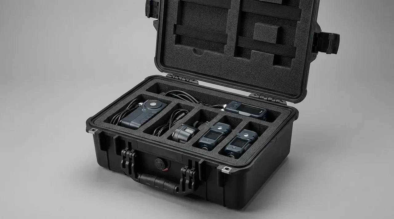
Quick answer: Case drop sequence runs one corner, three edges and six faces in ten drops, as a corner peaks 2.3 to 3.1 times higher than a face.
Table of contents
- Why the sequence starts at a corner
- Ordering one corner, three edges and six faces
- Matching drop height to case weight
- Judging the severest position
- Visual and functional checks after the drops
- FAQ
1. Why the sequence starts at a corner
Three edges meet at a corner, squeezing the impact into a projection near 12 cm², less than one eighth of the flat wall beside it. A 12 kg case from 760 mm peaks at 620–880 g on that corner and only 240–310 g on a face, a ratio of 2.3 to 3.1.
The two standards count differently. IEC 60068-2-31 works face by face, six faces twice each, twelve drops, order left to the tester. MIL-STD-810 Method 516.6 Procedure IV lists eight corners, twelve edges and six faces as twenty-six drops.
Our trial moulding used a 3.0 mm wall, 2.0 mm ribs and R10 bottom corners in ABS-PC. At the corner the walls meet without a rib, so section modulus is 40 percent lower than the panel, and R10 only pulls the stress factor down to 2.6. Those two numbers put drop one on a corner.
2. Ordering one corner, three edges and six faces
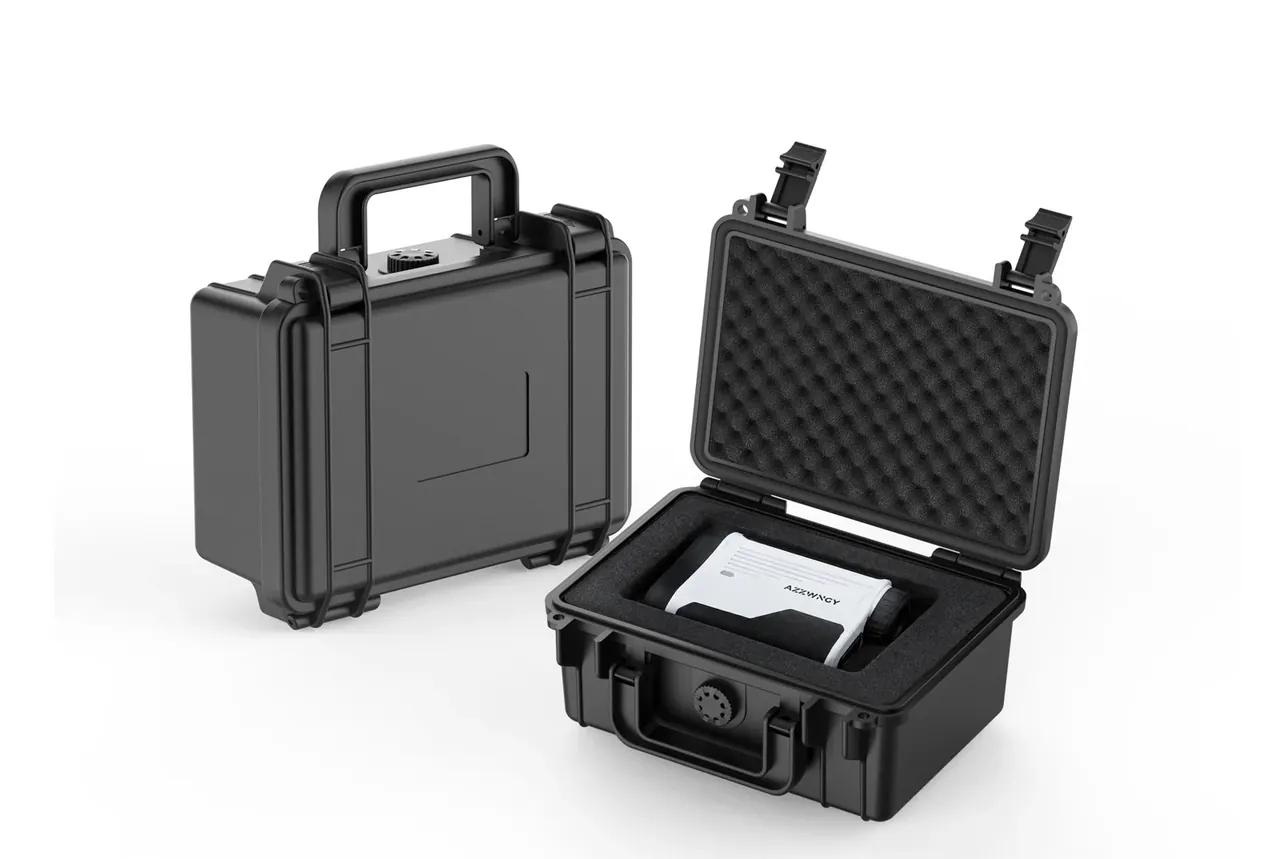
Fix the weakest corner, walk the three edges that meet it, then take the faces as bottom, top and four sides. Jumping around destroys comparability, since each impact rewrites the load path for the next.
| Drop | Attitude | Target | Watch for |
|---|---|---|---|
| 1 | Corner | Bottom corner opposite latches | Crush depth, R10 cracks |
| 2–4 | Edge | Three edges at that corner | Lipping, rib fracture |
| 5–6 | Face | Bottom, top | Bulge, latch pop |
| 7–10 | Face | Front, back, left, right | Denting, hinge shift |
The latch and handle side carries metal parts sharing load and runs 15–20 percent stiffer, so drop one goes to the bottom corner with no hardware. A contract reading "drop tested to IEC 60068-2-31" never learns whether that corner collapsed.
Three parallel samples beat one sample dropped thirty times. Sample one takes the corner opposite the latches, sample two the hinge-side corner, sample three the diagonal, and the set shows where thin spots cluster, which one sample cannot.
Rest 5 minutes between drops so elastic strain springs back; rapid drops carry strain forward and push crush depth 0.3–0.6 mm high. Release from an electromagnetic plate within 3 degrees, since hand release drifts 6 to 9 degrees and moves the strike onto an edge.
3. Matching drop height to case weight
Height is banded by net weight, not payload. Mass drives impact, so weigh case, foam and liner together.
| Net weight | Drop height | Drops | Impact speed |
|---|---|---|---|
| Up to 5 kg | 1200 mm | 10 | 4.85 m/s |
| 5.1–10 kg | 900 mm | 10 | 4.20 m/s |
| 10.1–20 kg | 760 mm | 10 | 3.86 m/s |
| 20.1–30 kg | 610 mm | 8 | 3.46 m/s |
| Above 30 kg | 460 mm | 6 | 3.00 m/s |
Write the tolerance as -0/+10 mm, measured from the lowest point of the case to the floor. Concrete of 100 mm or more and a 10 mm steel plate differ by 8–12 percent in peak acceleration, so name the surface or two labs never reconcile.
Cases above 20 kg take eight drops for practical reasons: lifting over 30 kg to 460 mm by hand is unsafe, and a hoist release drifts past 5 degrees.
More height is not stricter. The same 3.0 mm wall case from 1200 mm onto concrete crushes 3.2 mm and fails; at 900 mm it crushes 1.4 mm and looks acceptable, yet edge cracking grows likelier as energy turns into bending stress along the edge.
4. Judging the severest position
The severest position is not the biggest corner but the one with least restraint and highest stress concentration. The bottom corner opposite the latches reaches 2.6, the hinge side only 1.8, a 44 percent gap that fixes drop one.
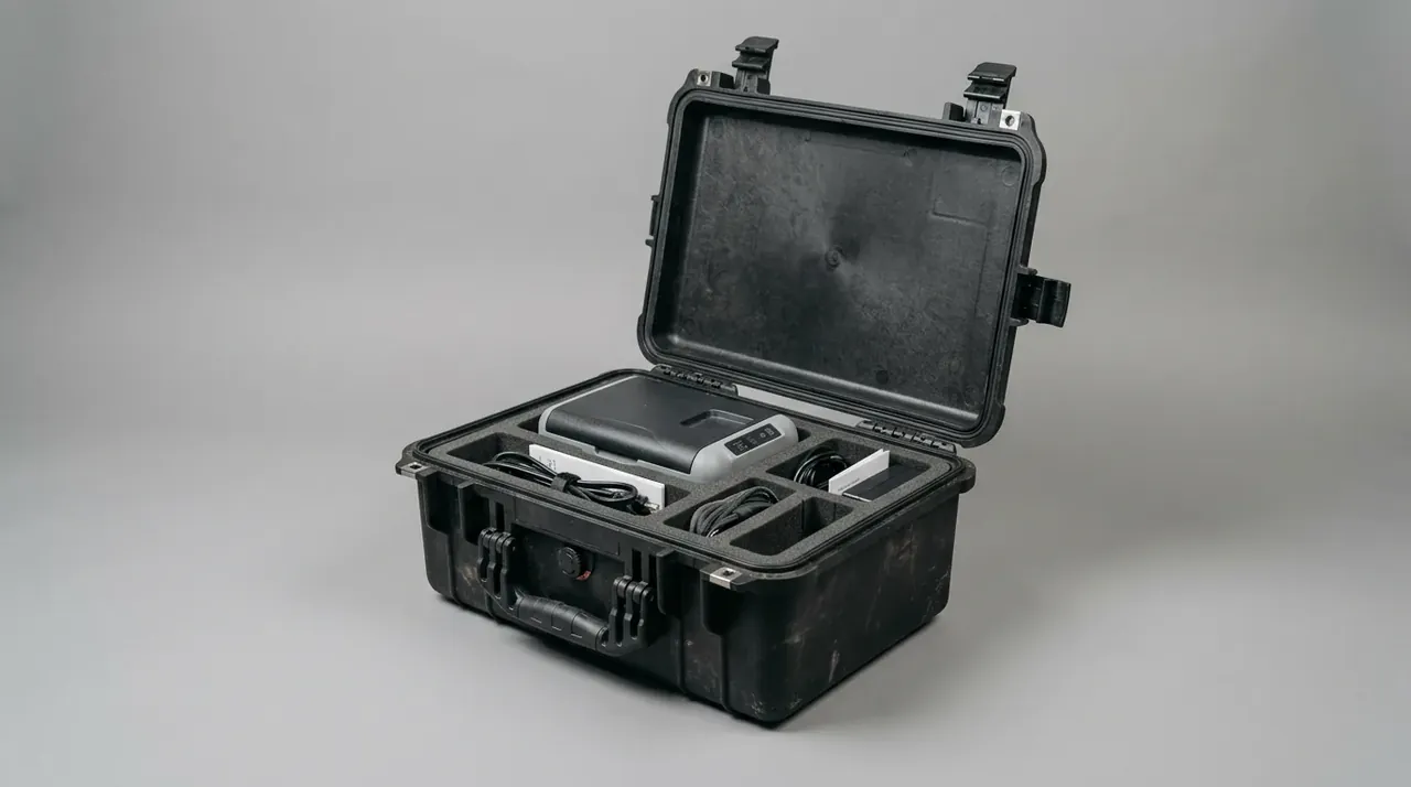
Judge in three layers: residual corner deformation, pressure decay, latch and hinge function. Failing any layer fails that attitude, and a missing layer cannot be tested later on its own.
Corner crush sits between 1.5 and 3.0 mm and is visible at arm's length. A longitudinal edge crack runs 3–8 mm and hides until the lid opens. Foam cavity tearing shows only after the insert comes out, which is why the lid opens after every group. A triaxial accelerometer inside the bottom corner, sampled at 10 kHz, reads the 620–880 g peak and its 1.2–1.8 ms pulse; that pulse marks the severest position while the other nine follow routine, cutting workload 30 percent.
5. Visual and functional checks after the drops
Visual inspection lands within 30 minutes of the last drop, with the functional check after it. Visual work needs immediate deformation, functional work the sprung-back state, and swapping them records 0.5 mm of recovery as permanent set.
| Check | Method | Limit | Action |
|---|---|---|---|
| Corner crush | Depth gauge, three points | 2.0 mm | Scrap |
| Edge crack | 20x magnifier | 3 mm, not through | Through-wall scraps |
| Panel bulge | Straight edge, 0.05 mm feeler | 1.5 mm | Record |
| Latch force | Force gauge, mean of three | 80 N | Replace |
| Hinge travel | Manual 0–180° | No binding | Adjust |
| Airtightness | 3 kPa for 30 s | 0.5 kPa decay | Check groove |
The handle mount is the most missed item: 0.5 mm micro-cracks at the boss hide at rest and surface in a 10-minute hang at twice rated load. Airtightness comes last, since every earlier check opens the lid and compresses the gasket again, blaming the drop for 0.2–0.4 kPa of decay.
Conclusion
A fixed order is worth more than a drop count, because it puts limited drops where the structure is weakest. A corner drop defines the structural limit, an edge drop exposes where cracks begin, and a face drop proves panel stiffness and latch retention; reorder them and the three sets contaminate each other.
Execution list: weigh case with foam and liner; mark the bottom corner opposite the latches as drop one; walk its three edges; take six faces as bottom, top, front, back, left, right; rest 5 minutes between drops; inspect within 30 minutes; hang the handle at twice rated load for 10 minutes; pressurise to 3 kPa for 30 s. A report missing one step is a claim, not a record.
This article discusses container-side specifications and design implications only, and does not cover any handling, loading or use of the contents.
Related Reading
- Drop height against case weight
- Running an ASTM D4169 distribution cycle
- Corner radius R10 versus R25 under load
- Latch force design and measurement
Related Products
- 8 Series — Gun Cases; Military Equipment Cases; Camera Equipment Cases; Drone Cases; Watch Cases; Knife Cases; First Aid Cases; Electronics Equipment Cases
- WL8-2812 PP Gun Case — model WL8-2812
- All protective cases and toolboxes: 7 series, 158 models