

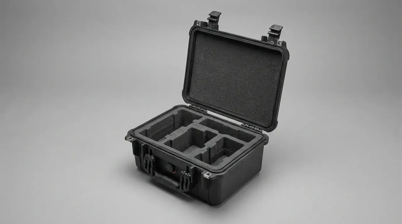
Quick answer: Case foam thickness follows pressure, not habit: divide weight by bearing area, add the drop factor, then match the 25% strain stroke.
Table of contents
- Case Foam Thickness Sets the Compression Stroke
- Read the Pressure, Then Pick a Thickness
- What 5, 10 and 15 mm Each Cover
- Stacking Three Layers Costs 30 mm
- FAQ
1. Case Foam Thickness Sets the Compression Stroke
Three numbers sit on the spec sheet: 5, 10 and 15 mm. What matters is the stroke the foam yields before it densifies, and thickness only caps that stroke.
At 30 kg/m³, EPE reaches roughly 50 kPa at 25% strain. Past that point the curve turns steep, and every extra millimetre of deflection costs a large jump in force. Design practice treats 25% as the working limit, so 5 mm gives 1.25 mm of stroke, 10 mm gives 2.5 mm, and 15 mm gives 3.75 mm.
Each extra millimetre of stroke absorbs more energy at the same peak force.
Thickness is also paid for out of the interior. A 15 mm pad on one side removes 15 mm of usable height, and pads on both sides remove 30 mm of width. A 15 mm liner is a poor default; it belongs on the weight class that needs the stroke.
Density moves the same line. At 45 kg/m³ the 25% stress rises to about 80 kPa, so the stroke stays put while the peak pressure a pad survives goes up. Check density before choosing a grade, or every row of the table shifts.
2. Read the Pressure, Then Pick a Thickness
Step one is static pressure: item weight divided by bearing area. A 2 kg device with a 120 × 80 mm footprint rests on 0.0096 m², giving about 2.0 kPa.
Step two applies the drop factor. In a 0.6 m free fall, peak pressure runs about 20 times the static value, so 2.0 kPa becomes 41 kPa. That stays under the 50 kPa line of 30 kg/m³ EPE at 25% strain, and the 10 mm grade holds.
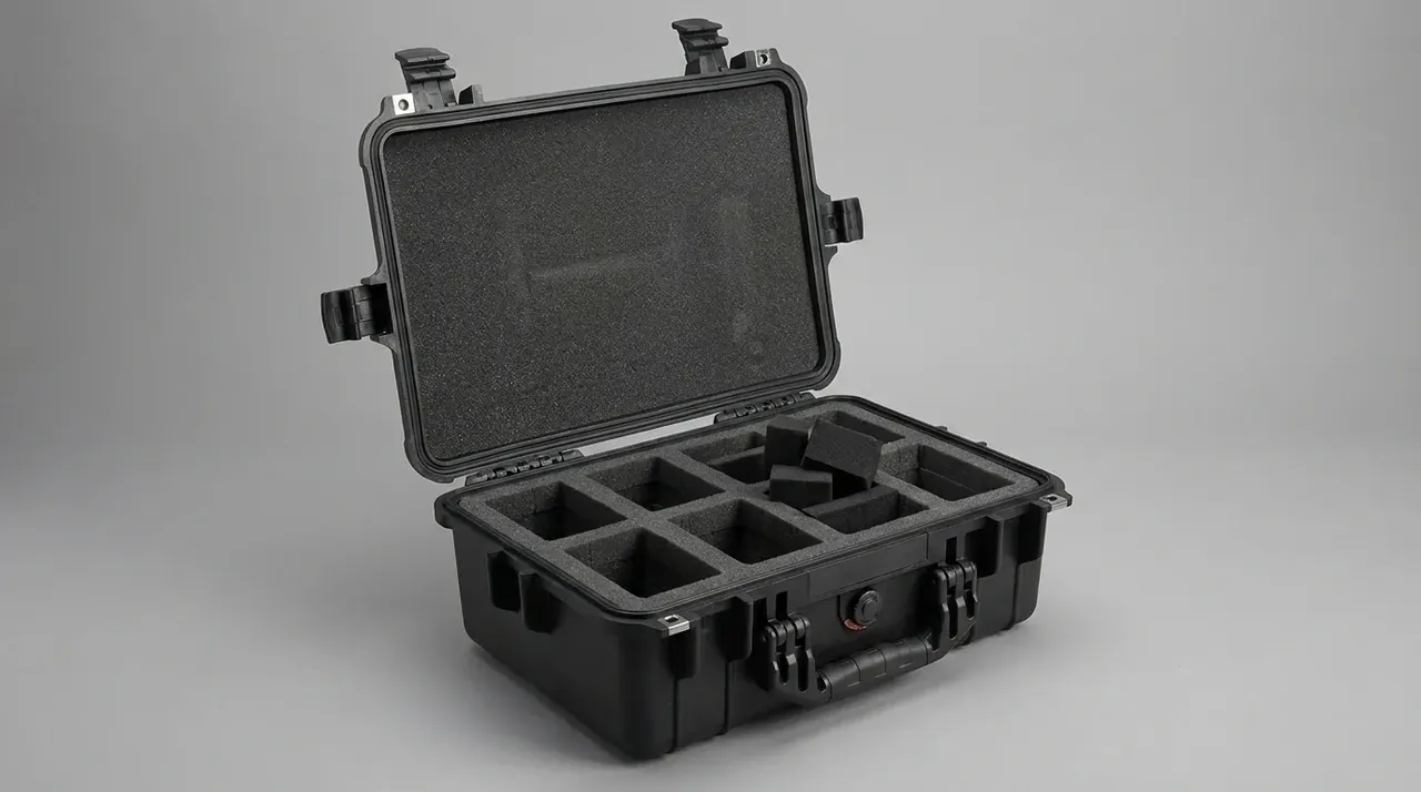
Step three is the lookup. Below 10 kPa peak, 5 mm is enough; 10 to 25 kPa calls for 10 mm; 25 to 50 kPa calls for 15 mm. Above 50 kPa the bearing area is the problem rather than the thickness, so widen the contact patch first.
Every row below comes from one drop tower; the reading is maximum foam deflection, not case displacement.
| Thickness | Stroke at 25% | Measured on the tower | Ceiling |
|---|---|---|---|
| 5 mm | 1.25 mm | 1.1 mm under 1 kg at 0.3 m | locating pad |
| 10 mm | 2.5 mm | 4.2 mm under 2 kg at 0.6 m | 1 to 3 kg |
| 15 mm | 3.75 mm | 42 J absorbed at 60% compression | 3 to 8 kg |
Measure bearing area at the real contact face. Four 10 mm feet carry the load on small patches, so the projected outline overstates the area three to five times and the chosen thickness comes out thin.
3. What 5, 10 and 15 mm Each Cover
The 5 mm grade is a locating pad. It suits items under 1 kg dropped from 0.3 m, such as face panels and thin sensors, and its job is to stop movement rather than absorb impact.
The 10 mm grade is the workhorse for handheld equipment. A 2 kg item dropped 0.6 m deflects 4.2 mm, which is 42% of the pad, already past the 25% design line. Any extra mass pushes it into the densified zone where load passes straight into the shell.
The 15 mm grade is rated at 42 J. For a 2 kg item that equals a 2.1 m free fall, and for an 8 kg item only 0.53 m. Heavier loads shorten the usable drop height on the same pad.
| Peak pressure, kPa | Thickness | Note |
|---|---|---|
| under 10 | 5 mm | locating only, 1.25 mm stroke |
| 10 to 25 | 10 mm | standard for handheld units |
| 25 to 50 | 15 mm | instruments, 42 J |
| above 50 | 15 mm doubled | widen the contact patch first |
When the peak lands between 25 and 50 kPa, 10 mm still fits, but deflection passes 50%, the foam densifies, recovery slows, and the lid feels stuck on opening.
Mixed loads follow the heaviest item, with the same grade filling the rest. Averaging is the usual mistake: a 4.5 kg unit inside a 2 kg average lands on a pad sized for half its mass.
4. Stacking Three Layers Costs 30 mm
Stacking 5, 10 and 15 mm in search of a pad that is both soft and firm is common. The layers add up to 30 mm, and the interior loses all 30 mm.
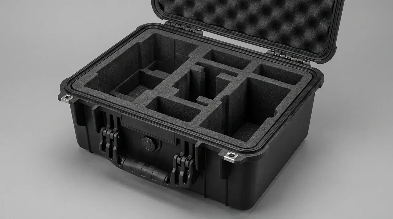
Stacking carries a second cost. Layers do not bond, so each interface slips 2 to 3 mm under side load, three layers accumulate 6 to 9 mm of drift, and the item sits crooked.
Bonded layers behave as their softest member. Adhesive adds 0.5 mm, and a 5 mm skin on the outside drags the whole block down to the 5 mm grade.
| Equipment type | Unit weight | Thickness | Reason |
|---|---|---|---|
| handheld terminal | 0.8 to 2 kg | 10 mm | 4.2 mm at 0.6 m |
| optical instrument | 3 to 5 kg | 15 mm | needs 42 J |
| panel or thin part | under 1 kg | 5 mm | locating only |
| metal tool | 5 to 8 kg | 15 mm plus plate | guard the corners |
The lid pad counts toward the total as well. A 10 mm lid pad over a 15 mm base pad clamps at 25 mm, yet impact still runs through the base, and the lid only holds the item down.
Three measurements come before any stack. Weigh the item, measure the footprint, and find the sharpest point. Weight sets the grade, footprint sets the pressure, and the sharp point decides whether a guard plate is needed. Once those numbers exist, the case foam thickness is settled.
Conclusion
Case foam thickness is settled by pressure first, stroke second, and millimetres last. A 2 kg handheld device dropped 0.6 m sees 2.0 kPa static and 41 kPa peak, so the 10 mm pad with 2.5 mm of stroke fits, and the measured 4.2 mm is already the ceiling. Above 3 kg or 0.9 m, only 15 mm makes the 42 J rating mean something, while 5 mm stays with locating duties under 1 kg.
Related Reading
- Interior height and foam allowance
- Foam material comparison
- Custom liner factors
- Ammunition box foam inserts
Related Products
- 8 Series — Gun Cases; Military Equipment Cases; Camera Equipment Cases; Drone Cases; Watch Cases; Knife Cases; First Aid Cases; Electronics Equipment Cases
- WL8-2812 PP Gun Case — model WL8-2812
- All protective cases and toolboxes: 7 series, 158 models