

Quick answer: A 4 mm case dimensional tolerance band on a 450 mm cavity makes foam fit neither end; ±0.5 mm needs moulding control, ±2 mm suits rotomoulding.
Table of contents
- Where four millimetres lands
- Injection moulding and rotomoulding
- Lid joint and sealing face
- Liner fit clearance
- Inspection and gauge capability
- FAQ
1. Where four millimetres lands
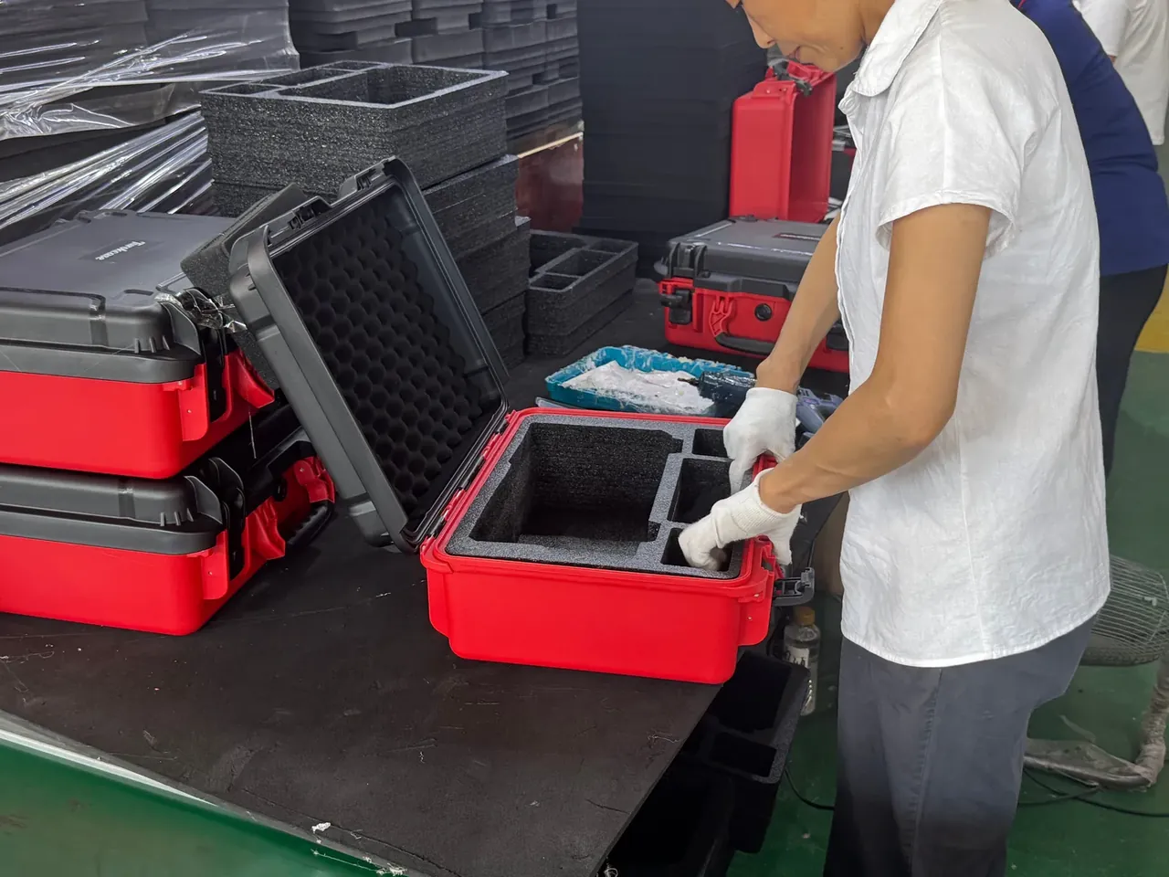
Two cases from one batch measure 452 mm and 448 mm along the cavity. Foam cut to 450 mm must be squeezed 2 mm into the small one, so the lid never closes flush, and it rattles 2 mm in the large one.
The same 4 mm means three things: on cavity length it hits the liner, on tongue depth it hits sealing, on hinge boss spacing it hits lid alignment. All three are case dimensional tolerance, yet each needs its own gauge.
A ±2 mm drawing allows 448 to 452 mm; a ±0.5 mm drawing allows 449 to 451 mm. Same nominal, four times the band, so a note reading "±2" tells the liner cell nothing.
2. Injection moulding and rotomoulding
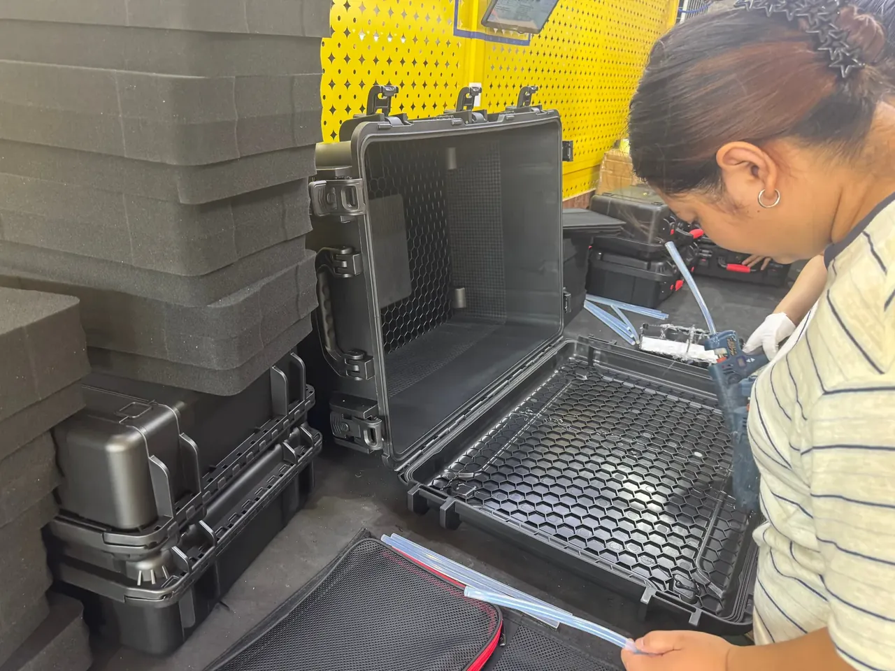
Injection moulding builds tolerance from mould precision plus shrinkage compensation. ABS shrinks 0.4% to 0.7%, so a 500 mm dimension is cut at 502.8 mm; shrinkage scatter of ±0.03% adds ±0.15 mm and mould temperature drift from 60 to 64 °C adds ±0.1 mm, so ±0.5 mm is achievable but not cheap.
Rotomoulding starts elsewhere. A steel mould at 260 to 300 °C expands 6 mm over 2 m, and powder shrinks 2% to 3% while a 6 mm section cools out of step with a 9 mm one, so ±2 mm on a 2 m case is good control.
The choice is a process boundary, not a precision contest: ±0.5 mm means injection moulding at ±2 °C, a 2 m single-piece shell means rotomoulding at ±2 mm.
| Process | Long side mm | Achievable mm | Control |
|---|---|---|---|
| Injection ABS | up to 300 | ±0.3 | Mould at ±2 °C |
| Injection ABS | 300–600 | ±0.5 | Mould at ±2 °C, 24 h |
| Injection PP | 600–1000 | ±1.0 | Two-stage packing |
| Rotomould PE | 1000–2000 | ±2.0 | Steel tool, stable shop |
| Rotomould PE | over 2000 | ±3.0 | Split tool, water cooled |
3. Lid joint and sealing face
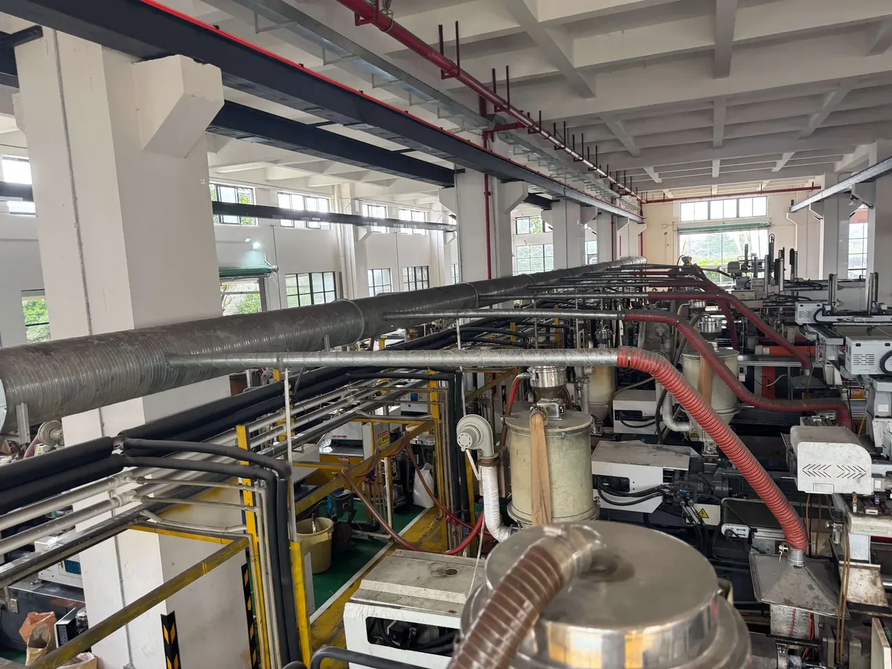
Sealing runs on compression, and compression is calculated, not assembled. A 4.0 mm silicone cord in a 2.6 mm groove gives 1.4 mm of squeeze, or 35%, the usual IP67 point; below 25% nothing seals and above 45% the cord takes a set.
Case dimensional tolerance subtracts from that. At ±0.5 mm per half the stacked band reaches 1 mm, so groove depth runs 1.6 to 3.6 mm and squeeze 0.4 to 2.4 mm, or 10% to 60%. Assembly size is a sum of parts, so tolerances add rather than average out.
The fix is structural: cut the groove in the lower shell and locate on a tongue, so depth comes from one part and ±0.5 mm maps to 22.5% to 47.5% compression.
| Tolerance case | Groove mm | Squeeze mm | Compression % | Verdict |
|---|---|---|---|---|
| Nominal | 2.6 | 1.4 | 35 | Pass |
| Single half ±0.5 | 2.1–3.1 | 0.9–1.9 | 22.5–47.5 | Marginal |
| Both halves ±0.5 | 1.6–3.6 | 0.4–2.4 | 10–60 | Leaks or locks |
| Single half ±2 | 0.6–4.6 | −0.6–3.4 | 0–85 | Unusable |
At ±2 mm the worst groove is 4.6 mm, deeper than the cord, so the seal never touches the lid; the opposite leaves 0.6 mm and crushes the cord 85%.
4. Liner fit clearance
Foam allowance and cavity tolerance are a pair: too little lets foam shift, too much forces it in and EVA collapses.
At ±0.5 mm, cut foam to nominal with 0.5 mm of interference per side, and movement stays under 0.5 mm, so holes line up. At ±2 mm the interference must be 1.5 mm, compressing the foam 20% on entry and lifting density from 45 to 56 kg/m³, which shifts the cushion curve upward.
Locating holes differ. A ±0.5 mm case takes 0.2 mm of clearance per side and survives 200 insertions; at ±2 mm the pin needs 0.8 mm and wears the hole oval after 100 km of mountain road.
Temperature adds a layer. PE expands at 1.5×10⁻⁴ per kelvin, so a 1 m cavity grows 6 mm from 20 to 60 °C, more than a ±2 mm band, and hot-service liners must be cut against the 60 °C cavity.
5. Inspection and gauge capability
Measuring ±0.5 mm work with a caliper is close to measuring nothing. A digital caliper resolves 0.01 mm and repeats within 0.03 mm, but 0.05 mm of uncertainty is a tenth of the band.
Choose gauges on a 1:10 ratio of tolerance to uncertainty: ±0.5 mm needs uncertainty under 0.05 mm, so volume work needs a go/no-go fixture at 12 s per part, while ±2 mm tolerates a caliper.
A CMM takes 8 minutes for five points and suits disputes; a laser scan returns a cloud in 3 minutes and reads joint mismatch, which is a continuity error.
One trap sits in the clock: a moulded part keeps shrinking for 30 minutes after ejection, up to 0.3 mm at 500 mm, so judge it after 24 hours.
| Gauge | Resolution mm | Repeatability mm | Five points | Applies to |
|---|---|---|---|---|
| Digital caliper | 0.01 | 0.03 | 90 s | ±0.3 and wider |
| Micrometer | 0.001 | 0.005 | 120 s | ±0.05 and wider |
| Go/no-go fixture | 0.05 | 0.02 | 12 s | ±0.5 in volume |
| CMM | 0.001 | 0.003 | 8 min | First article |
| Laser scan | 0.02 | 0.05 | 3 min | Joint mismatch |
Treat the last column as a floor, since narrower bands leave less room for gauge uncertainty.
Conclusion
Run two acceptance schemes. For ±0.5 mm cases, measure 18 points on the first article, then pull 5 parts every 2 hours against cavity length, cavity width and joint mismatch. For ±2 mm cases, sample 8 per batch, or follow GB/T 2828.1 level II at AQL 1.0, where a 500-piece lot maps to 32 samples.
Match gauges to the band: fixtures at ±0.5 mm, calipers at ±2 mm, a CMM when the argument starts. Case dimensional tolerance left off the drawing leaves inspection no decision line.
This article discusses container-side specifications and design implications only, and does not cover any handling, loading or use of the contents.
Related Reading
- How to measure the net cavity
- Dimensions to confirm at trial moulding
- Gasket groove cross-section design
- Incoming waterproof test acceptance
Related Products
- 8 Series — Gun Cases; Military Equipment Cases; Camera Equipment Cases; Drone Cases; Watch Cases; Knife Cases; First Aid Cases; Electronics Equipment Cases
- WL8-2812 PP Gun Case — model WL8-2812
- All protective cases and toolboxes: 7 series, 158 models