

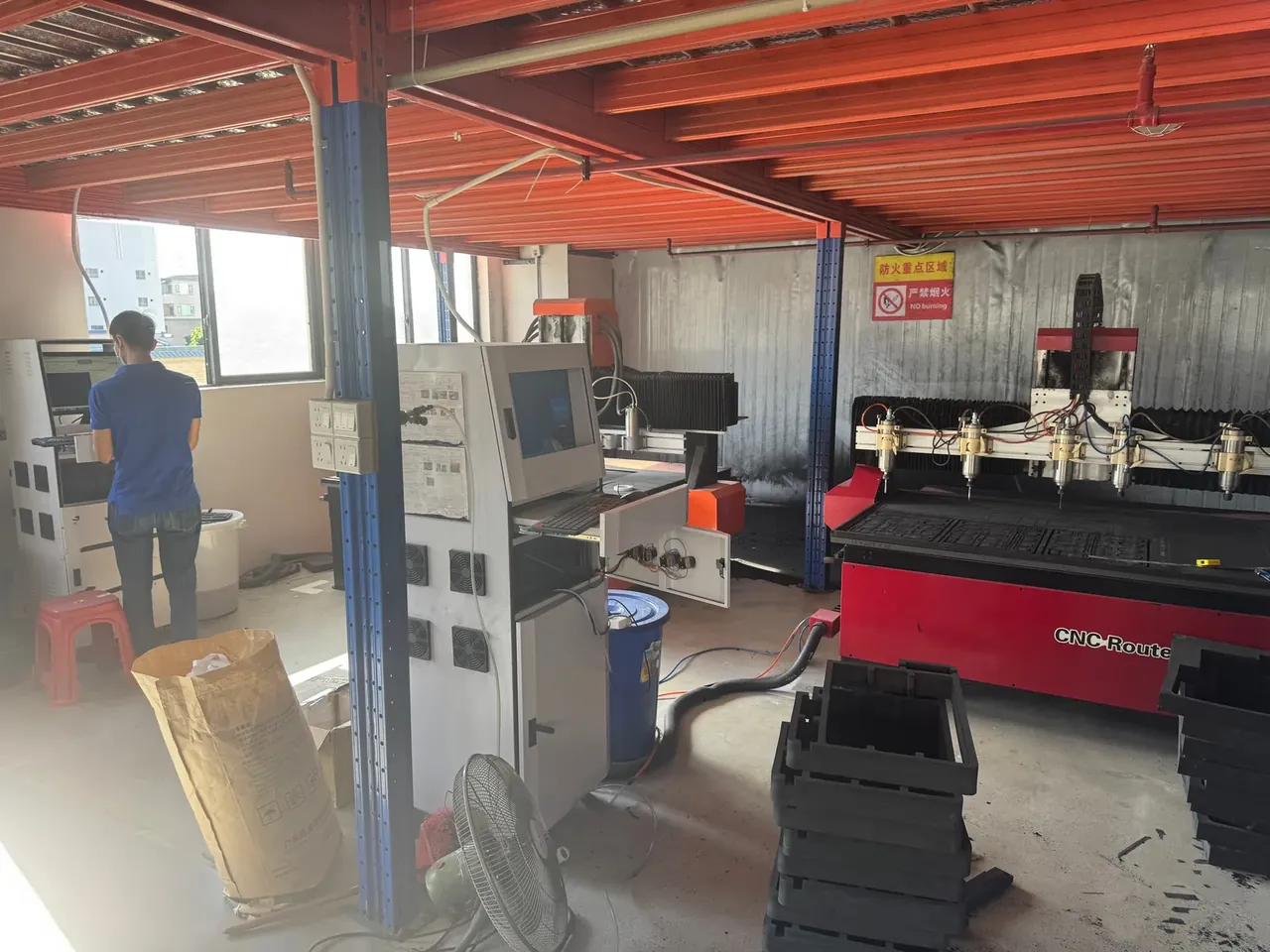
Quick answer: CNC Insert Cutting ties three settings: φ3 at 1800 mm/min, φ6 at 2400 mm/min, three layers at 45 mm, all held to 0.15 mm burr.
Table of contents
- Picking a Blade Diameter
- Feed Rate and Edge Burr
- Stack Height and Cut Squareness
- Tool Wear and Compensation
- Parameter Setpoints for Batch Inserts
- FAQ
1. Picking a Blade Diameter
On one EVA sheet, a 3 mm blade at 1800 and a 6 mm blade at 2400 leave burrs that differ by a factor of two. At 45 kg/m³ the foam is soft and closed-cell, so an edge compresses before it shears. CNC Insert Cutting therefore starts at the smallest inner radius, not at the fastest cycle.
A 1.5 mm corner needs a φ3 tool; a φ6 tool carries a 3 mm tip radius and leaves a rounded notch, so the insert sits 1.5 mm off the equipment. Outer profiles have no such limit, and one φ6 pass replaces two φ3 passes.
Flute count matters too. A single-flute spiral clears swarf; a multi-flute tool clogs within a few hundred millimetres once the foam warms, then rubs instead of cutting.
Widen the blade and the fit inside the case shifts. An insert sits 0.5 mm inside the case cavity, and the corner arc of a φ6 tool eats half that clearance.
| Blade tier | Typical use | Depth per pass | Watch out |
|---|---|---|---|
| φ2 mm | Fine cut-outs, narrow slots | 8 mm | Snaps easily; feed down to 1200 mm/min |
| φ3 mm | Inner corners, general profiles | 15 mm | Stay clear of radii under 1.5 mm |
| φ6 mm | Outer profiling, large arcs | 15 mm | Never enters a corner; leave 0.3 mm |
2. Feed Rate and Edge Burr
Feed decides how long the edge dwells. In CNC Insert Cutting, at 18000 rpm and 1800 mm/min a φ3 tool advances 0.1 mm per revolution and slices; at 900 mm/min it scrapes, the foam softens and the edge pulls into threads.
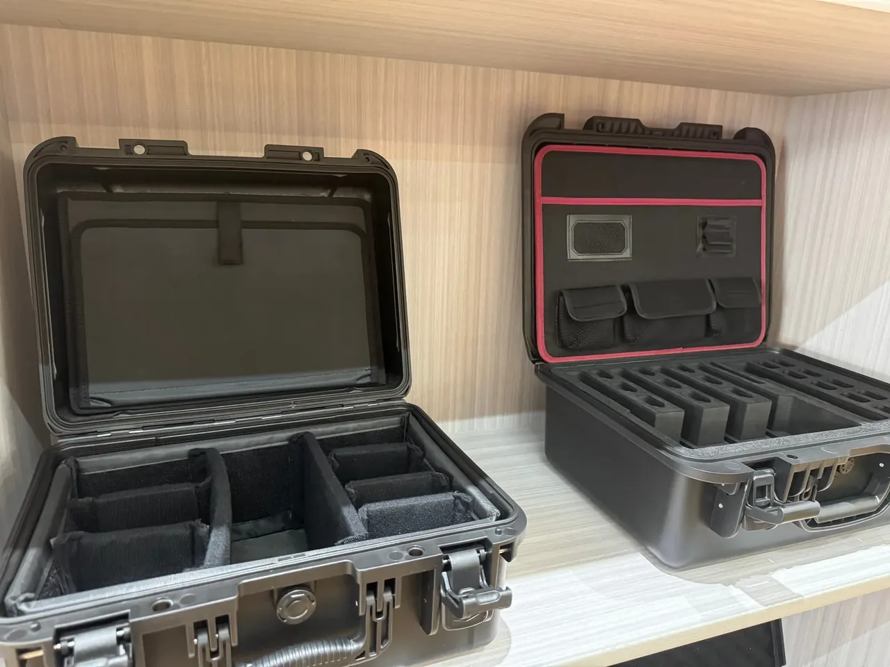
Burr is held to 0.15 mm. Hold the cut against a light and read the hanging fibres under a loupe, then re-check at every roll change, since a new batch has a different cell size.
Hold-down shows in the burr as well. When vacuum slips, the sheet lifts a little and a step appears in the upper half of the cut; a backing board under thin stock holds better than clamps do.
Deep inserts in CNC Insert Cutting need a slower feed: the shank reaches further into the case profile, so 1800 mm/min drops to 1500 mm/min or the lower cut deflects.
3. Stack Height and Cut Squareness
In CNC Insert Cutting, three layers at 45 mm, 15 mm each, is the standard batch. Stack higher and the shank reaches further, the bottom swings, and squareness slides from 0.12 mm to 0.20 mm, which is where an insert still presses into place. Match layers first. One density, one cell direction, tape at the corners. The bottom sheet sits flat on the table, because a first layer off square takes the other two with it. Zero the tool on the top layer rather than the table, since 45 mm of foam compresses under the probe.
| Stack order | Layers | Total height | Squareness | Batch fit |
|---|---|---|---|---|
| Single | 1 | 15 mm | 0.12 mm | Samples, deep pockets |
| Double | 2 | 30 mm | 0.16 mm | Medium runs, standard inserts |
| Triple | 3 | 45 mm | 0.20 mm | Volume runs, flat inserts |
From the fourth layer the shank lacks rigidity, burr and squareness fail together, and the hours saved are fewer than the rework they cause.
Stack height also matches the case opening: a 460 mm clear mouth takes 466 mm sheet, leaving 3 mm each side for tape and clamps.
4. Tool Wear and Compensation
A worn edge cuts a narrower kerf, so the insert binds in the case. Wear is tracked to 0.08 mm; at that point the table takes 0.05 mm of compensation and the path shifts outward.
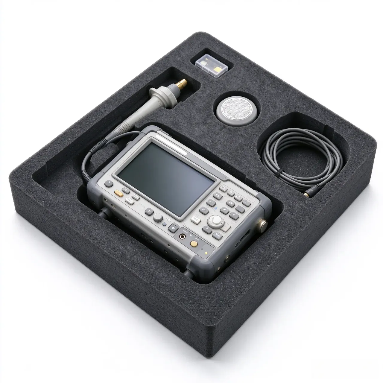
Compensation has a ceiling: past 0.15 mm of wear the edge is round and no offset cuts clean. The offset sits in the program header, and the first part of each shift is measured on three features, all inside ±0.3 mm.
Tools change by metres, not days: 400 m in soft foam and 250 m in dense foam for one φ3 blade. Wipe the collet face each time, since a tool clamped off true wobbles.
After any offset change, cut one part and try it. Four sides touching with no drag is the pass condition; two tight sides mean the shank is deflecting, and CNC Insert Cutting tables cannot correct that.
5. Parameter Setpoints for Batch Inserts
The batch sheet reads: φ3 at 1800 for corners, φ6 at 2400 for profiles, three layers at 45 mm, 6.5 min per part, on a 30 mm insert.
CNC Insert Cutting sheets split by blade into three columns, each with a single and a triple row, so the operator looks up the case model instead of converting numbers. The header states 45 kg/m³ as the base density.
The blade tier is the largest whose third-layer burr stays under 0.15 mm; anything wider is kept for single-layer roughing.
| Burr reading | Blade | Feed | Action |
|---|---|---|---|
| 0.08 mm | φ3 | 1800 mm/min | Release as is |
| 0.12 mm | φ3 | 1600 mm/min | Check hold-down, then release |
| 0.15 mm | φ3 | 1800 mm/min | Boundary value, change tool and retest |
Then the work is holding those numbers, the part of CNC Insert Cutting that never automates: first part of the shift, one part in 50, and the first part after a roll change, with readings written on the back of the sheet.
Conclusion
CNC Insert Cutting is read as a set: diameter fixes the corner, feed fixes the burr, stack fixes the squareness. Hold those against the 0.15 mm and 0.20 mm lines and the 6.5 min cycle stands. Posting the sheet is only the start; someone still has to measure at the first part, the fiftieth and the roll change.
Related Reading
Related Products
- 8 Series — Gun Cases; Military Equipment Cases; Camera Equipment Cases; Drone Cases; Watch Cases; Knife Cases; First Aid Cases; Electronics Equipment Cases
- WL8-2812 PP Gun Case — model WL8-2812
- All protective cases and toolboxes: 7 series, 158 models