

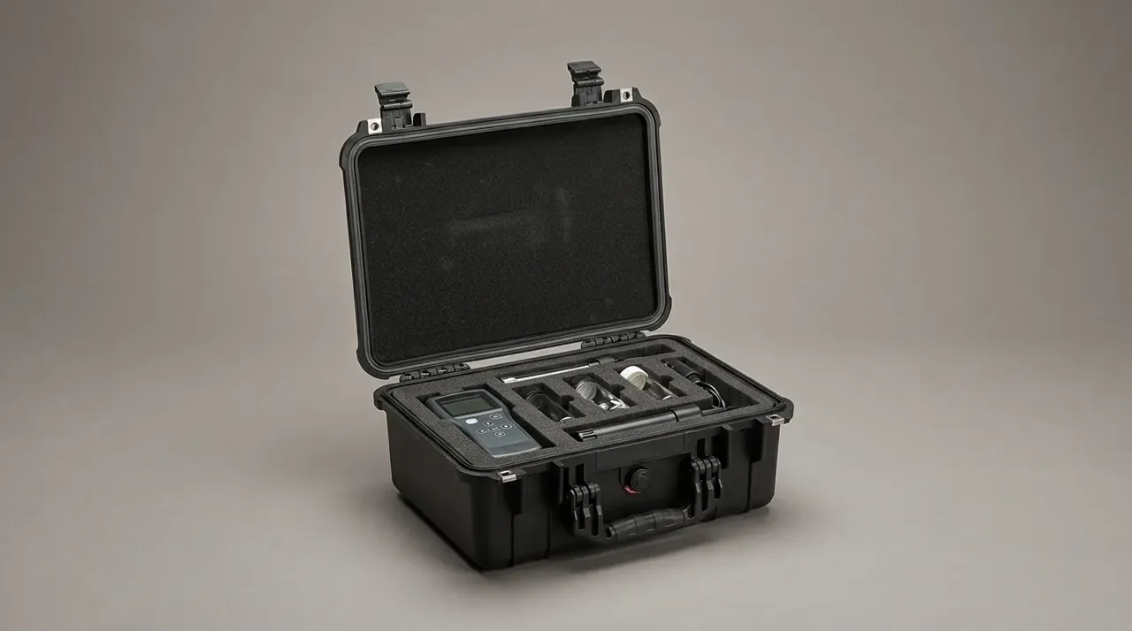
Quick answer: A diving waterproof dry box plastic hard shell keeps water out through three details: a 4 mm gasket compressed 25%, a 4 mm wall that carries 2 m of depth, and a valve that equalises at 3 kPa without letting water in. If one is off, a 1 m, 30-minute immersion leaves a trace.
Table of contents
- Shell Structure and Wall Thickness
- Gasket Cord and Compression
- Pressure Valve and Latch Force
- Foam, Ballast and Buoyancy
- Immersion and Pressure Test Lines
- FAQ
1. Shell Structure and Wall Thickness
Treat the shell as a pressure vessel. Every 10 m adds about 100 kPa, so 2 m gives 20 kPa, which on a 300 by 200 mm lid becomes 1,200 N pushing inward. A domed panel turns that into membrane stress and saves half the wall.
Thickness follows volume: below 3 L, 3.0 to 3.5 mm; 3 to 8 L, 3.5 to 4.0 mm; above 8 L, 4.0 to 4.5 mm plus a 6 mm base rib at 70 mm spacing. Each extra 0.5 mm adds about 8% to weight while buoyancy barely moves.
Corner radius is easier to neglect than wall. Under 6 mm the melt shears and cracks start there on the first drop; an 8 mm radius with a 2° draft keeps stress concentration below 1.3.
The mouth flange takes the highest load: 12 mm wide, 3 mm thick, with a 1.5 mm step so the lid centres before the gasket compresses. Past 0.2 mm flatness, the drop goes from 0.2 to 0.6 kPa.
| Usable volume | Wall | Base rib | Empty weight | Working depth |
|---|---|---|---|---|
| Under 3 L | 3.0–3.5 mm | 4 mm | 0.9 kg | Up to 1 m |
| 3–8 L | 3.5–4.0 mm | 6 mm | 1.8 kg | Up to 2 m |
| Over 8 L | 4.0–4.5 mm | 6 mm | 3.2 kg | Up to 3 m |
2. Gasket Cord and Compression
The seal is a continuous line, not a ring of even pressure. An O-ring gives its widest contact band at 22% to 28% flat. Below 20% the band breaks; above 32% the rubber takes a permanent set.
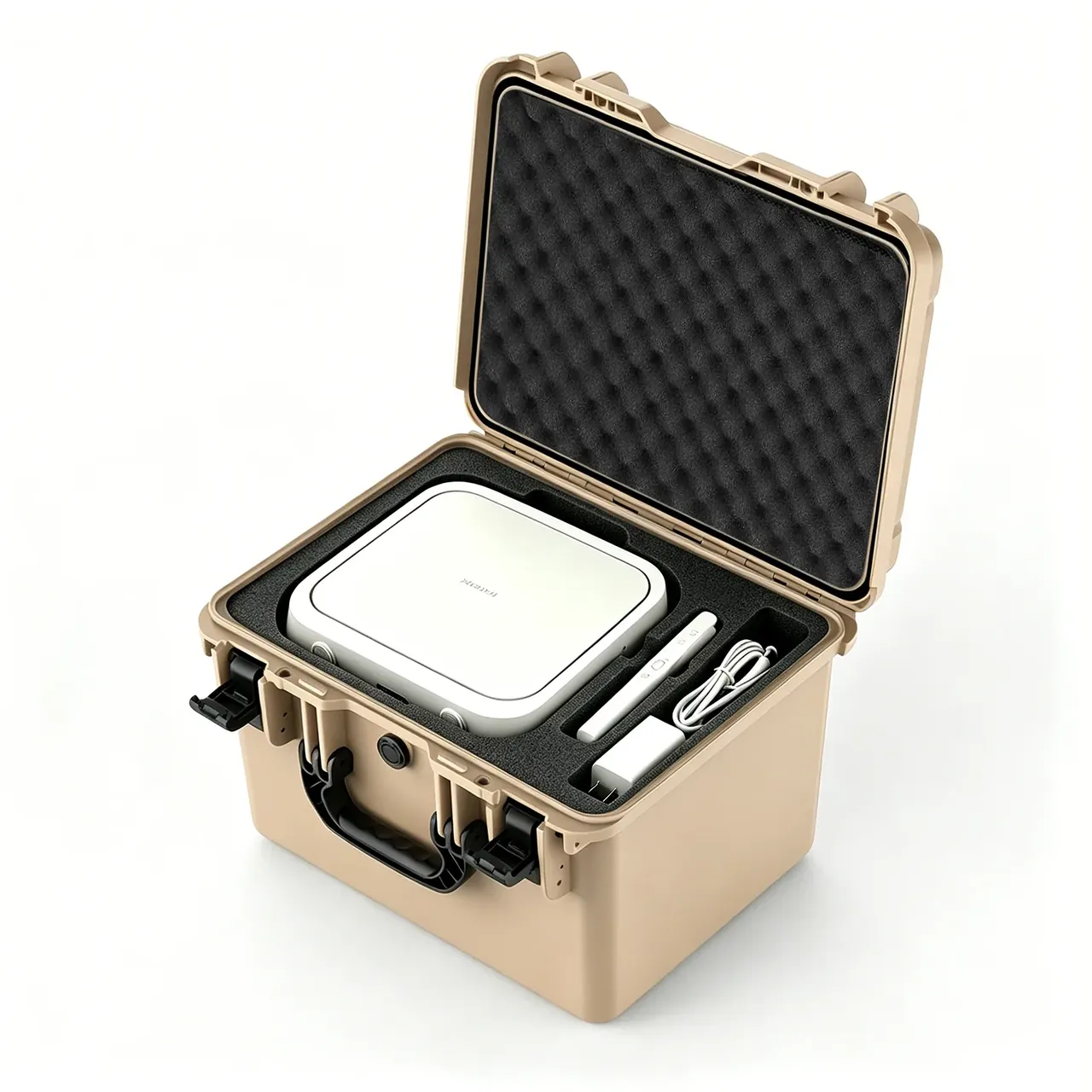
Cord diameter sets tolerance. A 3 mm cord sits in a 4.0 by 2.2 mm groove; a 4 mm cord sits in a 5.2 by 3.0 mm groove, giving 25% compression and tolerating 0.15 mm of waviness. Thicker cord forgives more but raises closing force.
Corners leak first. Mitre all four at 45°, cut a 0.5 mm locating groove and press the splice for 24 hours. A cord bent around a corner splits at the bend within three months.
Fill ratio is groove area minus cord area over groove area: 75% to 85%. Under 75% the rubber rolls; over 85% it lifts the flange by 0.1 mm and the leak starts.
| Cord | Groove width | Groove depth | Compression | Flange tolerance |
|---|---|---|---|---|
| 3.0 mm | 4.0 mm | 2.2 mm | 26% | 0.10 mm |
| 4.0 mm | 5.2 mm | 3.0 mm | 25% | 0.15 mm |
| 5.0 mm | 6.5 mm | 3.8 mm | 24% | 0.20 mm |
Compound follows temperature. Silicone covers -60 to 200 °C with good rebound and resists salt water; EPDM handles ozone and UV at about 30% lower cost.
3. Pressure Valve and Latch Force
A valve equalises pressure, not water. Air inside changes with temperature: 60 °C by day and 10 °C at night puts about 10 kPa across a 6 L cavity. The valve opens at 3 to 5 kPa so latches never carry that load.
Flow rate sets venting speed: a diaphragm valve passes about 0.5 L/min at 3 kPa, so a 6 L cavity equalises in 12 seconds. Mount the valve on an 8 mm flat pad, never on a radius.
Latch force and compression are one account. A single latch pulls 80 N, four give 320 N, about 800 N per metre across a 400 mm seal line, enough for 25% compression. Overtighten and the gasket seats dead; leave it loose and the drop passes 0.3 kPa in 30 seconds.
Hinges are not load paths but they eat compression. Four-segment hinges need 0.2 mm of axial clearance; under 0.1 mm the gasket reaches 18% and the hinge side leaks.
4. Foam, Ballast and Buoyancy
Buoyancy comes before foam. A 6 L box displaces 6 L, about 60 N of lift; empty at 1.8 kg it weighs 18 N, leaving 42 N net. Load past 60 N and it sinks, so add ballast or step down a size.
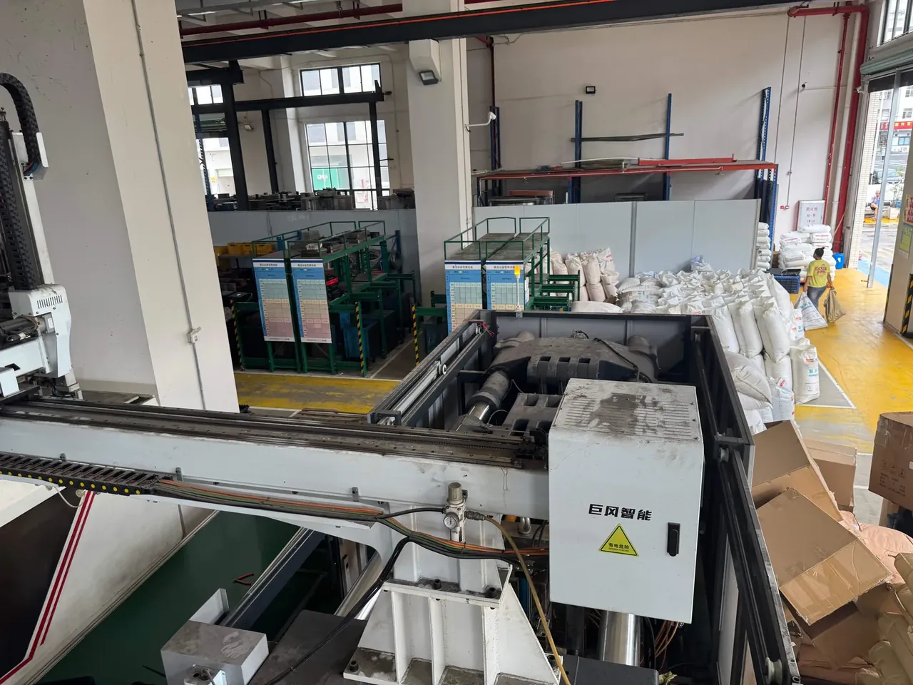
Choose closed-cell foam. Open-cell sponge soaks up to 30 times its weight and collapses the buoyancy sum after one dunk. Closed-cell EVA absorbs under 1% and gains less than 2 g in a 24-hour soak.
Cut the foam by subtraction: a 120 mm cavity takes a 20 mm closed-cell base pad, 10 mm side interference, the rest for the load. Any gap between foam and wall becomes travel that works the gasket off its land.
Handles need their own numbers: one carries 25 kg static, twice that for dynamic load, and the eye goes on a 20 mm solid boss. Bolt through a thin panel and the first lift dishes the wall.
5. Immersion and Pressure Test Lines
One sample proves nothing. Read immersion, pressure and temperature together; each hides a different failure path.
| Test | Condition | Pass line |
|---|---|---|
| Air | 3 kPa for 60 s | Drop under 0.3 kPa |
| Immersion | 1 m for 30 min | No water, gain under 2 g |
| Vessel | 0.05 MPa for 10 min | No seepage or set |
| Drop | 1.2 m, six faces, -20 °C | No cracks, latches closed |
| Cycling | -20 to 60 °C, 5 cycles | Set under 20% |
Run air, then the vessel, then drop. Drop first and internal craze fails the air test, so design faults and impact damage look alike. The 0.05 MPa vessel equals 5 m of water, twice the rating.
Sample air and weight gain at AQL 2.5, and pull three units per batch for drop. Add 3% salt to the tank, or fresh water understates the osmotic load.
Conclusion
Set depth and volume first, then derive wall and rib; size the groove from the cord and fix compression by fill ratio; check the pressure differential before placing the valve; then write air, vessel, immersion and drop into the drawing. Choose the gasket before the wall and the tool pays for it.
This article covers container-side specifications and design implications only.
Related Reading
- Waterproof hard case grades and structural checks
- How a dry box differs from a protective case
- Dry bags and hard dry boxes compared
- Why 0.3 kPa marks the airtight limit
Related Products
- 8 Series — Gun Cases; Military Equipment Cases; Camera Equipment Cases; Drone Cases; Watch Cases; Knife Cases; First Aid Cases; Electronics Equipment Cases
- WL8-2812 PP Gun Case — model WL8-2812
- All protective cases and toolboxes: 7 series, 158 models