

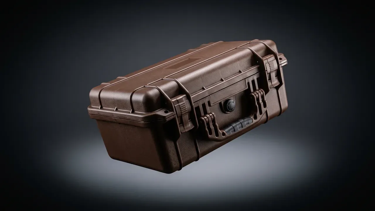
Quick answer: An Electronic Equipment Case wall is derived, not chosen: cavity from the equipment outline plus allowance, wall from lid span and stack load, stiffness from rib height, sealing from groove depth. Miss one link and the case returns either sagging or leaking.
Table of contents
- Where the Cavity Starts: Outline Plus Three Allowances
- A 14 kg Load on the Lid Sets the Wall
- Ribs at 16 mm and 130 mm Restore Stiffness
- Latches Follow the Perimeter, Hinges the Cavity
- Groove Depth Is 0.72 Times the Cord Diameter
- Five Steps Written as a Delivery Specification
- FAQ
1. Where the Cavity Starts: Outline Plus Three Allowances
A cavity is not a number you scale up until it looks generous. It is the widest outline of the equipment, a per-side allowance, and the millimetres of foam that compress when the lid closes, added together. Write all three and the cavity has one answer; leave the allowance out and three factories quote three sizes sharing nothing.
The allowance has three bands, set by the face rather than by habit. A flat panel takes 8 mm. A face with plugs, switches or a vent grille takes 12 mm, because plugs stand proud and are the first thing missed on a drawing. A face wired on site takes 10 mm plus a cable port. That is the difference between getting an insert in and getting a hand in.
| Equipment outline (L x W x H) | Per side | Cavity | Outside | Volume |
|---|---|---|---|---|
| 300 x 210 x 120 | 8 mm | 316 x 226 x 136 | 372 x 282 x 186 | 9.7 L |
| 360 x 280 x 150 | 10 mm | 380 x 300 x 166 | 440 x 360 x 216 | 18.9 L |
| 420 x 310 x 165 | 10 mm | 440 x 330 x 185 | 505 x 395 x 235 | 26.9 L |
| 520 x 380 x 200 | 12 mm | 544 x 404 x 220 | 610 x 470 x 274 | 48.4 L |
The outside runs 28 to 33 mm wider than the cavity per side: half wall, half lid overlap and latch keepers. That gap is stable, so a fixed cavity fixes the outside almost by itself. The reverse never works.
Height is a separate addition, at least 15 mm above the unit for plug bodies and cable bend radius. Corners start at R10. Below R8 the powder bridges, the corner wall reaches 1.4 times nominal, one side runs heavy and the uneven shrink drags the lid face out of flat. Hold the cavity to plus or minus 1.5 mm and bias it positive: foam fills a gap but cannot remove interference.
2. A 14 kg Load on the Lid Sets the Wall
A 14 kg field logger, a 30 mm EVA insert at 2.1 kg and a 5.6 kg body make one packed case of 21.7 kg. Stacked three high, the bottom lid carries the two above: 43.4 kg, about 425 N, over a 440 x 330 mm face.
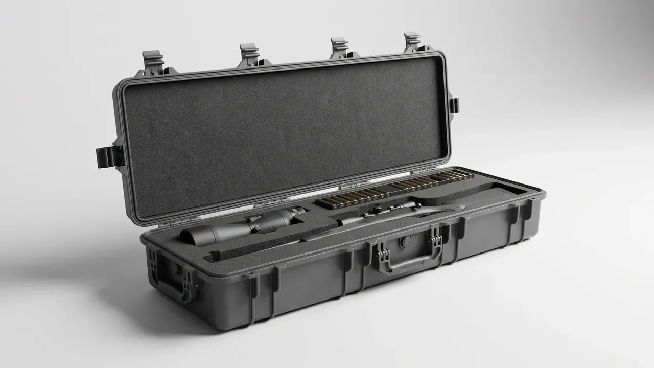
Treat the lid as a simply supported plate. Span is 330 mm, and 425 N over 145,200 mm2 gives 0.0029 N/mm2. With high density polyethylene at 900 MPa, a flat 5.5 mm lid deflects in the region of 9 mm, while the usual limit of span over 150 allows 2.2 mm. That gap cannot be bought with wall alone: deflection falls with the cube of thickness, so 2.2 mm needs 8.8 mm, which adds 2.6 kg and stretches the rotomoulding cycle from 22 to 33 minutes. Hence ribs first, letting section inertia carry the load, and a small wall increase second. It also explains why two cases both stamped 5.5 mm behave differently: one takes three high, the other sags in the second layer, and the ribs are the whole difference.
| Packed weight | Cavity short span | Flat lid needs | Ribbed wall | Rib height x pitch |
|---|---|---|---|---|
| Under 8 kg | Up to 260 mm | 4.0 mm | 3.0 mm | 12 x 110 |
| 9 to 18 kg | 261 to 340 mm | 9.0 mm | 6.0 mm | 16 x 130 |
| 19 to 35 kg | 341 to 420 mm | 11.0 mm | 7.0 mm | 20 x 150 |
| 36 to 55 kg | Above 421 mm | 13.5 mm | 8.5 mm | 24 x 170 |
The third column is a proof by contradiction rather than a recommendation. An unribbed case would have to be that thick to pass, and an 11 mm rotomoulded shell is uneconomic in weight and cycle time. That column is the argument for ribs.
Once 6 mm is fixed, the job is holding it. A rotomoulded part carries plus or minus 15 per cent, so 6 mm means 5.1 to 6.9 mm, and panels that sit at 5.1 for a year are where sag begins.
3. Ribs at 16 mm and 130 mm Restore Stiffness
A rib does not thicken the wall; it moves the load path from mid-lid out to the side walls. Section inertia grows with the square of rib height and barely notices width, so height is the cheaper lever.
- Height at 2.7 times the wall: 16 mm on a 6 mm shell, and past 20 mm the root sinks
- Pitch near 130 mm: beyond 170 mm the lid between ribs bows on its own
- R3 at the root, R2 at the crest: powder will not pack a sharp corner and leaves a 0.5 mm void
- One direction only: a crossing node runs 1.8 times nominal, cools slowly and dishes the lid
- Ribs square to the handle: carrying load runs along the handle, so a parallel rib does nothing
The inertia works by hand. Take a 130 mm wide strip: a 6 mm flat section gives 2,340 mm4. Add a 5 mm wide, 16 mm rib and shift its area to 11 mm off the neutral axis, and the value reaches about 13,700, near six times the flat figure. Six times the inertia means one sixth the deflection, so 9 mm becomes 1.5 mm; measured figures usually land near 2 mm, the rest being local distortion at the lid edge that latches and overlap must cure.
Height has a ceiling, and it differs by process. Move the same case to injection moulding and the rib root may only be 0.6 times the main wall, with height capped at three times the root, so 6 mm allows a 10 mm rib. That is why rotomoulding saves wall through rib height and injection has to add rib count instead.
4. Latches Follow the Perimeter, Hinges the Cavity
One latch every 400 to 450 mm of lid perimeter, minimum two. A 440 x 330 cavity gives a 505 x 395 outside and an 1,800 mm perimeter, which lands on four. Corners are already stiff nodes, so four spaced along the long sides beats a fifth on a short side.
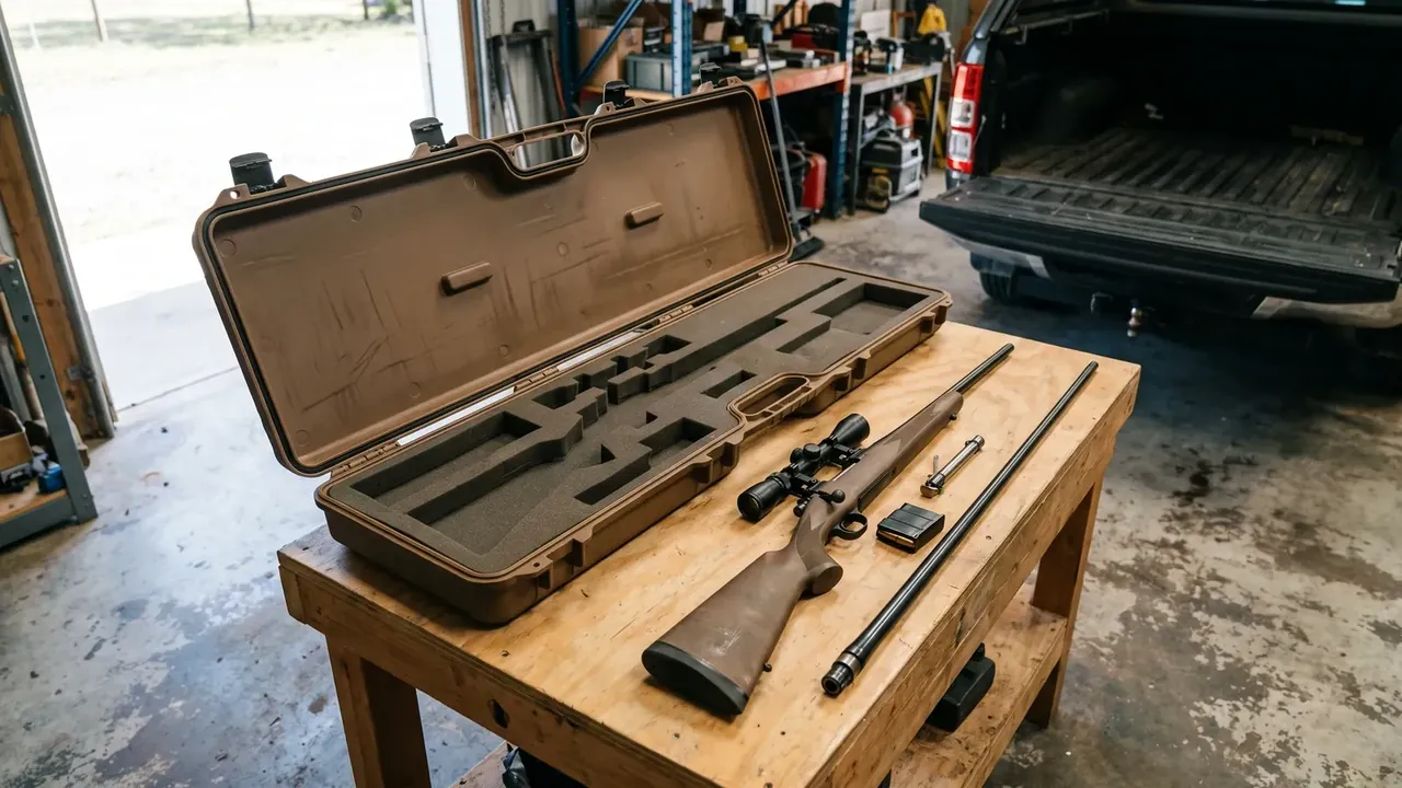
Engagement depth matters more than body strength. Set hook-to-keeper overlap at 6 mm and the keeper root at 4 mm or more. A latch with 4 mm of overlap slides open under side impact, and thickening the body buys nothing.
Hinges follow cavity length. Above 400 mm, two hinges on a 6 mm pin with molybdenum-filled nylon bushes; between 300 and 400 mm, one long hinge with two dowels; below 300 mm, a continuous hinge. A 4 mm pin bends the first time a 30 kg load is lifted by the lid, and once bent the lid never closes flat again. Boss thickness deserves its own line on the drawing: it gets quoted as wall, yet it is the most concentrated load path in the case, and 8 mm is the floor.
5. Groove Depth Is 0.72 Times the Cord Diameter
A groove cannot be cut to the outside diameter of the cord. A solid EPDM cord wants 26 to 32 per cent compression: below 26 per cent it never seats, above 32 per cent it is squeezed out and sliced by the closing lid.
Three dimensions belong together. Width is cord diameter plus 0.3 mm, depth is diameter times 0.72, and the mouth carries an R0.5. An 8 mm cord sits in a 8.3 mm wide, 5.8 mm deep groove, stands 2.2 mm proud and loses 27.5 per cent when the lid comes down.
Flatness decides whether that compression is even. Hold the mating face to 0.2 mm; past 0.4 mm the compression mid-span drops below 15 per cent, and that is the spot that fails first in rain. Two grooves are not automatically safer either: a pair of 8.3 mm grooves eats 18 mm of lid edge and leaves the keepers thinner, while a single groove with a raised water lip measures more stable.
6. Five Steps Written as a Delivery Specification
A specification makes plant and buyer answer for the same numbers. Stating 6 mm wall alone means nothing; the sheet must say where it is measured, how much variation is allowed, and under what condition.
| Item | Value | Acceptance condition |
|---|---|---|
| Cavity | 440 x 330 x 185 mm | Lowest of three measurements, plus or minus 1.5 mm |
| Outside | 505 x 395 x 235 mm | Including keepers, excluding handle |
| Wall | 6.0 mm | Six-point ultrasonic, no point below 5.1 mm |
| Corner wall | 6.8 to 8.2 mm | Thick allowed, thin not |
| Tare | 5.6 kg | Without insert |
| Lid deflection | 2.2 mm max | 425 N distributed, read at 24 hours |
| Ribs | 3 one-way, 16 mm high, 130 mm pitch | No sink, no root voids |
| Latches | 4, 6 mm engagement | Keeper root 4 mm |
| Hinges | 2 sets, 6 mm pin | 5,000 loaded cycles without play |
| Seal groove | 8.3 mm wide, 5.8 mm deep | Takes 8 mm solid EPDM cord |
| Ingress rating | IP67 | 1 m for 30 minutes |
| Insert | 30 mm closed-cell EVA | 1 mm interference per side |
The column most often dropped is the third. At 425 N distributed, a reading after one hour differs from one after 24 hours by more than 30 per cent; IP67 at 1 m for 30 minutes is a different grade from 1 m for 24 hours. Without the condition, the value is a wish.
One number does not belong on the sheet at all: price. Once price enters a specification review, the argument circles it and nobody reads the tolerances.
Conclusion
The specification of an Electronic Equipment Case is a chain: cavity from outline and allowance, wall from lid span and stack load, stiffness from rib height, sealing from groove depth. Skip a link and it returns as a sagging lid or a wet interior. Written as twelve lines with acceptance conditions, that chain is worth more than thirty yuan argued off a quotation.
This article discusses only the container (case body) side of specifications and design intent, and does not cover any handling, loading or use of the contents.
Related Reading
- Shielding, grounding and heat paths in an electronic equipment case
- How rotomoulding distributes wall thickness
- Clamp force and rib design on an injection machine
- Dividers and foam compartments inside a case
Related Products
- 8 Series — Gun Cases; Military Equipment Cases; Camera Equipment Cases; Drone Cases; Watch Cases; Knife Cases; First Aid Cases; Electronics Equipment Cases
- WL8-2812 PP Gun Case — model WL8-2812
- All protective cases and toolboxes: 7 series, 158 models