

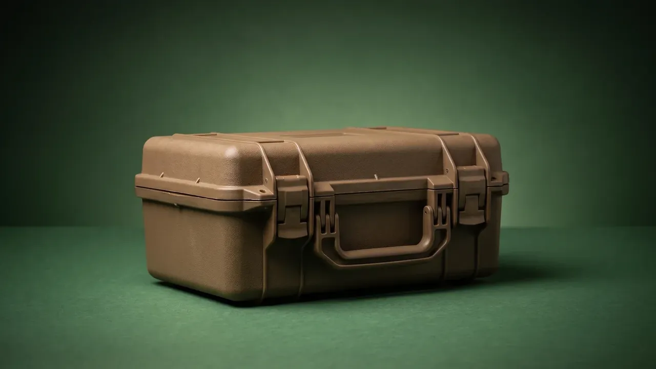
Quick answer: Moving radio and power units outdoors forces four decisions at once: cutout tolerance, sealing and shield bonding at cable entries, the vent path, and an earthed ESD liner. The limits are a hole position within 0.3 mm, gland torque of 2.5 N·m, an 8 °C internal rise, and a liner between 10^6 and 10^9 ohms.
Table of contents
- On the seawall: four gates in one installation
- Panel cutouts: where the tolerance band meets the tool
- Cable entries and glands: bonding the shield
- Vent cutouts: intake area and filter sized together
- ESD liner and rack mounting
- FAQ
1. On the seawall: four gates in one installation
June on the Zhejiang coast: a 5G base station stands with its cabin against the breakwater. The baseband unit and switching supply sat in an indoor rack where noon air reached 46 °C and the unit throttled once cooling stopped. The retrofit moved both into an electronic equipment plastic case of 620 by 480 by 260 mm on the wall at 1.2 m.
Getting the units in was never the problem: connectors through the panel, mains and fibre up through the base, eighty watts out of a sealed cavity, a module out within ninety seconds in wind.
| Gate | Field criterion | Frequent mistake |
|---|---|---|
| Panel cutouts | Gap round each connector under 0.1 mm, gasket even | Cut to nominal size, no shrink allowance |
| Cable entries | Gland at 2.5 N·m, cable will not shift | Sealant on the exit, cracks later |
| Heat | Internal air under 8 °C above ambient | Intake with no exhaust |
| Static and earth | 10^6 to 10^9 ohms, earth path under 0.1 ohm | Plain foam, wire not bonded |
The order cannot be shuffled: cutouts, cable, vent path, liner.
2. Panel cutouts: where the tolerance band meets the tool
The interface panel is the costliest block of tooling. The shell is modified PP at 3 mm wall, shrink at 0.6 percent, so a 620 mm electronic equipment plastic case loses close to 3.7 mm along its length; holes cut to drawing size walk on the first shots.
Twelve openings: eight M12, two M20 glands, two fibre flanges. Diameter holds to ±0.2 mm, position to ±0.3 mm; past that the gasket squeezes one side and gaps the other.
| Opening | Qty | Size and tolerance | Failure mode |
|---|---|---|---|
| M12 connector | 8 | 12.2 ±0.2 mm | Gasket compressed one side |
| M20 gland | 2 | 20.3 ±0.2 mm | Gland will not start, thread cracked |
| Fibre flange | 2 | 26 × 36 mm | Flange proud, fibre loaded |
Quote counterbore depth with the hole. The flange is 2 mm; a 1.8 mm counterbore seats it, a full 2 mm leaves it floating until four screws pull a white mark.
3. Cable entries and glands: bonding the shield
Cable entries leak more than any other feature. The shortcut is an oval hole, cable through, sealant smeared round it; six months on the compound cracks and water runs down the jacket.
The electronic equipment plastic case wants four steps, starting with the hole:
- A stepped hole, 0.3 mm over the gland thread, chamfered at 1 × 45 degrees.
- Nylon glands indoors, nickel-plated brass outdoors, nitrile seals.
- Torque to 2.5 N·m; past 4 N·m the seal takes a permanent set.
Shield bonding is the step that gets skipped. Where a switching supply's cable enters, the shield needs a 360-degree clamp on the inside face, not a braid soldered to the wall; above a few tens of megahertz that braid impedance is far too high.
Earth runs separately: an M6 stud at 6 N·m with a toothed washer biting through the coating, and a conductor of at least 4 mm² kept short. Paint makes a joint that reads fine on installation day and doubtful later.
4. Vent cutouts: intake area and filter sized together
Eighty watts in a sealed box has nowhere to go. Convection carries about half; the rest needs vents and often a fan, and the first hole drops the rating from IP67 to IP54.

Intake low, exhaust high on the opposite face, at least 120 mm apart so hot air climbs by itself. Open area runs about 18 percent of the projected face: under 10 percent the flow is short, over 25 percent the wall dents in handling.
Shape matters more than area. A straight hole admits water fastest; louvred slots angled down 15 degrees throw drops clear, and a 40 ppi filter behind them holds dust.
5. ESD liner and rack mounting
The liner does more than cushion. Bare boards and gold fingers sit inside, and hands, tools and the wall all carry charge, so the liner of an electronic equipment plastic case belongs between 10^6 and 10^9 ohms. Below that, discharge damages a device; above it, the surface insulates.
An electronic equipment plastic case liner needs:
- Cross-linked polyethylene foam, steady around 10^7 ohms.
- 10 mm thick, 1.5 mm interference at the pocket walls.
- Heat-sealed cut edges, and a 500 V test every six months.
Rack mounting is the second dimension that gets missed. A 19-inch module needs 465 mm between hole centres and 1 mm of drift stops it; a 5 mm aluminium plate in the base, four M6 bolts at 6 N·m, holds the pattern.
Conclusion
The difficulty sits in the interfaces, not the moulding: the cutout that decides how evenly a gasket is squeezed, the clamp and gland that let sealing and shielding hold together, the vent that stops a unit throttling in August. Draw those gates before the tool is cut, and an electronic equipment plastic case stays sealed through two monsoons.
This article discusses only the container (case body) side of specifications and design intent, and does not cover any handling, loading or use of the contents.
Related Reading
- Electronic equipment cases in test, field and transit use
- How an electronic equipment case is built
- Equipment case selection guide
- Where equipment cases are used
Related Products
- 8 Series — Gun Cases; Military Equipment Cases; Camera Equipment Cases; Drone Cases; Watch Cases; Knife Cases; First Aid Cases; Electronics Equipment Cases
- WL8-2812 PP Gun Case — model WL8-2812
- All protective cases and toolboxes: 7 series, 158 models