

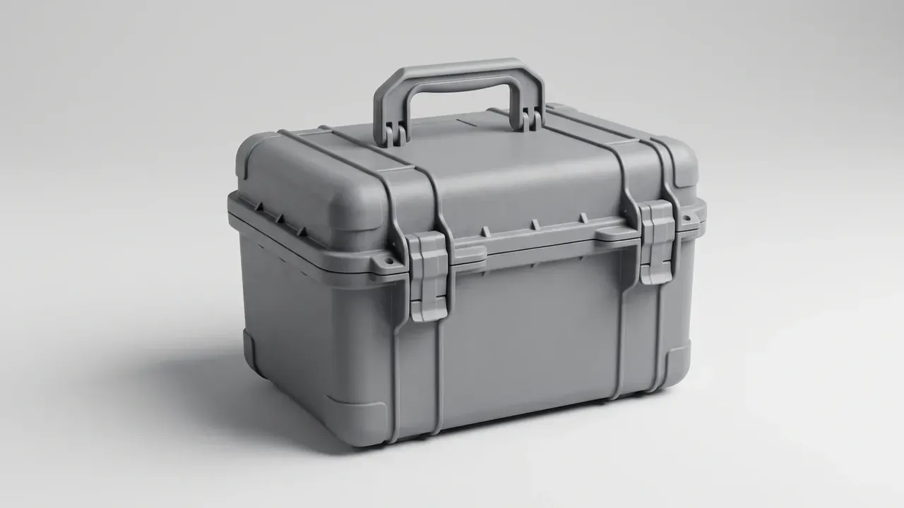
Quick answer: Electronic Measuring Instrument Case cavity runs from a 320×240×90 mm instrument to 390×300×150 mm through 25 mm foam and 0.5% shrinkage.
Table of contents
- Electronic Measuring Instrument Case cavity from the instrument outline
- Panel cutouts and key travel allowance
- Cable exit diameter and bend radius
- Wall, rib and cavity tolerance stack
- Interference checklist for the whole chain
- FAQ
1. Electronic Measuring Instrument Case cavity from the instrument outline
Selection starts with the instrument on the bench. A bench multimeter measures 320×240×90 mm, with three connectors standing 12 mm proud of the top face and 4 mm corner radii on its boot. Those numbers are what the Electronic Measuring Instrument Case has to swallow; miss one and the unit only goes in under force.
Depth runs as 90 mm of body plus 12 mm of connector, an 18 mm pad under the base, a 12 mm pad under the lid and 18 mm of handling clearance, which lands the cavity at 150 mm. Width takes 240 mm plus 20 mm of foam each side and 20 mm of side clearance for 300 mm. Length takes 320 mm plus 25 mm at each end and 20 mm of end clearance for 390 mm.
The wall is 3.2 mm and ribs are counted apart. ABS shrinks 0.4% to 0.7%, so a 390 mm cavity returns 1.6 mm to 2.7 mm smaller, about 1.95 mm at midpoint. The Electronic Measuring Instrument Case keeps shrinkage on its own line, because it drifts with melt temperature and packing pressure and cannot be told apart from tool error once merged.
| Chain element | Length | Width | Height |
|---|---|---|---|
| Instrument outline | 320 mm | 240 mm | 90 mm |
| Connectors and bosses | 0 | 0 | +12 mm |
| Cushion layer | 2×25 mm | 2×20 mm | 12 + 18 mm |
| Handling clearance | 20 mm | 20 mm | 18 mm |
| Cavity result | 390 mm | 300 mm | 150 mm |
2. Panel cutouts and key travel allowance
A 120×72 mm display window opens to 124×76 mm for a 2 mm overlap, and the hole edge must sit 8 mm from the outer wall; any thinner and water wicks along the rib root during 1 m / 30 min immersion. The panel is 2.5 mm, 0.7 mm under the wall, so the key skirt can press it down.
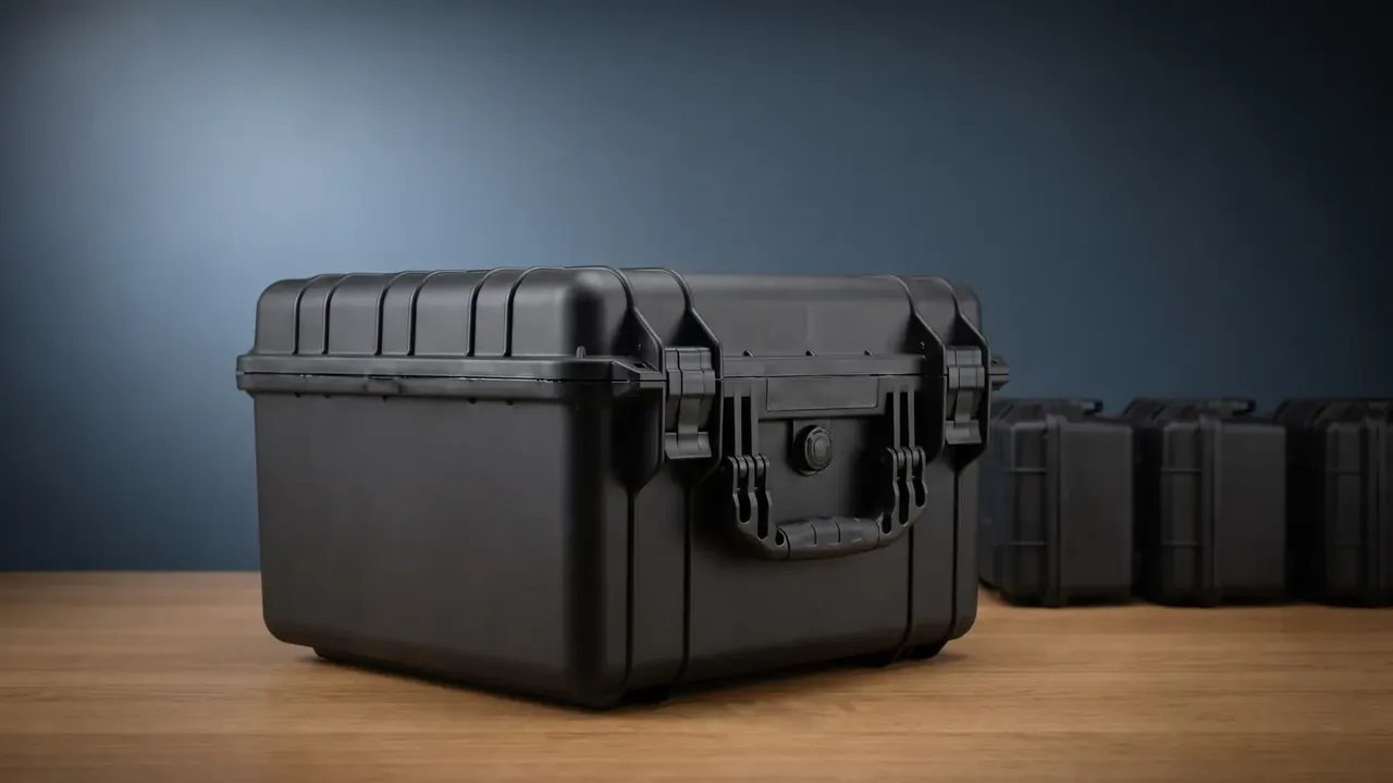
Key travel is 1.5 mm with a 3 mm recess behind the panel and a 1.2 mm silicone skirt. Openings and keys are checked on one flat pattern at ±0.2 mm; accumulate 0.5 mm across a row and the tool needs rework, since forcing it at assembly only leaves white marks.
Connector holes follow the body of each part: a 12 mm BNC flange takes 12.4 mm, a banana jack 8.2 mm, a USB port a 14×6 mm rectangle with 0.5 mm radii. A rib caught between two holes needs 3 mm of width or it sinks in moulding.
3. Cable exit diameter and bend radius
Exit bore is set by bend radius. An 8 mm lead needs 32 mm at four times its diameter, so the path from exit to cavity floor must hold that arc; fold it at the exit and the core fails after a few hundred flexes. The Electronic Measuring Instrument Case uses a 20 mm bore with an M16 gland covering 6 mm to 10 mm cables.
| Cable OD | Exit bore | Minimum bend radius | Gland |
|---|---|---|---|
| 5 mm | 14 mm | 20 mm | M12 |
| 8 mm | 20 mm | 32 mm | M16 |
| 12 mm | 26 mm | 48 mm | M20 |
A single exit sits 40 mm above the cavity floor, twin exits are spaced 25 mm with a 4 mm rib between, and a hole in the corner transition thins the wall to 2.2 mm, so it moves 15 mm onto the flat.
Unused exits take plugged O-rings sitting flush, with 0.1 mm of clearance: tighter will not assemble, looser weeps under immersion. One plug standing 0.3 mm high in a 20-case sample sends a batch back.
4. Wall, rib and cavity tolerance stack
A 3.2 mm wall cannot carry a 390 mm span alone. Ribs run 2.5 mm thick, 6 mm tall and no more than 90 mm apart, giving four longitudinal and two cross ribs, with a 0.5 mm root radius so the part releases without whitening.
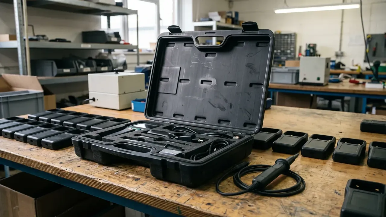
Tolerances read three at a time: cavity ±0.6 mm, foam cut ±1.0 mm and instrument outline ±0.3 mm, a worst case of 1.9 mm. The Electronic Measuring Instrument Case leaves 2 mm of interference so 8% compression absorbs it; past 3 mm of gap the unit starts to move.
Lid flatness is a separate line at 0.4 mm. Once it drifts, the gasket loads unevenly and immersion finds the thinnest corner first. Drop the wall to 2.8 mm and flatness falls to 0.8 mm, which ribs fix cheaper.
At 7.5 kg the base foam compresses from 8% to 14%, while a 3.1 kg empty case compresses 5% and lets the unit shift 2 mm. If both states disagree, the base footprint is short and a 5 mm pad belongs under the insert.
5. Interference checklist for the whole chain
The check follows IP67 immersion at 1 m for 30 min with indicator paper taped inside, read for wicking at the edges, then -20 ℃ for 4 h and 55 ℃ for 4 h with flatness and latch engagement remeasured.
| Interference | Trigger | Symptom on site | Fix |
|---|---|---|---|
| Hole edge and rib root | Edge under 8 mm | Water wicks at the rim | Move hole in 5 mm |
| Exit and cavity floor | Arc under 32 mm | Lead folds flat | Raise exit 15 mm |
| Lid foam and connector boss | Height under 132 mm | Lid presses the plug | Cut lid foam to 8 mm |
| Base pad and battery cover | 2 mm shift when empty | Unit slides in cavity | Add a 5 mm pad |
Vibration and shock map onto MIL-STD-810H methods: 514 for vibration, 516 for shock, 512 for immersion. The Electronic Measuring Instrument Case runs random vibration for 1 h per axis, takes a 30 g, 11 ms half-sine pulse on six faces, and sits at 1 m depth for 30 min.
A 3.1 kg shell plus 7.5 kg load reaches 10.6 kg, which forces a hand change after 20 min, so the handle root gains two 4 mm pads rated at 32 kg. Cycle life is logged at 3000 openings, re-torqued at 1500.
Conclusion
Sizing an Electronic Measuring Instrument Case is one addition from 320×240×90 mm to 390×300×150 mm, and shrinkage plus tolerance are the usual errors. Put cavity, cutouts, exits and rib spacing on one flat pattern and only verification remains.
This article covers the case-side specification and its design implications only. It does not address any handling, loading or use of the items inside.
Related Reading
- Case volume, cavity and usable corner ratio
- Air-tight sealed instrument latch case
- Calibration equipment transport case inserts
- Plastic case versus wooden crate
Related Products
- 8 Series — Gun Cases; Military Equipment Cases; Camera Equipment Cases; Drone Cases; Watch Cases; Knife Cases; First Aid Cases; Electronics Equipment Cases
- WL8-2812 PP Gun Case — model WL8-2812
- All protective cases and toolboxes: 7 series, 158 models