

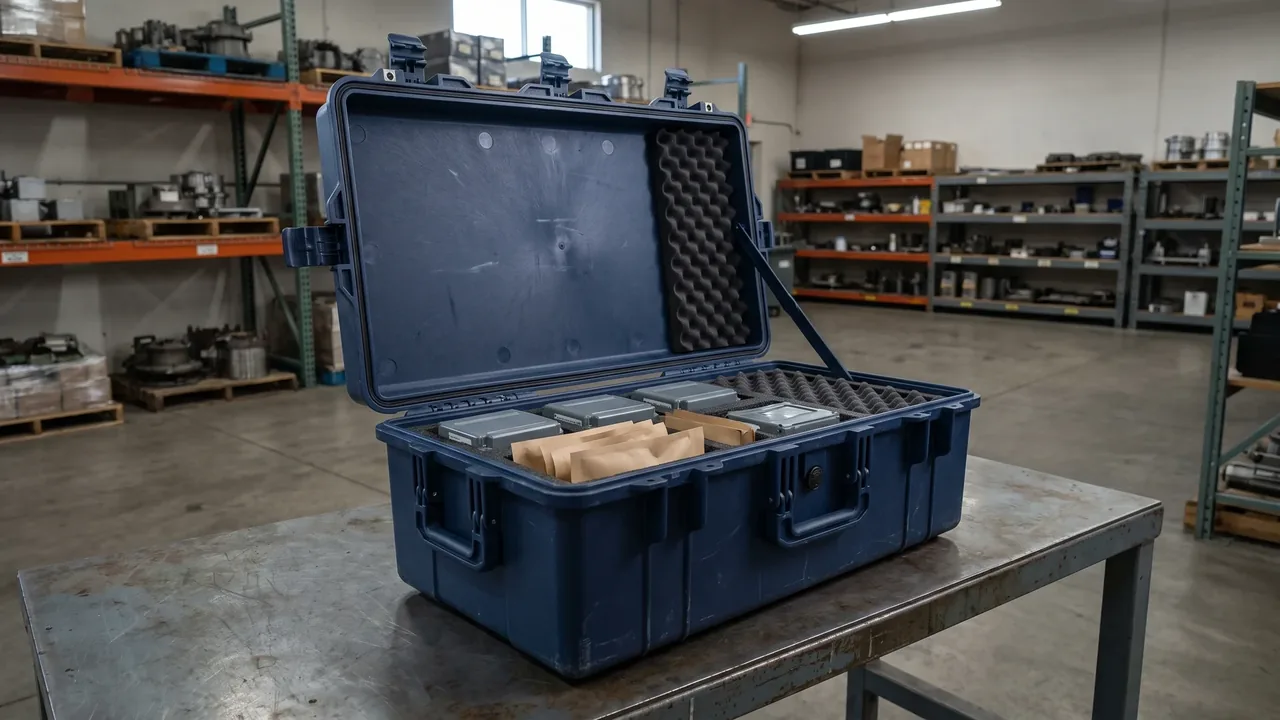
In communication base stations, radar sites, medical imaging, and industrial automation sites, electronic equipment must both prevent external electromagnetic interference from intruding and avoid leaking its own electromagnetic emission. For equipment that is sensitive or carries transmitting functions and is stored or transported in strong electromagnetic environments, the protective case electromagnetic shielding isolates internal and external electromagnetic fields through a metal shell and conductive sealing, which is the key means to maintain device performance, meet EMC regulations, and ensure signal security. This article focuses on the case itself and systematically reviews shielding principles, shielding effectiveness metrics, material and structural points, seam control, internal layout, filtering and grounding, typical environments, verification methods, and maintenance, helping engineering and procurement build practical shielded storage and transport plans and avoid electromagnetic leakage causing device failure or compliance risk.
1. Basic Concepts of Electromagnetic Shielding and EMC/EMI
Electromagnetic compatibility, EMC, means a device operates normally in its electromagnetic environment without causing unacceptable interference, covering both immunity and emission; electromagnetic interference, EMI, is the electromagnetic energy that causes interference. The "electromagnetic shielding" of a protective case uses a continuous shell made of highly conductive or highly permeable material to attenuate electromagnetic waves passing through it, protecting internal devices from external strong fields and preventing internal emission sources from leaking. Shielding targets electric fields, magnetic fields, and electromagnetic fields, with different mechanisms per frequency band: high frequencies rely mainly on reflection and absorption, while low-frequency magnetic fields depend more on high-permeability materials. Understanding this set of concepts is the prerequisite for selection: not every "metal case" is equivalently shielded; seams, holes, and grounding methods determine actual effect. Related EMI shielding case design is referenced in the EMI shielding case guide.
2. Why Protective Cases Need Electromagnetic Shielding
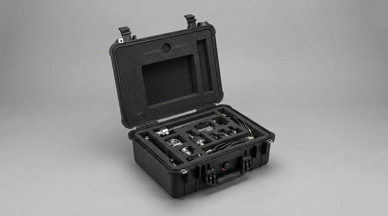
Typical objects needing shielded storage and transport fall into three categories: first, highly sensitive receiving equipment such as communication receivers and measuring instruments, where external strong fields raise noise floor or even cause saturation; second, modules with transmitting functions such as radios and radar components, which need to prevent energy leakage interfering with surroundings or revealing signals; third, equipment containing digital circuits and storage, where electromagnetic pulses or nearby strong sources may cause malfunction or data corruption. Under increasingly strict EMC regulations, the storage and transport stage is also regarded as part of the device electromagnetic environment, and a shielded case provides a "clean space" during transit, temporary storage, and before field deployment. Additionally, for confidential or easily intercepted equipment, shielding has signal security meaning. Note that shielding addresses electromagnetic field isolation, a different dimension from waterproofing and impact resistance, often requiring composite design. For communication electronics protection, the communication electronics protective case article extends the discussion.
3. Shielding Effectiveness and Common Metrics
Shielding Effectiveness, SE, is defined as the ratio of field strength at a point with and without shielding, in decibels, dB. Higher values mean stronger shielding: 20 dB attenuates field about 10 times, 40 dB about 100 times, 60 dB about 1000 times, and industry and military grades often require above 60 dB or higher. SE consists of reflection loss, absorption loss, and multiple-reflection correction, varying with frequency: absorption is significant at high frequencies, while low frequencies rely more on reflection and permeability. When selecting, require the manufacturer to provide a frequency-segmented SE curve rather than a single number, because good performance at one frequency does not mean good across all bands. Testing is mostly done in standard shielded rooms or GTEM cells. For procurement, clarifying "what SE is needed at which frequency band" is more meaningful than vaguely asking for "high shielding," and the band and threshold should be written into the technical agreement.
4. Influence of Case Material on Shielding
Shielding mainly relies on the conductive continuity of the shell. Aluminum alloy and steel cases have good conductivity and are the mainstream of shielding cases; stainless steel resists corrosion but its permeability is not necessarily optimal. To shield a plastic case, conductive paint, vacuum metal plating, or conductive fabric lining is applied to the surface, but the durability and seam treatment of such treatments are difficult. The key factor affecting shielding is whether the shell forms a continuous low-resistance path; any insulating break becomes a leakage channel. Engineering often uses a "double-shell" idea: an outer structural protection layer and an inner conductive shielding layer separated by insulation, balancing mechanical and electromagnetic needs. Material selection should also consider weight, cost, and environmental resistance. For cross needs of static and shielding, the ESD anti-static protective cases and the ESD shield case articles provide related perspectives.
5. Seams, Holes, and Shielding Integrity
The weakest points of a shielding shell are often seams and holes: lid mating gaps, latch perforations, hinge clearances, breathable valves, cable penetrations, display windows, and so on. Electromagnetic waves easily leak from millimeter-scale seams, and the length direction of a seam forms a "slot antenna" for specific frequencies. Control points: reduce unnecessary holes; metalize or use waveguide-below-cutoff structures for necessary holes; set continuous conductive gaskets on the lid mating face with sufficient compression; make conductive bridges at latch and hinge areas to avoid resistance breaks at mechanical connections; choose conductive shielded or electromagnetically sealed breathable valves. An empirical rule is that seam size should be far smaller than the working wavelength, which is especially strict in high-frequency environments. Shielding integrity is a system engineering; looking only at sheet shielding rate while ignoring seams often leads to measured SE far below expectation.
6. Application of Conductive Gaskets and Finger Stock
To maintain conductive continuity on an openable lid, conductive sealing gaskets such as conductive silicone and metal-wire braided gaskets, and finger stock, EMI gasket finger stock, are commonly used. Conductive gaskets serve both waterproof and shielding roles, relying on elasticity to maintain low-resistance contact when the lid closes; finger stock provides multi-point elastic contact, suiting frequent opening and long seams. Selection focuses on: resistivity and oxidation resistance of conductive fillers such as silver, nickel, and copper plating; compression and rebound; performance retention under humidity, heat, and salt spray; and whether it also serves as waterproof sealing. Installation must ensure the gasket is continuous with no break, well bonded to the shell, and not insulated by paint or anodizing layers. On gasket material basics, combine with the case seal material selection article to understand its dual function.
7. Internal Layout: Equipment Zoning and Cable Management
Internal layout of a shielding case also determines effect. The principle is to zone high-sensitivity circuits away from strong emission sources, using metal partitions for further isolation; cables are common leakage paths, and in-out lines must pass through filter connectors or feedthroughs, and be routed inside to avoid forming large loop antennas; if necessary, add local shield cans to modules. For cases with multiple devices, classify signals: power, radio frequency, and digital control should be routed separately and filtered and grounded nearby. If the cable jacket bonds poorly with the shell, it acts like an antenna introducing or extracting interference. The layout stage can be guided by three phrases: minimum loop area, shortest leads, good bonding. For military high-demand scenarios, the military electronics case article gives stricter layout references.
8. Filtering, Grounding, and Equipotential Bonding
For shielding to work, filtering and grounding are indispensable. Power and signal entering and leaving the shielded case should pass through filters or feedthrough capacitors to block interference conducted along wires; the case itself should establish a low-impedance grounding channel so induced current has a path rather than re-radiating at seams. Equipotential bonding requires internal metal parts, shields, and device chassis to connect to a single reference point, avoiding ground loops introducing differential-mode interference. A common practical error is "having a shield shell but leaving it floating ungrounded," where external fields still enter via capacitive coupling. Filter device selection must match frequency and current, and the cross-section and connection reliability of grounding conductors directly affect high-frequency effectiveness. For base-station equipment storage, the telecom base station case article involves typical grounding scenarios.
9. Typical EMC/EMI Environments
Typical strong electromagnetic environments include communication base stations and equipment rooms with multi-frequency transmission and adjacent-channel mutual interference, radar sites with high-power pulsed fields, medical imaging rooms with strong static magnetic fields such as MRI and radio frequency, industrial automation lines with variable-frequency drives, welding, and motor groups, and military electronic warfare and interception environments. The frequency composition and field strength levels of different environments vary greatly, and shielding schemes should "set indicators by environment." For example, radar sites focus on SE against high-frequency high-power pulses, while medical environments also need magnetic shielding materials such as permalloy for static fields. For radar equipment, the radar antenna case article provides specific references. Clarifying the environmental spectrum is the starting point for proposing reasonable shielding requirements and the source of subsequent verification criteria.
10. Relationship Between Shielding Cases and ESD
Electromagnetic shielding and anti-static, ESD, are often confused but are related yet different: shielding targets continuous electromagnetic field isolation, while ESD targets damage from instantaneous electrostatic discharge. Many sensitive electronics fear both field interference and static electricity, so shielding cases often need both functions: the inner wall is conductive with controllable grounding resistance to avoid friction charging on opening or personnel discharge hitting the device. If the device is static-sensitive, require surface resistance in the ESD safe range, and pair with anti-static packaging and wrist straps. On cross design of ESD and shielding, the ESD anti-static protective case and the aforementioned ESD shield case articles extend the discussion, helping distinguish "shielding fields" from "dissipating static."
11. Verification Methods: Shielded Room and GTEM Testing
Shielding effectiveness verification commonly uses two types: first, the standard shielded room method, placing the sample in a fully shielded room and using transmitting and receiving antennas to measure the field difference with and without the sample, obtaining an SE curve, authoritative but expensive; second, the GTEM cell, gigahertz transverse electromagnetic cell, small in size and fast, suiting R&D and production sampling. Testing must cover the target frequency band and be conducted in the real state of lid closed with typical cable penetration, because open lid or unsealed holes severely distort results. Criteria should state the frequency band and minimum SE threshold. Incoming sampling can combine these two methods, doing full-band scans on critical cases. At the compliance level, shielding performance can also be part of EMC pre-compliance testing, finding leakage points early then iterating structure.
12. Selection Points and Common Misunderstandings
Selection points: first define the frequency band and required SE threshold and write into the agreement; confirm the shell is a continuous conductive path, prioritizing metal or qualified conductive treatment; check shielding measures for seams, holes, breathable valves, and cable penetrations; require frequency-segmented SE curves rather than a single number; confirm whether waterproof and ESD are also needed; evaluate opening life and gasket replacement. Common misunderstandings: treating "metal case" directly as "shielding case" while ignoring seams and grounding; asking only total SE without specifying frequency band; using ordinary valves or non-conductive gaskets that break shielding; having a shield shell but no grounding; ignoring cable penetration as the largest leakage source. The avoidance method is to treat shielding as an integrated engineering of "continuous conductive shell plus controlled seams plus reasonable grounding" rather than looking only at material. On industry trends and composite functions, the protective case industry trends article is a reference.
13. Maintenance, Inspection, and Life Assessment
Shielding performance degrades with gasket aging, coating wear, and bonding loosening. Maintenance recommends regularly checking whether conductive gaskets and finger stock are broken, oxidized, or lose elasticity; cleaning mating faces to avoid insulating dirt; checking grounding wires and bridges for firmness; avoiding scratches on conductive coating cases, and promptly repairing local damage while ensuring conduction with the body. Life assessment can combine opening counts, environment severity, and periodic SE sampling, setting mandatory replacement thresholds for critical-duty cases. Build a one-case-one-file record of each gasket replacement and test result. On overall case repair and spares, the case repair and spare parts article helps incorporate shielding parts into unified upkeep, preventing performance from silently deteriorating.
14. Shielding Case Implementation and Supplier Capability
Turning electromagnetic shielding from a spec into a usable product depends on the supplier's process and testing capability. Prioritize manufacturers with conductive gasket die-cutting, conductive coating or metallization, and shielded-room or GTEM testing ability, who can give an SE curve by frequency band rather than a single number and guarantee conductive continuity at openable locations. For critical batches, require a frequency-segmented shielding effectiveness test report covering the real state of lid closed with cable penetration, with test setup photos. The EMI shielding case guide details design points.
Custom needs often include double-shell structure, local shield cans, filter connectors, and equipotential grounding terminals, and the supplier should output structural drawings, material certificates, and a closed test loop. At delivery, build a one-case-one-file record of each gasket replacement and SE sampling for life assessment. For first cooperation, validate with a small batch then full inspection, writing frequency-segmented SE and sampling ratio into the contract. Combined with the ESD shield case and the ESD anti-static protective cases references, you can turn shielding requirements into an acceptable evidence chain and avoid mistaking a metal case for a shielding case.
15. Composite Design of Shielding with Waterproofing and Impact
Strong electromagnetic environments often simultaneously require waterproofing and impact resistance, so shielding cases need composite design rather than single-dimension optimization. In implementation, use the dual role of metal shell serving both shielding and structure, and conductive gasket serving both shielding and waterproofing, to reduce part conflicts; for positions that must have windows or ventilation, use conductive shielded valves or waveguide structures that preserve shielding while allowing airflow. For impact, the metal shell itself has good rigidity, but edges should be radiused or corner-guarded to avoid impact cracking that breaks conductive continuity. The communication electronics protective case and the military electronics case articles show composite duty examples.
Note that composite design increases seams and bonding points, which instead become shielding weak spots, so every mating face should have conductive bonding and compression. For cases with electronic modules, shielding, EMC, RoHS, and waterproofing must be evaluated together to avoid neglecting one for another. When selecting, list SE frequency threshold, IP grade, IK grade, and ESD as a composite indicator checklist with evidence per item. Only then can storage and transport in complex EMC and EMI sites isolate signals while withstanding environment and handling. The telecom base station case and the radar antenna case articles give typical field scenarios.
As a supplement, the continuous effectiveness of a shielding case also relies on dynamic monitoring of leakage paths: beyond seams and holes, conductive gasket wear from frequent opening, coating scratches, and loose grounding terminals are all sources of performance decay, so periodic SE sampling on critical cases should cover these areas. For complex configurations with multiple modules and cables, build a mapping table of which cable route corresponds to which frequency band filter, to avoid blind rework during rectification. At the same time, the composite requirements of shielding, ESD, and waterproofing evolve with equipment upgrades, so the design end should retain extensible shielding and grounding interfaces. The esd shield case article gives more on static control.
On the user side, include the shielding case in an electromagnetic environment ledger: record the spectrum characteristics of the use site, SE sampling values, and maintenance actions, so that long-term accumulation identifies performance inflection points. For confidential or highly sensitive equipment, combine physical isolation and access control so that shielding upgrades from a case metric to a link in the storage and transport security system. Managing design, verification, maintenance, and use in a closed loop is what lets electromagnetic shielding work stably in complex EMC and EMI sites. The military electronics case and the radar antenna case articles show typical high-demand scenarios where this discipline pays off.
Finally, during maintenance never cover the conductive bonding face with ordinary paint or insulating coating, because that creates a new leakage point out of nowhere and wastes the carefully designed shielding. Train operators to handle the case by its shell, keep gaskets clean, and report any deformation of the mating face immediately. With these habits plus periodic full-band SE checks, the shielding rating remains a managed reality rather than a specification that silently degrades, protecting both the equipment and the mission it supports.
FAQ
Q: Does a metal case equal an electromagnetic shielding case? A: No. Shielding effectiveness depends on whether the shell forms a continuous low-resistance conductive path, not merely "whether it is metal." Even an all-metal case, if the lid mating gap, latch perforations, hinge clearances, breathable valve, and cable penetrations have untreated breaks, electromagnetic waves leak from these seams and the measured shielding effectiveness may be far below expectation. A truly qualified shielding case uses conductive gaskets or finger stock at openable locations to maintain continuous contact, metalizes or uses waveguide-below-cutoff structures for necessary holes, and grounds the case reliably. Therefore when selecting, do not look only at the words "metal shell," but examine seam control, conductive continuity, and grounding design, and preferably require the manufacturer to provide a frequency-segmented shielding effectiveness curve as evidence. When reviewing that curve, check the test setup notes as carefully as the numbers, because a curve measured without cables or with the lid only loosely closed flatters the design. Ask which apertures were open during the test and whether the case was grounded in the chamber. A supplier who answers these questions readily usually runs a disciplined process. A site visit to watch one test being run tells you more than three documents, and reputable factories welcome it. Keep the answers in the project file for the acceptance review. Also confirm who pays for a re-test after any design change.
Q: What does 60 dB shielding effectiveness mean, and is higher always better? A: Shielding effectiveness is expressed in decibels as the ratio of field strength with and without shielding. 60 dB means field attenuation about 1000 times, and industry and military grades often require above 60 dB, with some stringent scenarios higher. But "higher is better" depends on need and cost: higher SE needs better materials, denser conductive gaskets, stricter seam control and grounding, raising cost and weight, and some low-frequency magnetic fields need special high-permeability materials to be effective. The pragmatic approach is to clarify the frequency band and field strength of the equipment environment first, then set the necessary threshold, for example targeting a specific communication band rather than blindly pursuing high full-band indicators. Writing the band and minimum SE into the technical agreement is more meaningful than vaguely asking for "high shielding." Record the environment survey that justified the threshold, since auditors and customers often ask why that number was chosen. When several devices share one case, adopt the strictest device requirement and note the others, so a future equipment change does not silently invalidate the protection basis. Keep the survey spectrum as an attachment to the agreement. Budget reviewers respond better to a band table than to a single headline figure. Note that shielding at low frequencies often drives the whole material choice. Revisit the threshold when the site adds new transmitters.
Q: Will the case seams and breathable valve ruin the shielding? A: Yes, seams and breathable valves are exactly the most common leakage points of a shielding shell. Electromagnetic waves easily escape from millimeter-scale seams, and a long seam acts like a "slot antenna" efficiently radiating at specific frequencies; an ordinary breathable valve without conductive shielding structure also becomes a hole leakage. Control means include using continuous conductive gaskets on the lid mating face with sufficient compression, making conductive bridges at latch and hinge areas, switching necessary ventilation to conductive shielded valves or electromagnetic sealing, and minimizing or metalizing all holes by wavelength scale. The empirical rule is that seam size should be far smaller than the working wavelength, especially strict in high-frequency environments. So evaluating a shielding case must include seams, breathable valves, and cable penetrations; looking only at sheet shielding rate severely misjudges. Inspect the valve and seams with the same seriousness as the panels, because a single unshielded valve can undo an otherwise excellent shell. During acceptance, a spray test plus a quick visual check of gasket compression finds most assembly faults before shipment, and costs far less than a laboratory dispute later. A torque or compression checklist at the latch keeps the assembly consistent across shifts. Painted flanges must be masked before gasket fitting or contact fails.
Q: What should I watch for cables entering and leaving the shielding case? A: Cables are among the largest leakage sources of a shielding case, and poor handling voids the whole shielding. The principle is that in-out lines must pass through filter connectors, feedthroughs, or filter capacitors to block interference conducted along wires, never directly threading ordinary cables through holes. Internal routing should be classified: power, radio frequency, and digital control routed separately to avoid forming large loop antennas; the cable jacket should bond well with the shell, otherwise it acts like an antenna introducing or extracting interference. For multi-device cases, add local shield cans to modules and filter and ground nearby. Remember three phrases in layout: minimum loop area, shortest leads, good bonding. These details determine actual shielding effectiveness and should be included at the design stage rather than remedied later. Draw the cable schedule before the case layout is frozen, because every late connector change forces a new penetration and a new leak risk. Label each feedthrough with its filter type and frequency coverage, and keep that list with the case file so field crews never substitute an unfiltered connector in an emergency. One spare filtered connector per case type belongs in the field kit. Route sensitive cables away from power runs even inside the case. Update the schedule whenever firmware or modules change.
Q: Does a shielding case need grounding, and what if it is not grounded? A: Yes, it needs grounding. For the shielding shell to work, a low-impedance grounding channel is usually established so induced current has a path rather than re-radiating at seams. A common error is "having a shield shell but leaving it floating ungrounded," where external electromagnetic fields still enter the case via capacitive coupling, greatly reducing shielding effectiveness. The correct approach connects the case, internal metal parts, and device chassis to a single reference point for equipotential bonding, avoiding ground loops introducing differential-mode interference; power and signal in-out block conducted interference through filters. The cross-section and connection reliability of grounding conductors directly affect high-frequency effectiveness, so grounding is not an optional accessory but an inseparable part of the shielding system, and the specification and connection method of grounding terminals should be confirmed when selecting. For mobile deployments, specify a quick clamp terminal and include the ground resistance value in the annual inspection, since a corroded earth point quietly erodes the measured SE long before anyone notices. Photograph the grounding arrangement at each site so repeated deployments restore the same configuration rather than an improvised one. Copper strap resists corrosion better than braided wire in coastal air. Ground lugs should be crimped, not twisted, for repeatable contact. Document the earth point location on the site map.
Q: Are electromagnetic shielding and anti-static the same thing? A: No, they are different but often need to coexist. Electromagnetic shielding targets continuous electromagnetic field isolation, preventing external interference from entering or internal emission from leaking; anti-static, ESD, targets damage from instantaneous electrostatic discharge to devices. Many sensitive electronics fear both field interference and static electricity, so shielding cases often need both functions: the inner wall is conductive with controllable grounding resistance to avoid friction charging on opening or personnel discharge hitting the device. If the device is static-sensitive, require surface resistance in the ESD safe range, and pair with anti-static packaging and wrist straps. When selecting, distinguish "shielding fields" from "dissipating static," and specify indicators separately if necessary, avoiding using shielding performance to cover an ESD protection gap that damages devices during opening. Keep the two test reports separate in the acceptance file, because an auditor looking for ESD evidence should not have to infer it from a shielding curve. Train operators to wear the wrist strap even when the case is grounded, since human contact remains the most frequent discharge path in daily handling. Review the wrist strap log weekly in EPA areas. Ionizers help where wrist straps hinder movement.
Q: How is shielding effectiveness verified, and how to sample on arrival? A: Two common methods are used: the standard shielded room method places the sample in a fully shielded room and uses transmitting and receiving antennas to measure the field difference with and without the sample to obtain an SE curve, authoritative but expensive; the GTEM cell is small and fast, suiting R&D and production sampling. Testing must cover the target frequency band and be conducted in the real state of lid closed with typical cable penetration, otherwise open lid or unsealed holes severely distort results. Incoming sampling recommends full-band scans on critical cases, with criteria stating the frequency band and minimum SE threshold. Shielding performance can also be part of EMC pre-compliance testing, finding leakage points early then iterating structure. Writing "frequency-segmented SE curve" and sampling ratio into the agreement turns the manufacturer's claim into a verifiable evidence chain. Note the cable configuration and lid state in every sampling record, because comparing a sealed case today with a penetrated case last quarter explains more disputes than any single number. For critical programs, repeat the scan after the first year of service to establish a degradation baseline for the fleet. Keep one case as a reference unit that never ships, giving every future scan a stable comparison. Photograph the setup each time for the archive. A clear record makes disputes short.
Q: Does a shielding case degrade over time, and how to maintain it? A: Yes, it degrades. Shielding performance gradually deteriorates with conductive gasket aging, coating wear, and bonding loosening. Maintenance recommends regularly checking whether conductive gaskets and finger stock are broken, oxidized, or lose elasticity; cleaning mating faces to avoid insulating dirt accumulation; checking grounding wires and bridges for firmness; avoiding scratches on conductive coating cases, and promptly repairing local damage while ensuring conduction with the body. Life assessment can combine opening counts, environment severity, and periodic SE sampling, setting mandatory replacement thresholds for critical-duty cases. Build a one-case-one-file record of each gasket replacement and test result. Incorporating shielding parts into a unified repair and spare system prevents performance from silently deteriorating and ensures long-term electromagnetic safety in storage and transport. Store spare gaskets in their original packaging and date them, because an aged spare fits poorly even when it looks new. When a batch shows falling SE at the same seam, inspect the tooling or assembly jig rather than blaming the operators, since repeatable faults usually trace to a process drift. Archive the tool version with each batch record for this reason. A short annual refresher keeps inspection criteria alive. Rotate stock so older gaskets get used first.