

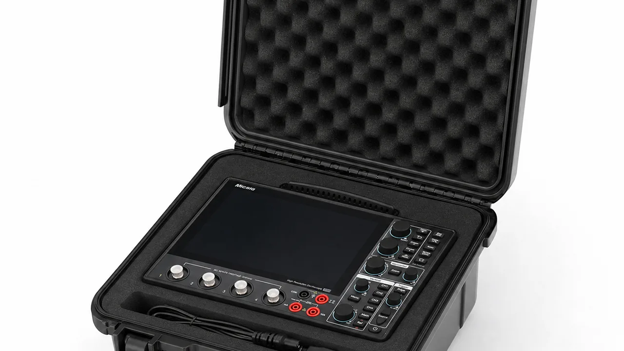
The logistics chain behind a base station is longer than most people expect. Equipment leaves the factory, passes through regional and city depots, sits in a contractor store, travels by pickup truck to site, and is finally hoisted up a tower to a platform tens of metres above ground. Along that chain, remote radio units take handling impacts, optical modules face thermal cycling and electrostatic discharge, and jumpers and pigtails face bending and crushing. Site acceptance usually only checks whether the cell will power up, so early failures are rarely traced back to inadequate transport protection.
The JUNZHIJIA position on base station equipment cases is that the mechanical sensitivity of the RF chain, the bend sensitivity of the optical chain and the electrostatic sensitivity of electronics must be handled by three different liner structures, not by one generic foam. Sealing an RRU, a BBU, optical modules and jumpers into a single box over a single layer of foam stacks three failure modes onto one weak point.
Table of Contents
- Real Risks Across the Base Station Logistics Chain
- Fixing and Vibration Damping for RF Modules
- Cavity Packaging for Baseband Units and Cabinet Assemblies
- Antenna Modules and Feeder Assemblies
- RF Connectors and Jumpers: Torque, Dust and Plating
- Optical Modules and Pigtails: Bend Radius and End Face Cleaning
- ESD Control and Conductive Liner Options
- Tower Climb Logistics: Weight, Lift Points and One-Person Carry
- IP Rating Requirements Before Installation and Arrival Criteria
- Water Ingress During Site Storage
- Depot Stacking and Palletised Transport
- Shell Material and Liner Comparison for RF-Sensitive Loads
- Frequently Asked Questions FAQ
- Conclusion and Related Reading
Real Risks Across the Base Station Logistics Chain
Base station equipment falls into three groups with entirely different protection needs. The first is RF power equipment, including remote radio units, active antenna units and combiner units, weighing fifteen to forty-five kilograms each. These contain power amplifiers, filters and heatsink fins, and they are sensitive to drop impact and sustained vibration, because fins deform under compression and distort the airflow path. The second is baseband and transmission equipment, including baseband processing units, transmission gear and power modules. These are built around printed circuit boards and connectors, and are sensitive to electrostatic discharge, humidity and connector wear from repeated mating. The third group covers optical and RF interconnect items such as optical modules, pigtails, jumpers and feeder assemblies. These are not always the most expensive, but they cause the greatest commissioning delay on site.
The risks map cleanly onto the logistics stages. Factory loading threatens stacking pressure and pallet drops. The regional depot threatens long term damp heat and dust. The contractor store threatens repeated handling damage and mixed-load crushing. Road transport threatens vibration and longitudinal shock under braking. Site storage threatens rain, condensation and temporary placement on wet ground. Tower hoisting threatens sling compression and swinging impact.
| Equipment group | Loading | Storage | Road transport | Site storage | Tower hoist |
|---|---|---|---|---|---|
| --- | --- | --- | --- | --- | --- |
| RF power equipment | Impact, stacking | Moisture, dust | Vibration, shift | Rain, condensation | Sling compression, swing |
| Baseband and transmission | Drop | Damp heat, stacking | Vibration, mating | Water, condensation | Normally not hoisted |
| Optical and RF interconnect | Crush, bend | ESD, dust | Bend, vibration | Damp, contamination | Bend, end face dirt |
Treating this matrix as a design input explains why one box type is not enough. The value of a protective case is not that everything fits, but that each specific failure path is cut separately.
Fixing and Vibration Damping for RF Modules
Remote radio units and active antenna units are the heaviest single items in base station logistics and carry the highest risk of shifting in transit. Most use cast aluminium housings with heatsink fins, mounting ears on the base or sides, and sometimes lifting holes at the corners. The first task of the fixing design is to constrain movement in six degrees of freedom rather than simply filling the box with foam. The correct approach is a rigid support plate under the main load bearing face of the unit, so the plate carries vertical load; eight to twelve millimetres of clearance between the fins and the case wall, filled with soft EVA or IXPE; and clip retained limit blocks against the mounting ears to stop fore and aft movement.
Damping has to separate shock from vibration. Shock comes from handling drops, is short in duration and high in amplitude, and is absorbed by compression of the foam, so thickness and compression curve decide the result. Vibration comes from road transport, is long in duration and low in amplitude, and is dissipated by the damping behaviour of the foam, where the key issue is avoiding resonance with the equipment. Most EVA foams have a natural frequency between ten and thirty hertz, close to the dominant frequency band of truck transport. A double layer is therefore recommended: five to eight millimetres of high density EVA as a damping layer, then twenty to thirty millimetres of medium density EVA as an energy absorbing layer, moving the resonance out of the main excitation band. See Drop Test Height by Weight for test height classes and acceptance logic.
Limit blocks should use high density EVA of sixty-five to seventy-five Shore A, or injection moulded PP with a rubber overmould, so they can carry side load without scratching the cast aluminium surface. Every liner in direct contact with the equipment should be a closed cell material, because an open cell foam absorbs moisture and becomes a corrosion source in damp conditions. On finned faces, never press foam directly onto the fin tips. The tips are thin wall structures, and sustained pressure bends them permanently, which degrades the cooling performance of the power devices.
Cavity Packaging for Baseband Units and Cabinet Assemblies
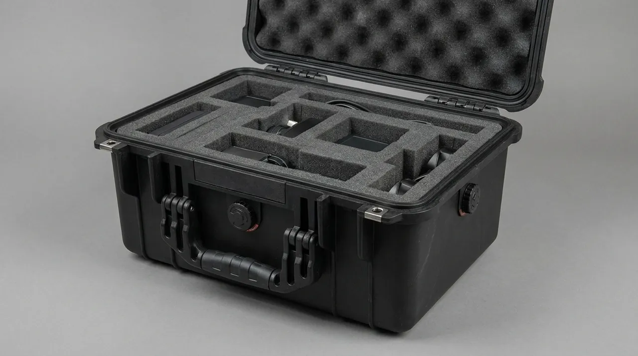
Baseband processing units and transmission equipment usually follow a nineteen inch rack format, two to four units high, weighing ten to twenty-five kilograms. Their typical failure is not a broken shell but cracked solder joints, dislodged connectors or loosened heatsinks inside the chassis. These defects may not appear during a power-on test, and instead surface months later as intermittent faults. The packaging objective is therefore to shorten the path by which shock acceleration reaches the chassis, and to prevent the main board from bending.
The recommended arrangement is a three point support: two side rails plus a base support strip. EVA side rails cut to match the rack ears transfer equipment weight into the reinforcement ribs of the case wall. Two support strips run along the length of the unit underneath, at least thirty millimetres wide, positioned under the structural beams of the chassis rather than the circuit board area. The top provides location only, not clamping, with a closing force under fifty newtons so that the lid does not load the top cover. Where units must be stacked, place a three millimetre PP divider between layers and land the divider on the case side walls to create an independent load path.
The panel and interface area is another weak point. Optical ports, electrical ports, debug ports and reset buttons are easily damaged by stacking or compression, so at least twenty-five millimetres of clearance should be kept between the panel side and the case wall, filled with low density PE foam. Interface protection caps should be fitted before packing and dust caps must not be missing. For equipment that is repeatedly mated on site, a fabric or PP accessory compartment can hold patch cords, debug cables, screws and mounting brackets separately, so that metal accessories cannot slide and strike the equipment shell in transit. See Case Internal Foam Types for liner material selection.
Antenna Modules and Feeder Assemblies
Antennas are large in area, thin in section and irregular in shape. The radome is usually fibreglass or ASA, which is weaker in impact than a metal housing, and a cracked or crazed surface lets rain penetrate and degrades the voltage standing wave ratio. Feeder assemblies include jumper cables, main feeders and earth leads, ranging from one metre to more than ten metres. Flexible jumpers can be coiled, while semi-flexible or rigid feeders must not be bent below their specified radius.
Antenna fixing should follow the rule of face support, edge location and no load on the radome face. Face support means the entire back of the radome rests on an EVA plate matched to its contour, so external force spreads across the plane instead of concentrating at a few points. Edge location means limit strips on all four sides constrain horizontal movement. No load on the radome face means the antenna must never be placed radome down; the metal back plate or mounting bracket must contact the support plate. Adjustable brackets should be removed and packed separately so they cannot scratch the radome inside the case.
Feeder storage should introduce controlled bend radius. Jumpers can be coiled to a diameter of at least three hundred millimetres and secured with soft ties at three or four points, never with metal cable ties. The minimum bend radius of a semi-flexible feeder is generally ten times its outer diameter for a single bend and twenty times for repeated bending. Beyond that limit, the relative position of the inner conductor and the outer shield changes, producing impedance discontinuities and higher insertion loss. Feeder connectors inside the case should face upward or lie horizontally so the connector never becomes a load bearing point. Where an antenna and its feeder share a case, fit a PP divider between them to stop the antenna metalwork striking the connector. For assemblies stored on site for long periods, the case should resist ultraviolet exposure and rain so the components are not left exposed during the waiting period.
RF Connectors and Jumpers: Torque, Dust and Plating
RF connectors are the most delicate and most easily damaged parts in a base station link. Common types include type N, 7/16 DIN and 4.3-10. Recommended tightening torque is roughly twenty-five to thirty newton metres for 7/16 DIN, about five newton metres for 4.3-10 and one point five to two newton metres for type N. Insufficient torque raises contact resistance and generates passive intermodulation, while excessive torque deforms threads and dielectric supports. Transport does not involve tightening, but the connector must arrive free of load, contamination and deformation, otherwise the first installation on site will fail.
Dust control is the first priority. Dust and metal particles on the inner conductor significantly worsen passive intermodulation performance, so factory packing must cover the inner conductor completely with a protective cap that forms a reliable seal against the connector body. Where a connector requires an airtight interface, the cap should itself provide a defined sealing level. When several connectors travel in one case, they must not touch each other or be strung on a single cable tie; each needs its own cradle.
Plating protection also matters. Tri-metal and silver plated finishes form silver sulphide in sulphur bearing atmospheres, raising contact resistance, and silver plating corrodes in chlorine bearing environments. For jumper assemblies used at coastal or industrial sites, fit desiccant inside the case, keep humidity low, and avoid sulphur cured nitrile rubber in direct contact with the finish. Cross linked polyethylene or EVA is preferable, and where a rubber limit block is unavoidable, specify a low sulphur compound validated by accelerated ageing. Count protective caps back in at the end of transport so that none is left on site as foreign object debris.
Optical Modules and Pigtails: Bend Radius and End Face Cleaning
Optical links tolerate mechanical stress very poorly. Bending below the minimum radius produces macrobend loss, and long term small radius storage leads to stress corrosion and fibre breakage. The usual industry rule is a minimum bend radius of ten times the cable outer diameter in the static state and twenty times during dynamic installation. Bend insensitive fibre may be rated down to seven point five millimetres at specific wavelengths, but that is a limit value rather than a design value. Pigtails and patch cords must be constrained by a purpose designed arc channel or reel inside the case.
The table below gives suggested minimum bend radii for common cables in the transport and storage state. Values are engineering guidance and the cable manufacturer data sheet always takes precedence.
| Cable type | Example outer diameter | Suggested static radius | Suggested dynamic radius |
|---|---|---|---|
| --- | --- | --- | --- |
| Single fibre pigtail | 0.9 mm | 15 mm | 30 mm |
| Duplex patch cord | 2.0 mm | 25 mm | 50 mm |
| Duplex patch cord | 3.0 mm | 30 mm | 60 mm |
| Indoor multi fibre cable | 6.0 mm | 60 mm | 120 mm |
| Outdoor armoured cable | 10 mm | 150 mm | 200 mm |
End face cleanliness is the second key point. Even micron level dust or oil on a fibre end face raises insertion loss and degrades return loss, and at high power density it can burn the end face. Transport protection therefore means keeping the end face protected at all times. Every patch cord needs dust caps at both ends forming a seal against the ferrule, and the case should carry lint free wipes or a dedicated cleaning pen stored away from the equipment itself so that lint and dust do not enter the connector area at the moment of opening.
The optical module itself needs protection from static, moisture and impact. An optical module is a precision optoelectronic assembly, and electrostatic discharge can degrade the laser, showing up as a slow fall in output power that is very hard to detect in early testing. Use antistatic bags or antistatic foam inside the case and require wrist straps for operators. Where modules travel with equipment, place them on a separate antistatic tray and keep them away from direct contact with metal structures. In cold transport conditions, avoid rapid temperature change at high humidity so that condensation does not form internally.

ESD Control and Conductive Liner Options
Electrostatic discharge damages telecom equipment in a hidden way. A single human body discharge may only shift device parameters slightly, so a functional test still passes, and the problem appears only after months of service as a rising bit error rate or degraded RF performance. Classifying liners as insulating, static dissipative or conductive, and selecting the right class, is therefore the lowest cost and most effective single measure in case design.
Insulating materials have a surface resistance above ten to the twelfth ohms. Ordinary EVA, PE foam and polypropylene sheet fall into this class, and they suit power supply housings and structural parts with low static sensitivity. Static dissipative materials sit between ten to the sixth and ten to the ninth ohms, allowing accumulated charge to drain at a controlled rate without a fast discharge, and they suit trays that carry circuit boards and optical modules directly. Conductive materials are below ten to the sixth ohms, used where shielding is needed or as part of a grounding path, but direct contact with exposed circuit nodes can itself cause discharge damage.
| Liner option | Surface resistance | Suitable parts | Caution |
|---|---|---|---|
| --- | --- | --- | --- |
| Standard EVA foam | Above 10^12 ohm | Metal structures, power shells | Not against bare boards |
| Antistatic EVA | 10^6 to 10^9 ohm | Baseband units, optical trays | Verify resistance consistency |
| Conductive PE foam | Below 10^6 ohm | Modules needing shielding | Avoid contact with solder joints |
| Antistatic IXPE | 10^6 to 10^9 ohm | Thin devices, panels | Closed cell, low moisture uptake |
| Conductive fabric on board | Depends on fabric | Trim and shield layers | Requires grounding design |
Real projects normally use a combination. The case body uses standard EVA for load bearing, the tray in direct contact with equipment uses antistatic EVA, optical modules use an antistatic bag plus an antistatic tray, and structural parts use standard foam. Electrical continuity between liner sections should be provided, bonding the dissipative layer to a case earth terminal through metal rivets or conductive tape so that charge cannot accumulate locally. Verify antistatic performance by sampling surface resistance at incoming inspection and recording the numbers, rather than relying on a supplier declaration alone. Assembly area ESD requirements should follow ANSI/ESD S20.20, of which the case is only one part.
Tower Climb Logistics: Weight, Lift Points and One-Person Carry
Tower work is one of the most hazardous stages of base station construction, and case design has to serve real hoisting and climbing conditions rather than warehouse convenience alone. The practical industry limit for one-person carry is about twenty-five kilograms. Above that, the load must be split, trolleyed or raised with a winch. On a ladder at least one hand must stay on the rungs, so the case needs a shoulder or sling configuration, or must be raised separately on a line.
Lift points need defined load paths and clear marking. Metal lifting eyes or reinforced lifting holes should be provided at the four corners, with a rated load per point of at least four times the fully loaded case weight. The connection must use metal inserts to spread the load, never relying on plastic wall thickness. Corner protectors should be fitted where the sling contacts the case so the rope cannot cut the case edge during swinging. The lid to body connection must withstand the inertial load of hoisting, so that a handle failure cannot separate lid from body and drop the equipment.
Keep the centre of gravity low. Heavy items go at the bottom of the case and light items on top, and the loaded centre of gravity should stay within forty percent of the case height. Handle positions should project close to the vertical line through the centre of gravity, within about thirty millimetres, otherwise a single hand carry produces a strong tipping moment. For cases hoisted up a tower, reinforce the base and fit impact absorbing strips so that the case cannot be damaged against the steel angle members while swinging inside the tower. See Case Handle Ergonomic Design for grip parameters.
IP Rating Requirements Before Installation and Arrival Criteria
Base station equipment must retain its factory protection state until installation, and this is often overlooked on site. Remote radio units and active antenna units commonly carry IP65 to IP67 protection, which depends on three elements working together: the housing gasket, the breather valve and the interface protection caps. A cap lost in transit, or a cover not correctly reseated after an inspection, removes that protection well before the rainy season arrives. Arrival criteria should therefore place protection integrity on the same level as cosmetic condition.
The criteria fall into four groups. The first covers appearance and structure: no cracks in the housing, no bent heatsink fins, no deformed mounting ears, no stretched lifting holes. The second covers protection hardware: all interface caps present, breather valve clear, gasket not protruding or displaced, earth terminal free of corrosion. The third covers optical and RF interface cleanliness: no visible dust or oil on the inner conductor, no scratches on fibre end faces, dust caps in place. The fourth covers documentation completeness: factory test report, optical module wavelength and power labels, jumper length and type labels, and the screw and bracket packing list.
Inspection should be recorded with photographs, especially for missing caps and deformed gaskets, which require supplier confirmation before the equipment is reinstated. Where equipment has been opened for inspection, replace single use seals before closing and fit fresh desiccant. If the housing is damaged on arrival or shows signs of water at an interface, do not power it up on site; carry out an insulation and visual assessment first and decide whether to return it for repair.
Water Ingress During Site Storage
Equipment often cannot be installed immediately on arrival. Tower work, power connection or approval may delay installation by weeks or months. This waiting period is when protection is most often relaxed: the case is left in a corner of the shelter, on an outdoor platform, or directly on the ground. Daytime sun and night time cooling drive repeated temperature and humidity cycles, and the risk of water ingress and condensation rises.
Ingress follows three main paths. The first is ground water entering through capillary gaps at the case base, particularly once the base has been worn. The second is rain collecting in the recess between lid and body and seeping along the sealing face, which is most likely when the case lies flat with the seal facing upward. The third is human: opening the case in the rain, touching the sealing face with wet gloves, or closing it without drying. Countermeasures are straightforward. During storage, place the case on a pallet or timber bearers at least one hundred millimetres off the ground. Keep it upright or with the seal facing sideways where possible. Open it only under cover and wipe the sealing face dry before closing.
Condensation control follows the same logic as inside the case itself, but depends more on site discipline. Place a humidity indicator card and replaceable desiccant inside, and set a rule that the card is changed when the colour shifts. For long term storage, fit a breather valve with an ePTFE membrane so that the daily pressure differential is equalised and the gasket is not repeatedly compressed and sucked. Where indoor storage is available, keep cases ventilated rather than pressed against a wall or covered with other goods. Never place an unopened case beside a cable trench cover or under air conditioning condensate discharge.
Depot Stacking and Palletised Transport
Storage density is high in regional and city depots, so stacking is unavoidable. Under stacking the case sees long term static load, and the failure mode is creep rather than instant fracture. The wall deforms slowly under sustained pressure, the lid sealing face gradually loses flatness, and after months the deformation does not fully recover even when the load is removed. Stacking design must therefore be based on long term static load, not instantaneous strength.
The normal stacking test applies three times the fully loaded weight of a single case at forty degrees Celsius for seventy two hours, then measures residual deformation of case height and sealing face flatness after unloading. The lid top should have locating recesses matching the base profile, so an upper case cannot slide sideways off a misaligned stack. Where case weights differ, put heavier cases at the bottom in a heavy-below-light order, and limit total stack height to three layers or two point five metres. See Stacking Load Test for Cases for methods and acceptance criteria.
Palletising significantly reduces the number of handling operations and lets the depot use forklifts. A standard twelve hundred by eight hundred millimetre pallet is recommended, with cases aligned neatly and secured by two cross straps, routed clear of lid latches and breather valves. Keep the total pallet height under eighteen hundred millimetres and the centre of gravity within one third of the pallet height. Forklift operators must not push the forks into the side of a case, especially the sealing face side. For bulk equipment travelling long distances by road, add anti-slip matting between pallet and vehicle floor and provide longitudinal restraint against the whole stack so that braking cannot shift it.
Shell Material and Liner Comparison for RF-Sensitive Loads
A base station case has to balance impact resistance, static control, weather resistance and weight, and the combination of shell material and liner material determines the final result. On the shell side, rotomoulded HDPE offers the best toughness and impact performance and suits heavy RF modules handled frequently. Injection moulded PP offers better rigidity and dimensional accuracy and suits baseband packaging with internal rails and brackets. ABS and PC alloy gives a high quality surface and suits matched equipment sets that need printed identification. On the liner side, EVA suits precision cutting and load bearing, IXPE suits thin section location, PE foam suits cavity filling, and antistatic grades of EVA and IXPE suit circuit boards and optical modules.
The table below compares five typical combinations for base station loads, rated excellent, good or moderate. The values summarise engineering experience, and selection should always account for actual weight, transport mode and site environment.
| Combination | Impact | Static control | Weathering | Dead weight | Suitable load |
|---|---|---|---|---|---|
| --- | --- | --- | --- | --- | --- |
| Rotomoulded HDPE with standard EVA | Excellent | Moderate | Excellent | Heavier | Remote radio units, combiners |
| Rotomoulded HDPE with antistatic EVA | Excellent | Excellent | Excellent | Heavier | Mixed RF and baseband loads |
| Injection PP with EVA and PP divider | Good | Good | Moderate | Medium | Baseband units, transmission gear |
| Injection PP with antistatic IXPE | Good | Excellent | Moderate | Light | Optical modules, pigtails, jumpers |
| ABS and PC with antistatic tray | Moderate | Excellent | Moderate | Light | Spare kits, maintenance tool sets |
One point deserves emphasis: antistatic protection is not achieved by making the whole case conductive. A conductive liner in direct contact with a bare circuit board can itself become a discharge path. The correct approach is to let the dissipative layer carry the load, and to bond the equipment and the case earth terminal with a lead or conductive fabric so that charge drains along a controlled route. Liner weathering is also overlooked. Standard EVA embrittles under long ultraviolet exposure, so where a case is handled outdoors for years the liner should be closed cell IXPE or be protected by an ultraviolet resistant sleeve. For volume projects, validate drop, vibration and static dissipation together on the sample case before freezing the final combination.
Frequently Asked Questions FAQ
Q: Why can a remote radio unit not simply be packed tight with foam?
A: Packing tight looks like it stops movement, but in practice it converts point loads into face loads and causes secondary damage. Remote radio units are usually cast aluminium with heatsink fins, and the fin tips are thin wall structures. Foam pressing directly on the fin tips bends them permanently, which changes the airflow cross section and reduces cooling capacity. Compressed foam also transmits shock acceleration more directly into the housing instead of absorbing it. The correct approach is a rigid support plate carrying vertical load, high density limit blocks against the mounting ears for lateral restraint, and eight to twelve millimetres of clearance between fins and case wall filled with soft EVA. Foam filling also ignores resonance. Ordinary EVA has a natural frequency between ten and thirty hertz, close to the dominant frequency of truck transport, so a double layer of high density EVA over medium density EVA is recommended to move the resonance out of the main excitation band.
Q: How should optical modules and pigtails be arranged inside a case without affecting performance?
A: The two controlling factors are bend radius and end face cleanliness. Pigtails must be constrained by an arc channel or reel, with a suggested static radius of at least fifteen millimetres for a single fibre pigtail, twenty-five to thirty millimetres for a duplex patch cord and sixty millimetres for indoor multi fibre cable. Always follow the cable manufacturer data sheet, because bending below the limit produces macrobend loss and long term stress can cause stress corrosion cracking. For end faces, both ends of every patch cord need sealed dust caps, the case must not mix them with metal tools, and opening should happen in a clean environment with a cleaning pen available if needed. Optical modules themselves should sit in antistatic bags or antistatic foam, away from direct contact with metal structures. Where modules travel with equipment, use a separate antistatic tray, count all dust caps back in afterwards, and avoid rapid temperature change at high humidity to prevent internal condensation.
Q: Why does a base station case emphasise static control when ordinary foam seems adequate?
A: Ordinary foam is normally an insulator with a surface resistance above ten to the twelfth ohms, so friction generated charge cannot drain and accumulates on the surface before discharging rapidly into equipment on contact. Lasers inside optical modules are especially sensitive. A single discharge may only reduce output power slowly, so a functional test can still pass in the short term while the link later shows a rising bit error rate or frequent outages, and fault finding becomes very expensive. Trays in direct contact with circuit boards and optical modules should therefore use a static dissipative material with a surface resistance between ten to the sixth and ten to the ninth ohms, so charge drains at a controlled rate rather than discharging instantly. Note that conductive material below ten to the sixth ohms is not automatically better, since direct contact with exposed solder joints can create a discharge path. Use a layered approach: standard EVA for structural load bearing, antistatic EVA for equipment trays, antistatic bags and trays for optical modules.
Q: What structural conditions must a case satisfy for tower hoisting?
A: Four conditions are essential. First, lift point strength: metal lifting eyes or reinforced holes with metal inserts at the four corners, each rated at not less than four times the fully loaded case weight, with the inserts spreading load so that plastic wall thickness is never the only load path. Second, centre of gravity control: heavy items at the bottom, loaded centre of gravity within forty percent of case height, and handles positioned within about thirty millimetres of the vertical line through the centre of gravity. Third, sling protection: corner protectors where the rope contacts the case, so swinging cannot cut the case edge. Fourth, lid connection: the lid to body joint must withstand hoisting inertia, so a handle failure cannot separate the lid and drop the equipment. In addition, the practical one-person carry limit is about twenty-five kilograms; above that, split the load or use a winch, and provide a shoulder configuration so one hand can stay on the ladder.
Q: What are the most common water ingress paths during site storage?
A: There are three common paths. The first is ground water entering through capillary gaps or worn sections at the case base, which is most likely when the case sits directly on concrete or soil because the base stays in contact with moisture and suffers abrasion. The second is rain collecting in the recess between lid and body and seeping slowly along the sealing face, which is most likely when the case lies flat with the seal facing upward. The third is human error: opening the case in the rain, touching the sealing face with wet gloves, or closing it without drying the face. The countermeasures are simple. During storage, place the case on a pallet or timber bearers at least one hundred millimetres off the ground, keep it upright or with the seal facing sideways, open it only under cover, and dry the sealing face before closing. Place a humidity indicator card and replaceable desiccant inside, change the desiccant at the colour threshold, and consider a breather valve with an ePTFE membrane to equalise daily pressure differences.
Q: How should the maximum stacking height be determined for bulk equipment in a depot?
A: It should not be judged by eye; it must be calculated and verified for long term static creep. The standard method applies three times the fully loaded weight of a single case at forty degrees Celsius for seventy two hours, then measures residual deformation of case height and sealing face flatness after unloading. Residual height deformation above one percent of original height fails the test. In practice, total stack height is usually limited to three layers or two point five metres, with heavier cases at the bottom in a heavy-below-light order. The lid top should carry locating recesses matching the base profile so an upper case cannot slide off a misaligned stack. Where a high bay rack is used instead of floor stacking, the load path changes to the rack beams and the base reinforcement rib span and local pressure must be rechecked. For spares stored long term, inspect the bottom layer quarterly for deformation and check the gasket for compression set.
Q: Which gasket material should be used for a base station case?
A: Base station air is relatively clean, so the main threats are rain, condensation, ultraviolet light and thermal cycling. The first requirement is therefore weathering resistance and low temperature flexibility rather than chemical resistance. EPDM is the most versatile choice, with excellent ozone, ultraviolet and water resistance, and it stays elastic at minus forty degrees Celsius, which suits outdoor sites and long term tower exposure. Silicone offers an even wider low temperature range down to minus fifty degrees Celsius, but has lower mechanical strength and tear resistance and tends to attract dust on its surface, so it is normally reserved for extreme cold regions. FKM performs well against oil and high temperature but is weaker at low temperature and may not recover adequately in northern winters, so it is not recommended as the primary choice unless oils or solvents are present. Whatever the compound, check compression set data, confirm material marking and batch at incoming inspection, and sample a section for low temperature rebound testing where necessary. See Case Seal Materials for a wider comparison.
Q: Can optical modules and RF modules travel in the same case?
A: It is technically possible but only with physical separation and static layering, and otherwise it is not advisable. There are three main risks. The first is static transfer: RF modules have metal housings, and if they share a chamber with optical modules, friction and impact generate charge that can couple into the optical modules. The second is mechanical risk: RF modules are heavy, so any shift in transit directly strikes the optical tray, and an optical module has far less impact tolerance than a metal housing. The third is contamination: RF connectors and metal structural parts can shed metal particles that land on fibre end faces and significantly degrade insertion loss. A workable mixed load uses a double chamber layout. The RF module sits in a load bearing chamber on a rigid plate with limit blocks, while optical modules sit in a separate antistatic chamber on dissipative trays bonded to the case earth terminal. A PP divider fully separates the two chambers, and pack accessories separately.
Conclusion and Related Reading
Separating RF mechanical sensitivity, optical bend sensitivity and electronic static sensitivity is what turns a box into real protection.
Related Reading