

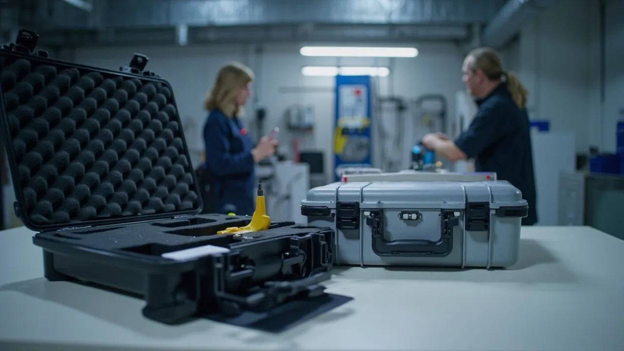
Transport protection for optical fiber equipment and fusion splicers is difficult because the item being protected is itself extremely fragile, and it has almost no margin for error. A standard single-mode fiber has a cladding diameter of only 125 micrometres and a core of roughly 9 micrometres, its minimum bend radius is strictly limited, and over-bending produces macrobend loss or even core fracture. A fiber connector end face is a sub-micron polished surface, where a single micrometre-scale particle, one improper mating or one residual fingerprint raises insertion loss and degrades return loss. The heart of a fusion splicer is the V-groove, the electrodes and the alignment system, and these three precision mechanisms determine splice loss; once the V-groove is contaminated or the electrode positions shift, splice quality falls persistently and is hard to recover. The correct selection logic for fiber equipment and splicer cases is therefore controlled radius, clean end faces, located mechanisms and humidity control throughout, rather than dropping the equipment into a shockproof box.
The practical pain points cluster in five areas. The first is hidden loss from uncontrolled bend radius. If a patch cord is coiled too tightly in the case, pressed by other items, or repeatedly kinked during handling, macrobend loss rises. In short-distance or low-rate scenarios this loss may be masked, but in long-distance or high-rate links it appears directly as an inadequate link budget. The second is end face contamination and scratching, the most common and most underestimated cause of failure in optical communications field work. End face contamination markedly increases insertion loss and return loss, and in high-power applications the contaminant on the end face is ablated by the laser, permanently damaging the end face. The third is loss of splicer alignment. The V-groove is the core component determining fiber alignment accuracy, with an extremely precise groove surface, so any embedded particle or scratch causes alignment error; impact damage to the electrode tips shifts the discharge position and directly affects splice quality. The fourth is moisture and condensation. Fiber and connectors are not themselves humidity-sensitive, but condensation forms a water film on end faces that attracts dust, while moisture corrodes metal parts and degrades optical adhesives; and for splicers with lithium batteries, battery transport must follow applicable requirements. The fifth is contamination from tools and consumables. Fiber cleavers, stripping pliers, alcohol bottles, lint-free wipes and spare connectors stored with the equipment generate particles and fibre in transit, and a cleaver blade is a supremely precise edge that is ruined by a single impact.
This article works through the protection logic in the order of bend radius, end faces and connectors, splicer mechanisms, patch cords and fiber management, humidity and dust control, isolation and sealing, and testing and acceptance. It provides a fiber and splicer component protection table, bend radius and fiber management points, end face cleanliness management, sealing class recommendations, a transport test plan and a specification selection table. JUNZHJIA serves optical communications equipment manufacturers, fusion splicer makers and service providers, carriers and engineering companies, data centre integrators and optical component distributors with radius-controlled insert design, clean end face cavities, dedicated splicer mechanism cavities, model-matched humidity and vibration configurations, and OEM/ODM volume delivery, manufactured and shipped worldwide by Kexin New Materials (Guangdong) Co., Ltd.
Table of Contents
- 1. Why Fiber Equipment and Fusion Splicers Need Purpose-Built Cases
- 2. Risk Profile: Bend Radius, End Face and Alignment Mechanism Failure Modes
- 3. Fiber Bend Radius and Macrobend Loss
- 4. Fiber End Face and Connector Protection
- 5. Fusion Splicer Protection: V-Groove, Electrodes and Alignment System
- 6. Patch Cords, Fiber Management and Distribution Accessories
- 7. Humidity and Condensation Control
- 8. Dust Prevention and End Face Cleanliness Management
- 9. Vibration Isolation and Cushioning: Graded Design
- 10. Sealing Class: How IEC 60529 and GB/T 4208 Apply
- 11. Custom Inserts and Cavity Schemes
- 12. Transport Testing: ISTA, GB/T 4857, ASTM D4169 and the MIL-STD-810H Note
- 13. Marking, Documentation and On-Board Accessory Management
- 14. Procurement Acceptance, AQL, Selection Table and Export Delivery
- Frequently Asked Questions
- Conclusion & Related Reading
1. Why Fiber Equipment and Fusion Splicers Need Purpose-Built Cases
The starting point is the particular combination of a fragile object and zero margin for error.
The fragility of fiber is structural, not incidental. A standard single-mode fiber has a 125 micrometre cladding and roughly a 9 micrometre core, while multimode fiber cores are 50 or 62.5 micrometres. These dimensions mean that the mechanical behaviour of fiber is entirely unlike ordinary cable: its bend radius has a definite minimum, beyond which macrobend loss appears, and smaller radii damage or break the core or cladding; its end face precision is at the sub-micron level, so any change in end face quality appears directly as a change in insertion loss and return loss; and its surface is extremely easily contaminated, with the consequences on an end face amplified by the optical system.
The precision of a fusion splicer is concentrated in three mechanisms. The V-groove passively aligns fiber through a precision V-shaped channel, and groove surface accuracy and straightness directly determine alignment accuracy. The electrodes fuse the fiber by high-voltage arc discharge, and tip position, spacing and shape determine discharge stability and splice quality. The alignment and imaging system performs further core alignment through cameras and image algorithms, with some models offering core-to-core alignment. All three share one characteristic: accuracy depends on the original assembly state, and once disturbed by shock or contamination, performance falls persistently and is hard to restore on site.
How fiber work is actually done sets the protection requirement. Fiber equipment is rarely moved from factory to laboratory in a controlled environment; it moves to construction sites, emergency repair sites and field operations. A splicer travels with a crew between equipment rooms, ducts, poles and open field; an OTDR, optical power meter and light source travel with test staff; patch cords, pigtails and distribution modules ship in volume. What these scenarios share is frequent handling, uncontrolled environment and time pressure, so the case must support fast access, clear counting and repeated use, not merely surviving the journey.
Attributing field faults is expensive. Once a fiber link fails, diagnosis usually means carrying an OTDR and locating the fault section by section, which is slow and costly. A substantial proportion of field faults originate from end face contamination or connector damage, which means protecting end faces during transport and storage is one of the most direct ways to reduce field failure rates and operating cost. This is frequently overlooked in procurement because the benefit is spread across the whole service life rather than concentrated at the point of purchase.
Compliance and safety management also matter. Splicers and test instruments with lithium batteries must meet applicable battery transport requirements. Laser safety in fiber work, covering light sources, OTDRs and high-power systems, must be managed at the working stage in accordance with applicable requirements, and a case is not a laser safety guard of any kind. Fiber shards, a broken fiber end being an extremely fine glass needle that can penetrate skin, need a dedicated collection and disposal method.
In summary, the core requirements for fiber equipment and splicer cases are controlled fiber bend radius, clean and physically protected connector end faces, located and fixed splicer mechanisms, and humidity and dust control throughout. A general selection framework is in the Instrument case selection guide.
2. Risk Profile: Bend Radius, End Face and Alignment Mechanism Failure Modes
The logistics chain for fiber equipment and splicers is typically: equipment manufacturer, distributor or branch office, then construction crews and maintenance teams, with some scenarios involving rental turnover, equipment room relocation and central purchasing distribution.
| Chain stage | Dominant stress | Typical consequence | Protection focus |
|---|---|---|---|
| --- | --- | --- | --- |
| Factory dispatch | Shock, vibration, temperature swing | Cord kinking, end face contamination, splicer mechanism shift | Radius-controlled insert, end caps, dedicated mechanism cavities |
| Distribution and warehousing | Long-term static load, humidity, repeated handling | Fiber compression, accumulated end face contamination, metal corrosion | No fiber compression, humidity control, end face cleanliness |
| Service vehicle and field transport | Sustained vibration, random shock, dust | Loss of radius control, cord tangling, cleaver damage | Graded isolation, dedicated cord cavity, tool separation |
| Sea and air freight export | High humidity, heat, condensation, low pressure, repeated handling | Condensation attracting dust, corrosion, adhesive degradation, case compression | IP67 plus pressure equalisation plus desiccant |
| Equipment room and unpacking | Frequent opening, dust, temporary placement | End face contamination, cords stepped on, tools and consumables mixed | Clean unpacking, removal sequence, position numbering |
Loss of bend radius control is the most easily overlooked failure mode. Its characteristic is the absence of any visible change: the cord looks intact while macrobend loss has already risen. Common causes are an undersized coil radius, created by coiling a cord tightly to save space; compression by other items, where a cord is pressed against the case wall by equipment or tools and forms a local small-radius bend; repeated kinking during handling, where a cord is pulled out with force and forms a sharp bend at the exit; and tangling, where loosely coiled cords entwine in transit and form knots whose radius is far below the allowable value.
End face failure takes three forms. Contamination: particles, oil, fingerprints and water film on the end face, raising insertion loss and return loss; in high-power systems the contaminant is ablated and forms a permanent pit. Scratching: the polished surface abraded by a hard object, creating a permanent scattering point. Structural damage: chipping of the ceramic ferrule end face, deformation of spring or latch, or housing cracking, preventing proper mating or accurate location. All three share one feature: they are hard to fully repair on site. Contamination can be cleaned, but scratches and chipping require re-polishing or replacing the whole cord.
Splicer mechanism failure must be understood part by part. For the V-groove: embedded particles in the groove, the most common problem, causing incomplete fiber seating and alignment error; groove surface scratching, a permanent accuracy loss; and groove base deformation. For the electrodes: tip deformation or chipping causing discharge position shift and arc instability; spacing change; and electrode holder loosening. For the alignment and imaging system: lens contamination causing blurred images and core alignment failure; changed illumination LED position; and camera module loosening under shock. For the heating groove and splice protector heater: contamination of the heating plate surface and heater deformation. The display, keypad and housing are also vulnerable zones.
Tool and consumable failure has knock-on effects. A fiber cleaver blade is a supremely precise edge, and a single impact can chip it, causing an out-of-tolerance cleave angle and hence higher splice loss. Stripping plier edges determine coating removal quality. Leaking alcohol or cleaner contaminates equipment and fiber. Loose lint-free wipes and swabs generate fibre inside the case. Tools and consumables must therefore be strictly separated from equipment and fiber.
3. Fiber Bend Radius and Macrobend Loss
Understanding the engineering meaning of bend radius is the physical basis for fiber protection design.
Two forms of bend loss. Loss caused by bending is of two kinds. Macrobend loss occurs when the bend radius falls below a critical value and part of the optical power leaks from the core into the cladding and is lost, appearing as added attenuation. Microbend loss arises from small local perturbations, such as compression by a rough surface or local stress on the coating, causing higher-order mode coupling and loss. Both share one characteristic: neither is accompanied by any visible change, and both are invisible failures.
Practical values for bend radius. The allowable minimum bend radius depends on fiber type, coating structure and service condition, and three states must normally be distinguished: the short-term bend radius during installation, usually smaller; the minimum bend radius in the long-term installed state, usually larger; and the requirement during transport and storage. Common industry practice is that the bend radius in transport and storage should be no smaller than the minimum installed bend radius, with an allowance, because shocks and vibration in transit produce momentarily smaller radii. The specific figure must come from the fiber or cable manufacturer, since standard single-mode, bend-insensitive fiber, armoured cable and indoor patch cords differ markedly and cannot share one number.
Three workable engineering principles. First, the coil radius should be set by structure, not by human care. Design a fixed-radius fiber management tray or cavity so the cord naturally follows a controlled radius, rather than relying on staff to be careful. The tray radius should exceed the minimum allowable value with an allowance. Second, avoid local load points. A cord pressed at one point forms a local small radius and microbend, so no storage or load-bearing structure may sit above the cord cavity, cords must not pass through narrow gaps, and cords must not be cinched with cable ties or clamps. Third, avoid free coiling and knotting. Loosely coiled cords entwine in transit and form knots whose radius is far below the allowable value, so cords should be individually fixed or stored in separate compartments, with both connectors fixed in place and the middle coiled along a controlled radius.
How to verify by test. Bend loss is a measurable failure: for a single cord, compare added loss before and after bending using a light source and power meter; for a whole case or link, use an OTDR to look for abnormal attenuation steps or reflection peaks. The packaging verification stage should treat bend radius and added loss as a specific verification item, re-measured after vibration and drop testing, with the difference used to judge whether the insert design works. Related verification is described in the transport testing chapter.
4. Fiber End Face and Connector Protection
The end face is the most critical and most fragile interface in a fiber link, and its protection requires physical protection, cleanliness control and structural fixation working together.
Why the end face is so sensitive. A fiber connector achieves optical coupling through physical contact between two end faces, so any change in end face quality directly changes coupling efficiency. Particles prevent full contact, creating an air gap and Fresnel reflection, and raise insertion loss while degrading return loss. Oil and fingerprints cause local absorption and scattering. Scratches create permanent scattering sources. Chipping reduces the effective coupling area. In high-power fiber systems, contaminants on the end face absorb laser energy and are ablated, forming permanent pits or even destroying the connector, which is the most important end face risk in high-power applications.
The core means of physical protection is the cap. Every unmated connector should have an end face protective cap during transport and storage. Selection and use points: the cap interior must be clean and must not shed particles, since an unsuitable cap is itself a contamination source, a common real-world problem; the cap must fix reliably without working loose; adapter ports with dust shutters should use dedicated dust caps; and caps must be quick to remove and refit, because in fast field work anything inconvenient will be skipped. For connectors used in high-power systems, use the protection method the manufacturer specifies, and in some cases a clean pad layer inside the cap.
Structural fixation and shock protection. The junction of connector and cord is a stress concentration: tensile load acts directly on the adhesive interface between fiber and ferrule, and repeated loading can pull the fiber out of the ferrule or break it inside the connector. Protection points: fix the connector body independently, never let it hang free; provide strain relief slack near the connector so it does not carry the cord weight and vibration inertia; keep the connector away from hard objects so ferrule end faces and housings do not collide; and fix both ends of a cord separately so load on one end is not transmitted to the other.
Supporting cleanliness measures. The protection scheme must be matched by on-site cleaning practice, otherwise protection in transit is undone by contamination after opening. Provide a dedicated clean consumables cavity holding a one-click fiber cleaner, lint-free wipes, anhydrous alcohol or dedicated cleaner, and a storage position for a fiber inspection scope. Delivery documentation should give the recommended end face inspection and cleaning procedure: inspect the cap and end face visually before mating, clean in a single direction with a dedicated cleaner, confirm with an inspection scope before mating, never touch the end face by hand, and never wipe it with ordinary tissue or clothing.
5. Fusion Splicer Protection: V-Groove, Electrodes and Alignment System
A fusion splicer is the most critical and most precise field device in fiber work, and its protection must be broken down by mechanism.
V-groove protection. The V-groove passively aligns fiber through a precision channel whose surface roughness, straightness and angle accuracy determine fiber seating accuracy. Failure modes include particles embedded in the groove, the most common, causing incomplete seating, alignment error and higher splice loss; groove surface scratching, a permanent accuracy loss; and groove base deformation from shock. Protection points: close the clamps or fit the protective cover as the manufacturer requires before shipping; never transport with the groove exposed, which is the single most important rule; design a dedicated cavity so the unit cannot be compressed; avoid dusty environments; and critically, the protection objective is to deny particles any opportunity to enter the groove, so dust control inside the case and low-shedding insert requirements apply to the splicer body as well.
Electrode protection. The electrodes fuse fiber by high-voltage arc discharge, and tip position, spacing and tip shape determine discharge stability. Failure modes include tip deformation or chipping from impact, causing discharge position shift, arc instability and degraded splice quality; electrode spacing change from holder loosening or shock; and electrode holder loosening. Protection points: dedicated protection for the electrode region with no compression; remove and separately pack the electrodes where the manufacturer requires, since some models have a dedicated transport protection method; separately clean-pack spare electrodes; and never place tools or other hard objects near the electrodes.
Alignment and imaging system protection. Modern splicers align cores using cameras and image algorithms, with core alignment on some models. Failure modes: lens and illumination window contamination, causing blurred images, alignment failure and inaccurate edge detection; changed illumination LED position, causing uneven image brightness; and camera module loosening under shock, causing image offset. Protection points: avoid contact and contamination around the optical windows and lenses; shut down or lock the relevant mechanisms as instructed before shipping; and avoid the display and the lens cavity sharing a cavity.
Heating groove and splice protector heater protection. A contaminated heating plate produces uneven heating of the splice protector, and a deformed heater reduces heating performance. Protection points: no compression or foreign objects in the heating area, and clean and shut down as the manufacturer requires before shipping.
Other vulnerable zones. The display is the most easily crushed and needs independent protection with no shared cavity with hard objects. The keypad is vulnerable to local compression. The battery in lithium-powered models must meet applicable battery transport requirements and should have a dedicated cavity, freedom from compression, protection against short circuits and avoidance of prolonged extreme temperatures. The handle and housing are vulnerable to impact and cracking, and the wind shield and guards are thin-wall parts vulnerable to deformation.
| Component | Failure mode | Consequence | Protection point | Key prohibitions |
|---|---|---|---|---|
| --- | --- | --- | --- | --- |
| V-groove | Embedded particles, surface scratches, base deformation | Alignment error, higher splice loss | Close clamps or fit cover before shipping, dedicated cavity, low-shedding insert | No transport with the groove exposed |
| Electrodes | Tip deformation, chipping, spacing change | Unstable discharge, degraded splice quality | Dedicated region protection, removal per instructions, clean-packed spares | No hard objects near the electrodes |
| Alignment and imaging | Lens contamination, LED position change, module loosening | Alignment failure, blurred image | Keep optical windows clean, lock per instructions, dedicated cavity | No shared cavity with the display |
| Heating groove | Surface contamination, heater deformation | Uneven splice protector heating | No compression or foreign objects, shut down per instructions | No foreign objects left inside |
| Display | Crushing, scratching | Inoperable | Independent protection, no shared cavity with hard objects | No load on the screen |
| Battery | Compression, short circuit, heat | Swelling, failure, safety risk | Dedicated cavity, no compression, extreme temperature protection | No mixing with metal parts |
| Cleaver | Blade edge chipping | Out-of-tolerance cleave angle, higher splice loss | Blade guard, dedicated cavity, separated from equipment | No impact with hard objects |
6. Patch Cords, Fiber Management and Distribution Accessories
Patch cords and distribution accessories are the highest-volume and most easily uncontrolled part of fiber protection.
Cord types and their differences. Common field types include single-mode patch cords, usually yellow, for long-distance and high-bandwidth links; multimode cords, usually orange or aqua; armoured cords, with a metal loose tube giving crush and rodent resistance but a larger bend radius; field tactical cable, for field and emergency use, with high tensile and crush resistance but greater bulk and weight; and high-power cords for high-power systems, with stricter end face preparation and protection requirements. These differ markedly in bend radius, crush resistance and end face requirements, so cavities and coil radii must be designed by type.
Three ways to manage fiber coiling. A fiber management tray is a circular former of fixed radius on which cords coil around the outer edge with both connectors fixed to the tray, suitable for long cords. Compartmentalised cavities place each cord in its own compartment with a controlled internal coil radius, suitable for many short cords, with the advantage of clear access and no tangling. A fiber management box is a standalone container suitable for field carrying and temporary storage, acting as a box within a box inside the case. All three must provide a controlled radius, fixed ends and no stacking.
Managing distribution accessories. Common accessories include adapters and flanges, with ceramic or metal sleeves vulnerable to impact deformation and contamination; attenuators, which are precision optical items; splitters and WDM modules, whose internal fiber structures are vulnerable to bending and compression; distribution modules and splice trays, plastic structures vulnerable to compression; and closures, vulnerable to compression and water ingress. Management points: dedicated cavities, no stacking, easy counting and separation of optical items from metal items.
Tools and consumables must be strictly separated. Cleavers, stripping pliers, Miller pliers, scissors and screwdrivers are tools; anhydrous alcohol, dedicated cleaner, lint-free wipes, swabs, splice protectors and caps are consumables. Their shared risks are generating particles and fibre, leaking liquid and impacting optical items. Management points: physical separation of the tool cavity from fiber and equipment cavities; independent fixation and leak protection for liquid containers so leakage cannot contaminate equipment or fiber; resealing lint-free consumables after use; and a dedicated cleaver cavity with the blade guard fitted.
Collecting fiber shards. A broken fiber end is an extremely fine glass needle that can penetrate skin and is very hard to clean up. The case should therefore provide a position for a dedicated shard collection container with a lid, and delivery documentation should state the shard disposal requirement. This is one of the most frequently overlooked safety details in fiber work.
7. Humidity and Condensation Control
The focus of humidity control is not the fiber itself but end face adsorption, metal corrosion and adhesive degradation.
Four paths by which humidity causes harm. First, condensation forms a water film on end faces, which attracts dust and forms a contamination layer while altering the optical properties of the end face. Second, moisture corrodes metal parts: connector housings, adapter sleeves, flanges, tools and fasteners corrode in prolonged high humidity. Third, adhesives degrade: the fiber bonding adhesive inside a connector ages under heat and humidity, causing fiber displacement or pull-out. Fourth, mould and biological contamination can grow on organic surfaces under heat and humidity, creating a contamination source. The humidity control objective for fiber equipment is therefore clear: keep end faces dry, protect metal parts and protect adhesives.
How condensation forms and how to prevent it. Condensation occurs when a surface temperature drops below the dew point of the surrounding air. Two situations are typical: container rain in a sea freight container crossing climate zones, and moving directly from cold storage into hot humid air. Prevention means reducing the absolute water content inside the case through sealing, desiccant and packing in a low-humidity environment; slowing the rate of temperature change using thermal inertia; and avoiding abrupt transfers by equalising temperature before opening. One specific warning for fiber equipment: opening the case immediately after moving from a cold to a warm environment and then mating a connector is the most likely way to produce end face condensation, and should be actively avoided.
Desiccant selection and quantity. Selection points: capacity matched to the target humidity, rate matched to the transport duration with fast-acting types for short journeys and high-capacity long-lasting types for sea freight, no dust or corrosive by-products, which matters especially for end face protection since a dust-generating desiccant is itself a contamination source, and an indicating type for visual checking. Quantity should be calculated from free internal volume, packaging material moisture vapour transmission rate, transport duration and target humidity, with an allowance, never estimated roughly.
Combining pressure equalisation with sealing. A high sealing class brings a pressure problem: sealed at low altitude and shipped at high altitude or by air, the differential loads the case structurally and makes it hard to open. Cases at IP67 and above used for fiber equipment should therefore be fitted with a pressure equalisation valve, which breathes slowly at a threshold differential while a hydrophobic and oleophobic membrane blocks liquid water and particles. Related structure and selection points are in Case pressure equalisation valve and IP67 protective case structure.
Special considerations for batteries and temperature. Lithium batteries in splicers and test instruments are temperature-sensitive: heat accelerates capacity fade and brings safety risk, while cold causes temporary capacity loss. Batteries, especially removable ones, should therefore have a dedicated cavity, freedom from compression and avoidance of prolonged extreme temperatures; transport must meet applicable lithium battery requirements, covering matters such as state of charge, packaging and marking, as determined by the carrier and applicable regulations. Related wide-temperature schemes are in Extreme temperature protective cases.
8. Dust Prevention and End Face Cleanliness Management
For fiber, dust prevention is not a comfort requirement but a functional one.
Where particles come from. The main sources inside a case are the insert material itself shedding fibre and debris through friction; packaging debris from cartons, labels and foam fragments; metal dust from tools and metal parts rubbing; desiccant dust; ingress from the outside environment when the case is not sealed; and particles carried in during use, when a cord is dragged across an equipment room floor and returned to the case. These particles span a wide size range, but the harm to an end face does not depend on size so much as on whether a particle lands on the end face and contacts it.
Three levels of cleanliness control. Level one is the cleanliness of the insert material: materials contacting fiber and connectors or sharing a sealed volume must deliver low particle shedding, low outgassing and no hard fillers. This must be established by material evaluation rather than appearance, since similar-looking foam materials can differ greatly in shedding and outgassing. A comparison method is in the Case foam material comparison. Level two is cavity isolation: fiber, connector, splicer, tool and consumable cavities must be physically separated so particles cannot migrate freely in transit. Level three is case sealing: the sealing class determines the rate at which external particles enter, and the better the seal the longer internal cleanliness is maintained.
The practical value of a box-within-a-box strategy. For connector end faces the most practical approach is a box within a box: cap the connector, place it in a small dedicated clean box, then place that in the case cavity. Every additional layer of isolation is another contamination barrier, and the clean box can be carried separately to the work position, avoiding moving the whole case to site. For high-power connectors and precision adapters this strategy is recommended.
Cleanliness requirements for unpacking and working. Delivery documentation should state: open the case in a clean area; clean the bench and tools beforehand; mate fiber immediately after removal or place it in a clean box; never touch an end face by hand; never wipe an end face with ordinary tissue or clothing; clean in a single direction with a dedicated cleaner; confirm with an inspection scope before mating; and avoid cleaving, stripping and other dust-generating work while the case is open. No packaging can compensate for contamination caused by leaving equipment open in a dusty area for a long time.
9. Vibration Isolation and Cushioning: Graded Design
Isolation must be graded by component sensitivity rather than applied uniformly.
Distinguish shock from vibration. Shock is a short, high-amplitude event such as a drop, impact or emergency stop, needing sufficient cushion stroke and a suitable energy-absorbing material. Vibration is sustained, low-amplitude oscillation from road excitation and engine running, needing an appropriate natural frequency and damping to avoid resonance. The two require different countermeasures and must be designed separately.
Grading by sensitivity. Level one: the splicer V-groove and electrode region, precision optical modules such as splitters and WDM modules, and high-power connectors, the most sensitive, needing the highest grade of isolation and dedicated cavities. Level two: the splicer body, test instruments, adapters and attenuators, and displays, moderately sensitive, needing cushioned fixation and mechanism restraint. Level three: housings, tools, consumables, cabling and protective caps, relatively insensitive, needing impact and abrasion protection. Different levels must not share a cavity or cushion layer.
Avoid the padding-more-is-better trap. Cushion material must be matched to component weight: a material that is too soft compresses fully under a heavy load and loses its stroke, while too hard a material cannot absorb energy and transmits shock unchanged. Correct practice is to select material hardness and bearing area from cushion curves using component weight, the allowable acceleration limit given by the manufacturer and the expected drop height, then verify by test. For fiber and connectors, which are light but sensitive, softer cushioning over a larger bearing area is needed, and the cushion material itself must not create local compression on the fiber.
The particular isolation situation of the fiber tray. The tray's function is radius control, but the tray itself must not become a load-bearing structure: cords must not be pressed inside it and the tray must not carry load from above. A fiber tray is therefore normally placed in a separate region of the case, such as the inside of the lid or a separate drawer, and never below heavy components.
| Component level | Representative parts | Allowable condition (typical practice) | Insert scheme | Verification |
|---|---|---|---|---|
| --- | --- | --- | --- | --- |
| Level one | V-groove and electrode region, precision optical modules, high-power connectors | Per manufacturer acceleration limit | Dedicated cavity, soft cushioning, clean packaging, dedicated caps | Vibration test plus added loss re-measurement |
| Level two | Splicer body, instruments, adapters, displays | Conventional precision equipment level | Cushioned fixation, mechanism restraint, independent display protection | Vibration and drop test plus function check |
| Level three | Housings, tools, consumables, cabling | Impact and abrasion protection | Separated fixation, surface protection, isolation from fiber cavities | Visual and appearance inspection |
10. Sealing Class: How IEC 60529 and GB/T 4208 Apply
Sealing class is a basic specification for fiber equipment cases, but its scope must be understood precisely.
Definition and recommendation. The dust and water ingress rating follows IEC 60529 internationally and GB/T 4208 in China, expressed as IP plus two digits. For fiber equipment and splicer cases:
- IP54: only for short transfers in a controlled environment, not recommended for field work or storage.
- IP65: suitable for domestic transport and normal storage, dust-tight and protected against water jets, and a common choice for indoor work and in-building turnover.
- IP66: for field conditions where hosing or heavy spray may occur, such as duct chambers and outdoor cabinet areas.
- IP67: for sea freight export, long-term storage, field operations and high-value fiber items, and the recommended class for export and field use.
- IP68: only where there is a genuine immersion risk.
Three boundaries that must be stated. First, the IP class does not indicate internal humidity; sealed with humid internal air, the case will hold that humidity, so lowering it requires desiccant and low-humidity packing. Second, the IP class says nothing about vibration isolation; the two are independent parameters and must be designed and verified separately. Third, the IP class is not laser safety protection; laser safety in fiber work must be managed at the working stage in accordance with applicable requirements, and a case is not a laser safety guard of any kind.
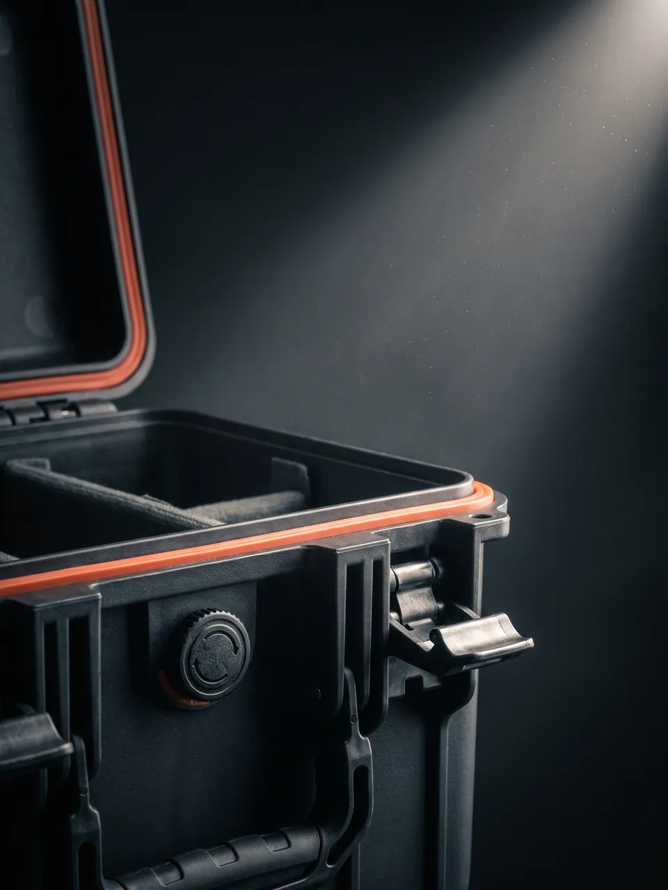
Key structures for achieving the seal. Common practice for IP67 includes a continuous closed-loop perimeter gasket with no joint in a critical position; controlled sealing face rigidity and flatness with groove tolerances matched to the gasket cross-section; multi-point latch preload design; a pressure equalisation valve; and sealed cable and interface penetrations. Related structural points are in Toolbox hinge, latch and seal structure and Case seal material selection.
Gasket replaceability and service life. The gasket is a wear part and loses sealing performance through compression set, ageing and contamination. The structure should allow replacement without special tools, no re-adjustment of the overall structure afterwards, and standardised specifications for customer sourcing. Where material flammability matters, selection and verification can follow UL94 classification with testing of the actual part.
11. Custom Inserts and Cavity Schemes
The insert is the executing layer of protection and its design quality determines the outcome.
Splicer cavity design points: profile-matched surface contact support; no load-bearing structure above the V-groove and electrode region; clamps closed or the protective cover fitted as the manufacturer requires, then fixed; independent display protection, either a separate cavity or a dedicated soft pad, never a shared cavity with hard objects; a dedicated battery cavity; cushioning on the handle and housing; and a separate tool cavity physically isolated from the equipment cavity.
Fiber and connector cavity design points: individual fixation or compartmentalised storage per cord, avoiding free coiling and tangling; a controlled coil radius above the minimum allowable value; protective caps on both connectors, each independently fixed; strain relief slack near the connectors; the box-within-a-box strategy for high-power and precision connectors; physical isolation from tool and consumable cavities; and position numbering showing cord type, length, connector type and identity.
Fiber tray design points: a fixed-radius tray or compartmentalised cavity; no load from above; not located below heavy components; fast access and easy counting; and no routing through narrow gaps.
Tool and consumable cavity design points: independent fixation and leak protection for liquid containers; a dedicated cleaver cavity with the blade guard fitted; resealed lint-free consumables; a position for the fiber shard container; strict separation of tools from fiber and equipment cavities; and a separate dry document cavity. Custom machining processes are described in EVA foam insert custom process and Custom foam inserts guide; for flexible zoning see Case removable divider system.
| Cavity type | Contents | Key design parameters | Prohibitions |
|---|---|---|---|
| --- | --- | --- | --- |
| Splicer cavity | Splicer main unit | Profile fit, mechanism covers, independent display protection | No load above the V-groove and electrode region, no transport with mechanisms exposed |
| Battery cavity | Main and spare batteries | Dedicated cavity, no compression, extreme temperature protection | No mixing with metal parts |
| Cord cavity | Patch cords of each type | Individually fixed, controlled radius, caps on both ends | No free coiling, no compression, no small-radius coiling |
| Fiber tray cavity | Long cords, field tactical cable | Fixed-radius tray, no load from above | No placement below heavy components |
| Connector clean cavity | High-power and precision connectors | Caps plus clean boxes plus low-shedding insert | No storage without caps, no shared cavity with tools |
| Tool cavity | Cleavers, stripping pliers, Miller pliers | Blade guard, independent fixation, isolated from fiber cavities | No sharing with fiber or equipment |
| Consumable cavity | Cleaner, wipes, splice protectors, caps | Leak protection, resealed wipes, independent fixation | No liquid leakage contaminating equipment |
| Shard container position | Fiber shard collection container | Lidded container, fixed position, clear marking | No shards loose in the case |
| Document cavity | Manuals, test and compliance documents | Independently sealed, moisture protected, fixed position | No mixing with consumables |
12. Transport Testing: ISTA, GB/T 4857, ASTM D4169 and the MIL-STD-810H Note
Packaging effectiveness must be verified by citable standard testing.
The ISTA series is graded by transport form and weight: Series 1 non-simulation performance tests, Series 2 partial simulation, Series 3 general simulation including temperature and humidity conditioning, and Series 6 carrier-specific and e-commerce programmes. For a single splicer case, ISTA 2A suits partial simulation; for palletised bulk dispatch, common in carrier central purchasing and distribution of fiber distribution hardware, ISTA 3E is closer to reality; and for export cargo with humidity requirements the conditioning of ISTA Series 3 is more complete. The process is described in ISTA transport testing procedure.
The GB/T 4857 series is the Chinese family of basic test methods for transport packages, covering vibration, shock, stacking and drop. For fiber equipment cases the most important are vibration testing, after which cord bend radius retention, connector displacement and splicer mechanism state must all be checked; stacking testing, which evaluates structural stability under warehouse and container stacking and must specifically confirm that the fiber tray and cord area take no load from above; and drop testing, which evaluates the integrity of case and contents in an accidental drop, where the V-groove and electrode region are the areas most needing inspection after a drop. The method is analysed in GB/T 4857 transport packaging testing.
ASTM D4169 combines distribution cycles with assurance levels and suits sea freight and intermodal transport. It is described in ASTM D4169 distribution cycle testing.
| System | Emphasis | Typical fiber equipment scenario | Common procedures |
|---|---|---|---|
| --- | --- | --- | --- |
| ISTA | General simulation and carrier specific | Export complete cases, palletised bulk dispatch | 3E, 3A, 2A |
| GB/T 4857 | Domestic road and rail | Domestic distribution, carrier delivery, equipment room relocation | Vibration, stacking, drop series |
| ASTM D4169 | Intermodal distribution cycle | Overseas projects, sea and land combined | DC12, DC13 and similar |
Additional verification items:
- Bend radius and added loss verification. This is the most direct and effective verification for fiber. After vibration and drop testing, measure the change in added loss on sample cords using a light source and power meter, and use an OTDR to check for abnormal attenuation steps or reflection peaks. If added loss rises significantly, first check whether the insert created local compression or loss of radius control.
- End face cleanliness verification. Place witness plates in the connector clean cavity and count settled particles after shipping under real conditions; for high-power connectors, confirm each one with an inspection scope after opening.
- Splicer mechanism state verification. After testing, check the V-groove for particles, whether electrode position and spacing have changed, and whether the alignment and imaging system works, which can be judged comprehensively by splicing a test fiber and measuring splice loss.
- Shock recording. Place impact indicator labels and a transport data logger inside the case and collect data on real shipments to iterate the insert design.
- Humidity verification. Place a temperature and humidity logger inside, record the humidity profile of the journey, and confirm the storage humidity limit given by the equipment and connector manufacturer was not exceeded.
- Reassembly verification. Simulate the field workflow from unpacking through placing the equipment and taking out and mating cords, recording time and problems, and use the results to optimise cavity order and labelling.
Where a customer asks to reference MIL-STD-810H, it may be used as an environmental test method basis for designing test conditions such as high-temperature storage, low-temperature storage, damp heat cycling, vibration endurance and transport drop. It must be made clear that the standard is a test method standard and not equivalent to military certification, and no military certification claim may be made. Related notes are in MIL-STD-810H as an environmental test basis.
13. Marking, Documentation and On-Board Accessory Management
Marking and documentation are part of delivery completeness and matter particularly in engineering distribution and rental turnover.
Recommended external markings:
- Equipment information: equipment name and model, serial number, configuration list, net and gross weight, external dimensions.
- Handling pictograms: this way up, keep dry, do not stack, do not roll, fragile, centre of gravity, lifting points, following general practice in the GB/T 191 package handling pictogram and GB/T 6388 transport package marking systems.
- Fiber notice marking: a prominent contains optical fiber, do not apply pressure notice, since this is the rule most easily broken in transport.
- Battery marking: equipment containing lithium batteries should carry applicable battery transport markings, which must not be obscured by case structure.
- Impact indicator labels: fixed conspicuously on the outside so an over-limit shock can be judged visually on arrival.
- Traceability code: a QR or barcode linking equipment number, inspection records, packing list and arrival record.
Recommended accompanying documentation:
- Packing list: item by item with part name, model, quantity and cavity number; cords listed individually with type, length, connector type and identity.
- Operating and maintenance documents: manual, splicer maintenance handbook covering electrode replacement and V-groove cleaning, and end face inspection and cleaning work instructions.
- Quality and test documents: factory inspection report, certificate of conformity and, where required, insertion loss and return loss test reports for cords.
- Battery transport documents: as applicable, such as test reports and safety data.
- Document storage: must be protected from moisture, contamination and compression, ideally in a sealed pouch on the outside of the case or in a dry document cavity inside, isolated from the fiber cavity.
Accessory and consumable management. Management points: dedicated cavities so nothing mixes with equipment or fiber; leak protection for liquid containers; blade guards on cleavers; resealed lint-free consumables; easy counting, with cavity labels showing name and quantity; strict separation of tools from fiber and equipment; and a fiber shard container supplied with the case.
14. Procurement Acceptance, AQL, Selection Table and Export Delivery
When buying fiber equipment and splicer cases in volume, acceptance criteria must be written into the contract.
Recommended incoming inspection items:
- Appearance and dimensions: external and cavity dimensions match the drawing; no cracks, sink marks or flash; sealing face flat.
- Sealing performance: sample check to the agreed class, continuous perimeter seal fit check, gasket replaceability confirmed.
- Structural strength: sample static load test at the rated multiple held for the specified time, confirming no permanent deformation or cracking; sample corner drop or simulated drop.
- Insert fit: trial assembly with the actual item or a gauge confirming no interference, no point contact and smooth removal; confirm there is no load-bearing structure above the V-groove and electrode region; confirm the fiber tray radius meets requirements and takes no load from above.
- Cleanliness check: visual inspection of the fiber and connector cavities for particles, fibre and odour; obtain shedding and outgassing documentation for the insert material.
- Humidity control measures: check desiccant type, quantity and placement, confirming no dust-generating type is used; humidity indicator card; pressure equalisation valve function.
- Mechanism protection scheme: trial confirmation of the V-groove cover, electrode protection, display protection and battery cavity.
- Marking and documentation: content, position and durability of markings; completeness of documents; document cavity sealing effective.
AQL sampling method. Sample size and acceptance criteria follow batch size, inspection level and AQL value. For fiber equipment cases the recommendation is a tighter AQL for critical defects such as seal failure, an insert that compresses fiber or loses radius control, a load-bearing structure above the V-groove region, insert shedding out of specification, structural cracking, or a cavity dimension error preventing assembly, and a looser AQL for minor defects such as colour variation, light flow marks or font differences. The method and tables are in Custom case acceptance and AQL.
Specification selection table:
| Cargo category | Recommended case type | Insert and protection scheme | Sealing class recommendation | Suggested transport testing |
|---|---|---|---|---|
| --- | --- | --- | --- | --- |
| Fusion splicer main unit | Zoned isolating case | Profile fit, no load above V-groove and electrodes, independent display protection, dedicated battery cavity | IP67 | ISTA 2A plus vibration plus test splice |
| OTDR and test instruments | Instrument case | Cushioned fixation, screen and interface protection, dedicated accessory cavity | IP67 | ISTA 2A plus drop plus function check |
| Standard single-mode and multimode cords | Compartmentalised cord case | Individually fixed, controlled radius, caps on both ends | IP65 | ISTA 2A plus added loss re-measurement |
| High-power and precision connectors | Clean cavity case | Caps plus clean boxes plus low-shedding insert plus dedicated cavities | IP67 | ISTA 2A plus end face inspection |
| Splitters and WDM modules | Dedicated cavity case | Independent cushioned cavities, controlled radius, clean packaging | IP67 | ISTA 2A plus added loss re-measurement |
| Cleavers and hand tools | Tool cavity case | Blade guards, independent fixation, isolated from fiber cavities | IP65 | ISTA 2A plus appearance inspection |
| Bulk distribution hardware | Palletised case sets | Uniform cavities, pallet load bearing, independent humidity control | IP65 | ISTA 3E plus stacking plus vibration |
| Field and emergency kits | Portable protective case | Modular cavities, fast access, shard container position | IP67 | ISTA 2A plus vibration plus drop |
Export and delivery points:
- Moisture and condensation are the primary risk. Sea freight containers crossing climate zones condense, and condensation forms a water film on end faces that attracts dust. An export case sealing class of IP67 or above is recommended with a pressure equalisation valve and calculated desiccant, avoiding dust-generating types, plus a temperature and humidity logger inside for arrival verification. Where required, the test plan can follow an ASTM D4169 distribution cycle.
- Structural strength for repeated handling. Export cargo passes through factory loading, port storage, vessel loading, discharge and inland transport, so case corners, lifting points and the base need reinforcement.
- Regulations and documentation. Equipment containing lithium batteries must meet applicable lithium battery transport requirements in cross-border transport, as determined by the carrier and applicable regulations; laser safety in fiber work must be managed in accordance with applicable requirements, and a case is not a laser safety guard.
- Recommended arrival delivery sequence: open in a clean area, check the packing list and record impact indicator status, inspect equipment and cord appearance before inspecting end faces, let the case equalise in temperature before opening if it has been in a cold environment, test-splice one fiber after positioning the splicer to confirm mechanism state, and confirm end face cleanliness with an inspection scope before mating cords.
- Reusable case maintenance. Establish an inspection routine for reusable cases: after each return, check gasket condition, whether the insert is deformed, whether cavities retain particles or fiber shards, whether desiccant needs replacing and whether the fiber tray radius is intact. Evaluation methods are in Protective case service life evaluation and cleaning methods in How to clean a protective case.
JUNZHJIA provides complete custom delivery capability in optical communications equipment: developing cases and inserts around splicer and optical instrument models and profiles, designing radius-controlled fiber trays and compartmentalised cavities for cords, providing multi-layer protection for connectors through caps, clean boxes and low-shedding inserts, providing isolated cavities and leak protection for tools and consumables, matching desiccant and pressure equalisation valves to humidity requirements, and supplying OEM/ODM manufacturing with stable volume delivery. Kexin New Materials (Guangdong) Co., Ltd. operates a complete chain from structural design, tooling development and rotomoulding or injection moulding through insert machining and case assembly, serving optical communications equipment manufacturers, fusion splicer makers and service providers, carriers and engineering companies, data centre integrators and optical component distributors. For a first engagement we recommend a small trial batch and physical trial assembly including bend radius and end face cleanliness verification, moving to volume supply once verified. Partner evaluation points are in How to choose a case OEM factory.
Frequently Asked Questions
Q: What is the biggest difference between a fiber equipment case and an ordinary instrument case? A: The biggest difference is that the object protected has almost no margin for error, and its failures are usually invisible. An ordinary instrument case focuses on shock and moisture protection, and damage usually shows as an appearance or function problem that is easy to spot. The two main fiber failures, macrobend loss from uncontrolled bend radius and degraded insertion and return loss from end face contamination, leave no visible trace at all. A patch cord can look perfectly intact while its added loss has already risen, which is masked in short-distance or low-rate scenarios but appears directly as an inadequate link budget in long-distance or high-rate links. The same applies to end face contamination: a single micrometre-scale particle, a fingerprint or a water film changes coupling efficiency markedly, and in high-power systems the contaminant is ablated by the laser and forms a permanent pit. In addition, a fusion splicer concentrates its precision in the V-groove, the electrodes and the alignment system, and all three depend on the original assembly state, so once disturbed by shock or contamination their performance falls persistently and is hard to restore on site. A fiber equipment case must therefore deliver controlled radius, clean end faces, located mechanisms and humidity control throughout. Q: Why does bend radius matter so much, and how is it assured in packaging? A: Because when the bend radius falls below a critical value, optical power leaks directly from the core and appears as added attenuation, and the process leaves no visible change. Three states must be distinguished: the short-term bend radius during installation, the minimum bend radius in the long-term installed state, and the transport and storage requirement. In transport and storage the radius should be no smaller than the minimum installed bend radius with an allowance, because shocks and vibration produce momentarily smaller radii. The specific figure must come from the fiber or cable manufacturer, since standard single-mode, bend-insensitive, armoured and indoor patch cord types differ markedly. Packaging follows three workable principles. First, the radius should be set by structure rather than human care, using a fixed-radius fiber tray or compartmentalised cavity so cords naturally follow a controlled radius. Second, avoid local load points: no storage or load-bearing structure may sit above the cord cavity, cords must not pass through narrow gaps, and cords must not be cinched with ties. Third, avoid free coiling and knotting: cords should be individually fixed with both connectors capped and fixed in place. Q: Why are fiber end faces so vulnerable to contamination, and how are they protected in transit? A: Because a fiber connector achieves optical coupling through physical contact between two end faces, so any change in end face quality directly changes coupling efficiency. Particles prevent full contact, creating an air gap and Fresnel reflection while raising insertion loss and degrading return loss. Oil and fingerprints cause local absorption and scattering. Scratches create permanent scattering sources. Chipping reduces the effective coupling area. In high-power fiber systems, contaminants on the end face absorb laser energy and are ablated, forming permanent pits or even destroying the connector, which is the most important risk in high-power applications. Protection in transport and storage has three layers. The first is the cap: every unmated connector should be capped, and the cap interior must be clean and non-shedding, since an unsuitable cap is itself a contamination source; high-power connectors should use the protection method the manufacturer specifies. The second is the box within a box: cap the connector, place it in a dedicated clean box, then place that in the case cavity, giving another contamination barrier and allowing the box to be carried to the work position. The third is structural fixation and strain relief: fix the connector body independently rather than letting it hang, and leave slack near the connector so it does not carry cord weight and vibration inertia. The case should also have a dedicated clean consumables cavity for cleaners, wipes and an inspection scope. Q: What is most easily damaged in a fusion splicer during transport? A: What is most easily damaged are the precision mechanisms that determine splice accuracy, and the damage is often only discovered in use. The V-groove comes first: it passively aligns fiber through a precision channel, and embedded particles, groove scratches or base deformation all cause incomplete seating and alignment error, raising splice loss. The electrodes come second: tip deformation or chipping, spacing change or holder loosening all shift the discharge position and destabilise the arc. The alignment and imaging system comes third: contamination of lenses and illumination windows blurs images and defeats core alignment, while a camera module loosened by shock causes image offset. The heating groove comes fourth: surface contamination or heater deformation produces uneven heating of the splice protector. Beyond those, the display is the part most easily crushed, the battery carries compression, short-circuit and heat risks, and the fiber cleaver blade can chip in a single impact and then produce an out-of-tolerance cleave angle. Protection therefore means closing the clamps or fitting the protective cover as the manufacturer requires, never transporting with the groove exposed, keeping all load-bearing structure away from above the V-groove and electrodes, protecting the display independently with no shared cavity with hard objects, giving the battery its own cavity, and fitting a blade guard on the cleaver while separating it strictly from equipment and fiber. Q: What is the risk of opening the case after transport from a cold environment? A: The main risk is condensation, and in fiber applications it is more serious than for most equipment. When the surface temperature of equipment and fiber falls below the dew point of the surrounding air, water vapour condenses on the surface. Two situations are typical: container rain in a sea freight container crossing climate zones, where falling night-time temperatures cool the container walls and internal vapour condenses on walls and cargo, and moving directly from cold storage or winter transport into a warm humid indoor environment. The consequences are significant for fiber equipment: condensation forms a water film on connector end faces, and the film attracts dust to form a contamination layer while changing the optical properties of the end face, and moisture corrodes metal parts and degrades the adhesive inside connectors. The operation most to be avoided is taking the case from a cold environment and immediately opening it and mating a connector. The right approach is to let it stand in the new environment so the temperature equalises before opening, then avoid mating immediately, inspecting and if necessary cleaning the end face first, and confirming with an inspection scope before mating. On the packaging side this is supported by a sealing class of IP67 or above, a pressure equalisation valve and a calculated desiccant, plus a temperature and humidity logger inside for arrival verification. Q: What sealing class does a fiber equipment case need? A: The recommendation is IP65 for indoor domestic turnover and IP67 for export, long-term storage and field operations, under IEC 60529 and its Chinese counterpart GB/T 4208. Fiber equipment is not itself humidity-sensitive, but condensation forms a water film on end faces that attracts dust, and moisture corrodes connector metal parts and degrades internal adhesives, with condensation in a sea freight container crossing climate zones being the scenario that most needs guarding against; field and duct chamber work also brings spray and brief immersion risk. Three boundaries must be stated clearly. First, the IP class describes the case resistance to water and particles and does not indicate internal humidity, so lowering humidity requires desiccant and low-humidity packing. Second, the IP class says nothing about vibration isolation; the two are independent parameters that must be designed and verified separately. Third, the IP class is not laser safety protection; laser safety in fiber work must be managed at the working stage in accordance with applicable requirements, and a case is not a laser safety guard. In addition, at IP67 it is advisable to fit a pressure equalisation valve, otherwise a pressure differential across altitude changes or air freight loads the case structurally and makes it hard to open. Gaskets should be replaceable, with spare supply agreed in the contract. Q: How should patch cords and connectors be arranged inside the case? A: The essentials are individual fixation, controlled radius, protected ends and freedom from compression. In practice: first, avoid free coiling, since loosely coiled cords entwine in transit and form knots whose radius is far below the allowable value, so each cord should be individually fixed or stored in its own compartment; second, let structure set the radius, using a fixed-radius fiber tray or compartmentalised cavity so cords naturally follow a controlled radius, with the tray radius above the minimum allowable value plus an allowance; third, cap both connectors and fix them independently in place, with strain relief slack near each connector so it does not carry cord weight and vibration inertia; fourth, keep all load off the cord cavity, so cords are not pressed by other items and the tray is not located below heavy components; fifth, use a box-within-a-box strategy for high-power and precision connectors, combining a cap, a clean box and a case cavity for both an extra contamination barrier and convenient carrying to the work position; and sixth, physically separate the cord cavity from tool and consumable cavities, because metal dust from tools and fibre from consumables are the main end face contamination sources. Finally, label each cavity with cord type, length, connector type and identity for fast counting and removal. Q: What should be considered when transporting a fusion splicer with lithium batteries? A: Four points matter, and the specific requirements are determined by applicable regulations and the carrier. First, the compliance precondition: equipment containing lithium batteries is generally subject to dedicated lithium battery transport requirements in transport, especially cross-border and by air, covering packaging, marking, accompanying documentation and state of charge, so requirements should be checked at quotation and logistics planning stage rather than discovered at dispatch. Second, physical protection of the battery: give it a dedicated fixed cavity, avoid compression and puncture, and avoid mixing it with metal parts to reduce short-circuit risk; removable batteries are best packed separately. Third, temperature management: heat accelerates capacity fade and brings safety risk while cold causes temporary capacity loss, so prolonged extreme temperatures should be avoided and thermal buffering considered on routes crossing climate zones. Fourth, state management: for long-term storage, keep the battery within the charge range the manufacturer recommends and inspect periodically for swelling or leakage. It is worth stressing that lithium battery safety and compliance requirements sit within transport and operational management, and a protective case provides mechanical protection and thermal buffering but cannot replace any lithium battery transport compliance requirement. Q: Why must fiber tools and consumables be stored separately from the equipment? A: Because tools and consumables generate particles, fibre and leakage risk in transit at the same time, and all three are lethal contaminants for fiber end faces. Tools such as cleavers, stripping pliers, Miller pliers, scissors and screwdrivers rub against one another under vibration and generate metal dust and debris; loose lint-free wipes and swabs shed fibre; and liquid consumables such as anhydrous alcohol or dedicated cleaner contaminate equipment and fiber if they leak, potentially reacting with housing materials. Once these contaminants reach a connector end face, insertion loss and return loss degrade, and in high-power systems the contaminant is ablated by the laser and causes permanent damage. Two further risks are specific to this setting. First, a fiber cleaver blade is a supremely precise edge and a single impact can chip it, producing an out-of-tolerance cleave angle and hence higher splice loss. Second, fiber shards: a broken fiber end is an extremely fine glass needle that can penetrate skin and is very hard to clean up, so the case should provide a lidded shard container position. The right approach is to physically separate tool, consumable and liquid cavities from fiber and equipment cavities, fix liquid containers independently with leak protection, give the cleaver its own cavity with the blade guard fitted, reseal lint-free consumables after use, and state shard disposal and end face cleaning requirements in the delivery documentation.
Conclusion & Related Reading
The design core of fiber equipment and splicer cases is guaranteeing reliability through structure rather than care, under conditions of fragile objects and zero margin for error. For fiber and patch cords, what must be protected are bend radius and end faces: let structure set the radius through a fixed-radius tray or compartmentalised cavity, fix each cord individually to avoid tangling and knotting, block particles through multi-layer protection of caps, clean boxes and case cavities, and avoid connectors carrying inertial load by fixing both ends independently with strain relief. For a fusion splicer, what must be protected are three precision mechanisms: keep all load-bearing structure away from above the V-groove and electrode region and close the clamps or fit the cover as required, keep the optical windows of the alignment and imaging system clean and untouched, protect the display independently and give the battery its own cavity. The thread connecting the two is humidity control, dust prevention and graded isolation: sealing class plus a pressure equalisation valve control condensation, a calculated desiccant quantity maintains low humidity while avoiding dust-generating types, low-shedding and low-outgassing insert materials reduce particle sources, and cushioning is selected separately for each component weight and allowable acceleration limit.
For optical communications equipment manufacturers, fusion splicer makers and service providers, carriers and engineering companies, data centre integrators and optical component distributors, the sensible sequence is: first grade by component category and sensitivity, with splicer mechanisms most sensitive, precision optical modules next and cords and tools after that; then determine the cavity form, radius control method, end face protection measures, sealing class and humidity configuration for each level; then develop inserts for the main models and carry out physical trial assembly confirming there is no load-bearing structure above the V-groove and electrode region and that the fiber tray radius meets requirements; then verify vibration, stacking and drop to ISTA, GB/T 4857 or ASTM D4169, using the change in added loss, end face inspection results and test splice results before and after testing as the core evidence of effectiveness; and finally write acceptance criteria, marking systems, document lists, end face cleaning procedures and shard disposal requirements into the delivery documentation. JUNZHJIA supports the whole path from structural design, radius-controlled insert development and multi-layer connector cleanliness protection design through trial samples to volume supply, with Kexin New Materials (Guangdong) Co., Ltd. manufacturing and delivering to customer equipment models and fiber engineering requirements, so that fiber equipment and fusion splicers retain usable splice quality and link performance from factory dispatch, storage and transport through to field work.
Related Reading