

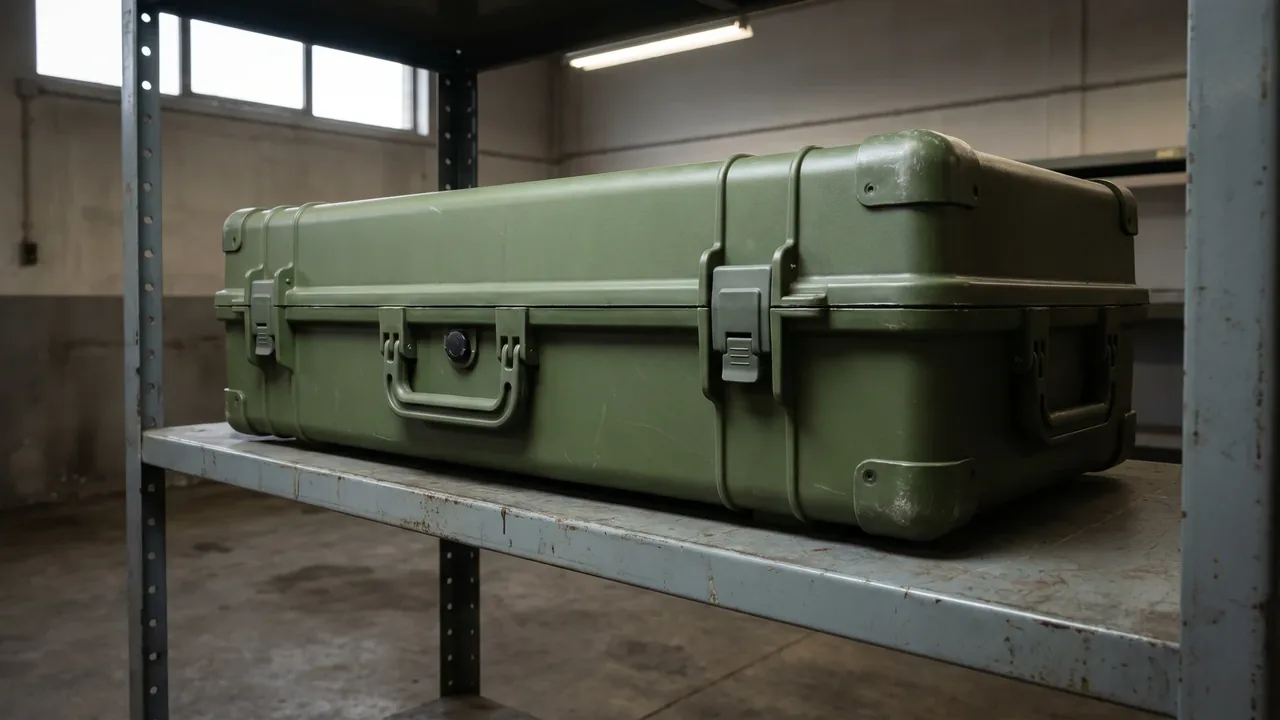
The EMI shielding case is an electromagnetically shielded protective enclosure built for electronic equipment, precision instruments, and sensitive materiel. Its task is not to "put the equipment inside" but to turn a deliverable shielding effectiveness into a box capability that can be validated, reproduced, and maintained. An EMI shielding case must, in transit, storage, and field use, block external electromagnetic fields from entering and also block the internal equipment from radiating out, holding its shielding after repeated open-close while letting any handler see at a glance "is the shielding still intact." This article unpacks, from a protective-case manufacturer's point of view, the general requirements an EMI shielding case should meet in shielding mechanism, conductive continuity, material route, shielding effectiveness and testing, internal restraint and grounding, wall penetrations, ventilation and heat, shielding-attenuation maintenance, and military acceptance, and gives procurement a checklist they can drop straight into a technical agreement. It must be stated plainly that this article discusses the packaging container only; the EMC certification, emission nature, and any defense-trade export of the equipment inside are governed by local regulations and export control requirements, and the container supplier's duty is to translate shielding effectiveness, sealing, grounding, and maintainability into a mass-producible box structure. JUNZHIJIA manufactures rotomolded and aluminum protective cases over the long term, and the experience below references this kind of volume production process.
Written from the bench of a protective-case manufacturer, this guide deliberately stays within the boundary of the container. It does not describe which electronic equipment the box holds, its frequency characteristics, or its controlled nature; those sit with the equipment authority, the EMC responsible party, and the regulator. What it does offer is the engineering reasoning a buyer can use to turn a vague "shielding case" request into a numbered technical agreement, and to ask the right questions when two quotations look identical on paper but diverge sharply on the shielding capability they actually deliver. The rest of the article walks the shielding chain link by link, from mechanism to on-site acceptance.
The Mission: Turning the Electromagnetic Environment into a Controllable Capability
The EMI shielding case faces a chain of "load, transit, store, field, recover" rather than a single trip. At loading it must let the equipment be installed by procedure with good grounding; in transit it must hold shielding effectiveness amid external field fluctuation; in storage it must keep shielding in a warehouse without mains power; in the field it must let the handler quickly judge whether shielding is intact; at recovery it must be serviced, retested, and reissued. This mission means the core of an EMI shielding case is not "sturdier" but "shields, grounds reliably, attenuation measurable, maintenance sustainable." Abstracting the electromagnetic environment into a standard box unit is the fundamental way to cut electronic-equipment support complexity, and the basis on which modern sensitive-materiel transport moves from "just wrap it" to "deliver by shielding."
Broken down, the mission has four capabilities: shielding maintainable, grounding reliable, attenuation measurable, state judgeable. Shielding maintainable means the box attenuates external fields to the required value within the rated frequency range; grounding reliable means the shell-to-equipment ground path is continuous with controllable impedance; attenuation measurable means shielding effectiveness can be retested with data; state judgeable means the shielding state at opening is readable at a glance. The manufacturer must reserve interfaces for these four in the structure: a conductively continuous shell, a reliable grounding terminal, a test window, and a shielding status indicator, all of which are the engineering details that make shielding capability real.
Concretely, an EMI shielding case earns its name only when three conditions hold together: it reaches the shielding-effectiveness requirement across the rated frequency range, the grounding and wall penetrations do not break the shielding, and the shielding attenuation stays within threshold after repeated open-close. Miss any one and the shielding case reverts to "a metal box," which is exactly the illusion shielding delivery was built to remove. The remainder of this article treats those three conditions as engineering requirements with measurable acceptance criteria, so a buyer can specify them in numbers rather than adjectives, and can reject a quotation that only promises shielding in a render.
The Core of Shielding: Conductive Continuity and Seam Control
The biggest difference between an EMI shielding case and an ordinary metal box is that it must guarantee "conductive continuity." Electromagnetic energy leaks mainly through seams, holes, and discontinuities, so the enemy of shielding is not wall thickness but the seam. The lid and shell must use a conductive gasket (conductive rubber, knitted metal mesh, conductive foam) for a full-perimeter continuous contact so current flows closed along the shell; any poorly contacting section becomes a leak path at the corresponding frequency. Therefore the gasket's conductivity, compression, and corner continuity are the core that distinguishes an EMI shielding case from an ordinary waterproof box, and the link the buyer should most quantify yet most often sees omitted from a quotation.
Conductive continuity also requires that all seams, rivets, and welds of the shell not themselves be a discontinuity. A rotomolded box needs conductive treatment inside and out with a continuous layer; an aluminum box needs conductive welds and surface treatment to stop the oxide layer breaking the current; a composite box needs a conductive layer embedded in the layup. The manufacturer should state at delivery which faces are conductive and which are structural only, avoiding treating "all-metal box" as "all-conductive box." Writing the conduction path into the technical agreement is more reliable than finding "a leak at some band" at test and then remedying, and aligns with the "sealing continuity" idea of the ordnance packing box, only the shielding case upgrades continuity from sealing to conduction.
A second layer of seam control is recovery after open-close. After repeated open-close, the conductive gasket wears or compresses, contact resistance rises, and shielding effectiveness falls. Therefore the conductive gasket should be a replaceable part, with compression margin left in the structure so the box keeps contact pressure after many cycles. The manufacturer should provide the gasket replacement interval and spare number, writing "still shielding after open-close" into the technical agreement, more reliable than replacing only after attenuation, and avoiding a whole batch of equipment losing shielding over one gasket's failure.
Material Routes: All-Metal, Conductive Coating, Composite
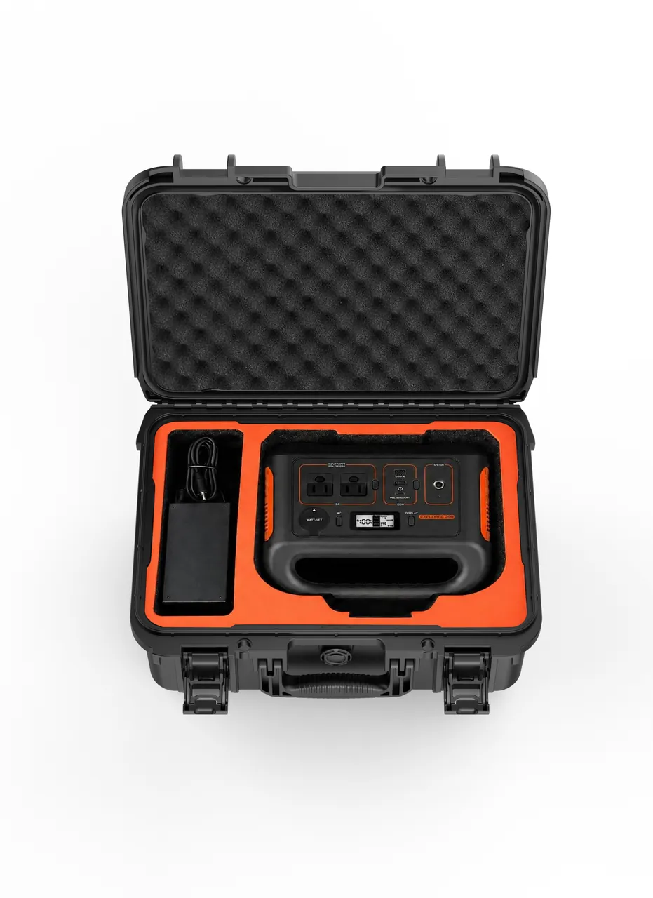
The material route of an EMI shielding case directly decides the shielding mechanism and cost. An all-metal (aluminum, steel) shell is naturally conductive with high and stable shielding effectiveness, but is heavier, costs more with size, and the aluminum surface oxidizes and needs treatment; a conductive-coated rotomolded or composite shell covers the structure with a conductive layer, lighter and cheaper, but coating durability depends on process and conductive continuity at seams is harder to guarantee; a composite with an embedded conductive layer trades between specific strength and shielding, suiting high-value low-volume. Material is not "the more metal the better" but reverse-derived from shielding requirement, frequency range, weight constraint, and site condition. Writing the material reason as a verifiable shielding note is the core by which a buyer distinguishes a "select-by-experience" quotation.
Whichever material is chosen, the EMI shielding case should place shielding consistency on a par with single-unit effectiveness. A high-shielding prototype is easy; a thousand units all qualified is hard, so the material declaration should bind the process: weld conduction and surface-treatment parameters for all-metal, coating thickness and adhesion for coated, conductive-layer continuity for composite. The manufacturer should state at delivery which parameters decide consistency and provide first-article and periodic shielding samples. Writing consistency into the technical agreement is more reliable than finding "this one differs a lot from that one" after volume and then remedying, and avoids a batch of equipment failing collectively because of shielding scatter.
A second material consideration is weight and heat. An all-metal box shields well but is heavy and conductive, a coated box is light but dissipates heat poorly, so the choice should combine the equipment's heat need. The manufacturer should provide the material's weight and thermal notes so the buyer trades shielding, self-weight, and heat on evidence rather than shielding alone. Front-loading weight and heat into material selection is the key that keeps an EMI shielding case balanced in real use, and avoids sacrificing portability or heat to chase high shielding, causing the equipment to overheat.
Shielding Effectiveness and Testing: Frequency Range and dB
The reliability of an EMI shielding case must be defined by shielding effectiveness (SE, in dB) and frequency range, not a vague "shields well." Shielding effectiveness is the field-strength ratio at the same point with and without the box (in log terms), usually given over 10 kHz to 1 GHz or wider; different frequencies have different leak mechanisms (low frequency by magnetic field, high frequency by seam), so shielding effectiveness must state the band rather than give a blanket "high shielding." Validation should cover the rated band, typical loading, and open-close state, proving the whole band qualifies; the key is "whole band" rather than "one point," because one leaky frequency is enough to disturb sensitive equipment. Writing band and attenuation into the technical agreement is the core by which a buyer distinguishes a shielding quote from an ordinary one.
Validation should not be read only for a pass conclusion but for whether the data is reproducible. The EMI shielding case validation report should record: the test method (such as MIL-STD-285 or IEEE 299 thinking), the measurement point layout, the worst point across the band, and the attenuation change after N open-close cycles. These data feed directly back into gasket and conductive-layer improvement, where the validation budget earns its return. A supplier without band data can only promise "we shield well," while a supplier with complete data can be checked line by line. The bound object should be the real box type and typical loading, because the consistency of batch shielding shows exactly in every box reproducing the conclusion.
The deeper value is the validation-to-field loop: if the field shows interference, it should trace back to a band leak, a failed gasket section, or poor grounding, and improve accordingly. Writing this loop into the technical agreement makes the EMI shielding case not "validated once, then unchanged" but continuously converging with field data. This is consistent with the "drive improvement by validation curve" idea of the temperature-controlled case, only the shielding case replaces the curve with band attenuation.
Internal Restraint and Grounding
The liner system of an EMI shielding case has two goals: keep the equipment in place under vibration, and make the grounding between equipment and shell reliable. EVA and EPE foams fix the equipment, dividers and trays handle multi-component kits; but unlike an ordinary box, the liner must not block the grounding path the equipment needs, so the grounding terminal, conductive pad, and liner must be designed together so the equipment is both restrained and reliably grounded. Writing restraint and grounding as acceptable metrics is the core difference of an EMI shielding case over an ordinary storage box on both stability and shielding dimensions, and the link the buyer most easily overlooks yet most affects shielding.
The trade-off between custom and universal liner depends on the equipment's organization and grounding need. Fixed kitting suits a typed liner with fixed grounding positions, giving consistent shielding and restraint; ad-hoc tasks suit adjustable dividers and swappable grounding modules, using zoning logic rather than per-item cutting. Either way, the EMI shielding case should guarantee "pick on open, secure on reset," with grounding still reliable after reset. Writing the reset as a diagram on the inner lid is low-cost and high-return; if reset depends on one person, grounding and restraint drift when that person leaves, and that is the human-factor risk batch shielding fears most.
A detail often missed is grounding testability. The EMI shielding case should provide a testable grounding terminal or test point so the handler can confirm at the site with a simple method whether the grounding impedance meets standard, rather than only testing back in the lab. The manufacturer should provide the grounding terminal spec and test point position, writing "grounding testable" into acceptance, more reliable than troubleshooting after interference. Front-loading grounding testability into the structure is the essential action that keeps shielding over years of reuse, and the basis the buyer can rely on at inventory.
Wall Penetrations: Filters, Waveguides, Connectors
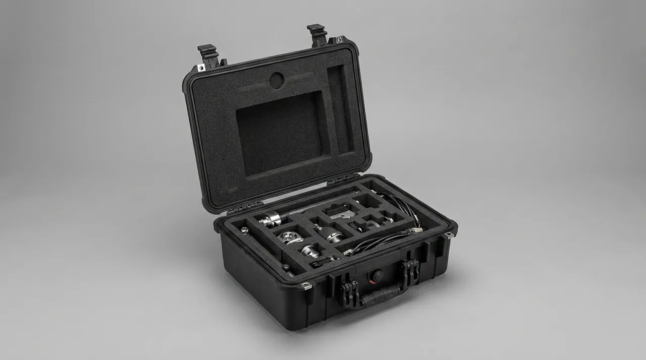
The hardest part of an EMI shielding case is not the wall but the wall penetration. Any cable, air line, or connector crossing the wall becomes a leak path, so the shielding case must provide a controlled solution: power and signal lines should have a feedthrough filter or shielded connector, ventilation openings should use a waveguide cutoff array (honeycomb), and access ports should use double conductive sealing. With poor penetration handling, the best wall shielding is ruined by one wire. Writing the penetration solution into the technical agreement is the core by which a buyer distinguishes a "metal box only" quotation, and the link shielding design should most invest in yet is hardest to procure.
Penetration design should also balance ease of use with shielding. If every penetration needs a special tool to connect, the site cannot use it fast; if the penetration is too convenient, the seal breaks. Therefore the shielding case should design a repeatable conductive structure at the penetration (such as a conductive-padded cover, a waveguide vent) so the handler connects by procedure without breaking shielding. The manufacturer should provide the penetration's repeatable open-close count and maintenance method, writing "penetration maintainable" into the delivery spec, more reliable than whole-box repair after shielding fails.
A second layer of penetration is redundancy and discrimination. When a shielding case must pass many lines, it should provide a central interface plate and shielding distribution so many lines enter in order rather than in scattered holes, reducing leak points. The manufacturer should provide the interface plate spec and mounting method so the buyer configures to the equipment need. Front-loading a central interface into the structure is the key that keeps shielding in a multi-equipment scene, and avoids multi-point leaks that are hard to locate when holes are scattered.
Ventilation, Heat, and the Shielding Balance
The classic conflict of an EMI shielding case is "to shield is to struggle to dissipate." A fully sealed metal box shields well but the internal equipment overheats, so the shielding case must provide a shielded ventilation solution: a honeycomb waveguide vent provides airflow while cutting off high frequency, a common answer; if the heat need is larger, a conducting surface can drive heat to the shell and out the wall without opening a vent. The choice depends on equipment heat and shielding band: small heat and high band prefer honeycomb waveguide, large heat and full seal prefer the conducting wall. Writing the heat solution into the technical agreement is the key by which a buyer distinguishes a shielding quote from an ordinary one, and the dividing line of whether the case balances both in real use.
The heat solution should also consider condensation and corrosion. A vent that lets external moisture in may condense and harm the equipment; a conducting wall at a different potential from the shell may cause galvanic corrosion. Therefore the shielding case should provide condensation prevention and anti-corrosion treatment, and the manufacturer should give the corresponding notes. Front-loading condensation and corrosion into the heat design is the key that keeps the case shielding and the equipment intact across climates, and a dimension ordinary cases often ignore.
A third layer of heat is maintainability. Honeycomb waveguides and conducting surfaces accumulate dust and scale over use, affecting airflow and conduction, so they should be designed cleanable or replaceable. The manufacturer should provide the cleaning interval and replacement method so the case maintains heat over long use. Front-loading heat maintainability into the structure is the key that keeps the case balanced over years of reuse, and avoids misjudging a dust-clogged overheating as a shielding problem.
Shielding Maintenance and Attenuation Monitoring
The reliability of an EMI shielding case rests on maintainability, so shielding-attenuation monitoring matters more than an ordinary box. A full service should include: checking conductive gasket compression and wear, checking the conductive continuity of seams and rivets, checking penetration shielding, checking grounding impedance, and retesting shielding effectiveness. The manufacturer should provide a service checklist, decision criteria, and replaceable-part numbers so the site acts by procedure rather than by feel. Writing the service procedure into the technical agreement is the key that keeps the shielding case shielding, and avoids "small leaks unserviced, big leaks scrapped."
A key maintenance action is attenuation retest. After repeated open-close and handling, the shielding may fall, so a retest interval and criterion should be specified so the buyer decides by data whether to continue or replace the gasket. The manufacturer should provide a simple on-site retest method and a lab retest recommendation, so shielding moves from "one factory test" to "periodically verifiable." Writing the retest into the delivery spec is the core difference of an EMI shielding case over an ordinary box on the verifiable dimension, and the data source the buyer can rely on at audit.
A second layer of maintenance is the record. Each service and retest of an EMI shielding case should leave a trace so "how many times serviced, what is the shielding now" is queryable. The manufacturer should reserve a service-record position in the structure or bind the record to the box identity so service moves from human memory to system trace. Front-loading the service record into the structure is the basis for a manageable shielding case, and the data the buyer can rely on when deciding to replace, avoiding a whole batch losing shielding over one aged gasket without anyone knowing.
Military Acceptance: Mapping MIL-STD-810H to GJB Shielding
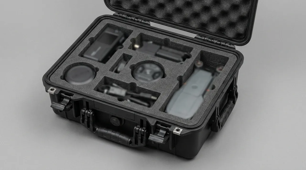
Military acceptance of an EMI shielding case usually maps to MIL-STD-810H and the corresponding GJB methods, but the focus differs from an ordinary transport case: beyond generic drop, vibration, and salt spray, the shielding case should add shielding-related verification such as band attenuation of shielding effectiveness, the attenuation change after N open-close cycles, conductive-layer retention after salt spray, and grounding reliability after vibration. Turning "shielding capability" from a claim into a set of acceptable tests is the core by which a buyer distinguishes a shielding quote from an ordinary one. The test profile should bind to the real band and use scenario, because only a test matching the actual scenario predicts field performance.
Military testing should not be read only for a pass mark, but for whether the report maps to the specific box. The EMI shielding case acceptance report should record: the worst-point attenuation across the band, the attenuation change after N open-close cycles, conduction and grounding after salt spray and vibration, and the shielding of wall penetrations. These data feed directly back into gasket and conductive-layer improvement, where the test budget earns its return. A supplier without a report can only promise verbally, with nothing to compare in an interference dispute; a supplier with a report has committed to specific test conditions checkable line by line. The bound object should be the real batch, not a generic sample, because the consistency of batch shielding shows exactly in every box reproducing the conclusion.
The deeper value is the improvement loop: aligning the field interference point with the lab failure mode forces gasket or conductive-layer optimization. For example if a band leaks in the field, the lab should measure shielding at the same band and locate the leak point, then use the gasket section and compression as the mold-change basis. Writing this loop into the technical agreement makes the EMI shielding case not "validated once, then unchanged" but continuously converging with field feedback. This is consistent with the "drive iteration by test profile" idea of the military rotomolded case, only the shielding case extends the test goal from protection to electromagnetic shielding.
Export and Compliance Documents: Trade Requirements for Shielding Containers
When an EMI shielding case is exported or moved cross-border with electronic equipment, its compliance documents are more complex than an ordinary case. Beyond the general UN packaging certification (where applicable), packing list, and material conformity, a shielding container also needs a shielding-effectiveness test report, a third-party lab number, and traceable batch records so the physical box, certificate, and report correspond one to one. Where dual-use items or controlled equipment are involved, their export is governed by local regulations and export control requirements. The typical failure is document inconsistency: certificate box type, report status, and actually shipped box do not match, often detained at the port. Writing the boundary of "container compliance" versus "equipment compliance" clearly is the premise that cross-border shielding transport avoids responsibility disputes.
Export should also separate the boundary of "container compliance" from "equipment compliance." The EMI shielding case manufacturer is responsible only for the container's shielding, structure, and sealing; the equipment's EMC certification and controlled nature are the equipment party's, and the two must not be confused. Therefore the technical agreement should state which shielding reports the container provides, who issues them, and for how long, while the equipment compliance is separately the buyer's or equipment party's responsibility. Writing the boundary clearly is more reliable than arguing "who owns this box" at the port, and avoids mistakenly pushing equipment responsibility onto the container manufacturer. It must be restated that this article discusses the container only; export is governed by local regulations and export control requirements, and the manufacturer's duty is to build compliance into the box, not to replace the equipment or regulatory body.
In practice, the EMI shielding case export documents should attach a list-style annex stating version, validity, and issuing body, re-verified against the certificate before each production, starting paperwork two weeks early typically halving clearance time. The EMI shielding case's multi-batch, long-cycle nature makes document version management more critical than single-batch export: the same box type in different years may correspond to different test standards, and if documents are not updated per batch, an old report with a new box fails at the port. Binding the document version to the production batch is the most overlooked yet most fatal link in EMI shielding case export compliance.
Long Seal and Spares: Life Management of the Conductive Gasket
EMI shielding cases are mostly reusable assets, so long seal and spare management matters more than an ordinary case. An EMI shielding box may serve years, during which the conductive gasket, conductive coating, and grounding terminal all age; without replaceable-part numbers, a whole box loses shielding over one gasket. The manufacturer should deliver a complete spare list with part numbers so the buyer procures by drawing rather than verbal inquiry. Front-loading spares into delivery is the key that keeps an EMI shielding case at low ownership cost over the whole cycle, and avoids a key shielding box being out of service for a missing part, exactly the management action reusable shielding should most use.
Seal should also include periodic shielding retest. The conductive gasket hardens and the conductive coating oxidizes under long compression and temperature change, and shielding falls, so a retest interval and criterion should be specified. The manufacturer should provide the retest method and replacement threshold so the buyer replaces by data rather than by feel. Writing retest and threshold into the technical agreement is more reliable than troubleshooting after interference, and avoids a whole batch of shielding boxes failing collectively as gaskets age without anyone knowing.
A third layer of seal is the environment's effect on shielding. Moisture and salt spray accelerate conductive-layer oxidation, so the storage environment should control humidity and be retested periodically; the manufacturer should give storage advice and a retest interval. Front-loading the storage environment into the maintenance procedure is the key that keeps an EMI shielding case usable after years of storage, and avoids discovering at opening that shielding has fallen sharply.
Procurement Checklist: Writing "Shielding Case" into a Technical Agreement
Buying an EMI shielding case should not stop at "a metal box" but turn every line above into an acceptable clause. The checklist should at least include: shielding-effectiveness band and dB requirement, conductive gasket material and replaceability, shell conduction path and seam treatment, wall penetration solution (filter/waveguide/connector), heat solution with condensation and corrosion prevention, grounding terminal and testability, liner restraint and grounding coordination, attenuation retention after N open-close cycles, retest interval and criterion, military shielding test profile with bound batch, export document list with version management, and spare part numbers with storage advice. Writing this list into the technical agreement gives the buyer the right to question quotations rather than picking boxes by feel at acceptance.
Procurement should also write "operating band" and "open-close frequency" into the requirement. The real cost of an EMI shielding case is not the unit price but whether it holds shielding in the rated band, how much attenuation falls after many cycles, and how dear the service and gasket are. Once those numbers are estimated honestly, every line of the checklist gains a budget anchor. It must be restated that this article discusses the packaging container; equipment storage, transport, and export are governed by local regulations and export control requirements, and the container manufacturer's duty is to translate shielding, sealing, grounding, and maintainability into a mass-producible box structure, not to replace the equipment or regulatory body. Writing the checklist into the agreement is the first step that turns "shielding delivery" from a slogan into an auditable engineering fact.
Same-Structure Scenes: Electronics and EMC Laboratories
The EMI shielding case's design logic is not only for the military; in electronics and EMC laboratories it is the same structure. Transport and storage of precision instruments, RF modules, sensors, and test samples equally need shielding, grounding, and traceability, differing only in band requirement and marking class. Therefore the shielding case's conductive structure, wall penetration, and retest method can migrate directly to the electronic system, letting the two share production and spares and cut total cost of ownership. The manufacturer should reserve interfaces for "civil-military common structure" rather than making incompatible molds for each version, and aligns with the "standardized zoning interface" idea of the equipment case and gear case.
The civilian scene also stresses reachability and readability. Electronic-lab handlers are often non-military, so the shielding case marking should highlight band and grounding and the reset method so anyone sees how to use before custom shape. The box should reserve multilingual or pictogram card positions so cross-region use needs no repaint to swap the list. Writing "readable" into the design is the last mile taking the EMI shielding case from military to electronic public service, and the key to its real scaled-reuse value.
The electronic scene sometimes demands stricter retest. R&D and production often require shielding to be periodically retested and filed, so the electronic version should emphasize testability and records even more than the military version, and the marking should point to the retest port so a technician reaches it without disassembly. The manufacturer can provide a retest template and document list so the customer connects to its quality system quickly. Front-loading auditability into delivery is the key that makes the EMI shielding case truly deliver "verifiable delivery" value, and avoids a qualified shielding box being unable to enter the electronic supply chain for lack of retesting.
Closing
The reliability of an EMI shielding case is written into every detail of conductive continuity and retesting: no seam leak, reliable grounding, measurable attenuation, sustainable maintenance. Buy it as a shielding-delivery system, not as a metal box. Related Reading: Temperature-Controlled Case, Equipment Case and Gear Case, Flight Case.
Frequently Asked Questions
Q: Why does an EMI shielding case stress conductive continuity; is an ordinary metal box not enough? A: Because electromagnetic energy leaks mainly through seams, holes, and discontinuities, and the enemy of shielding is the seam, not wall thickness. An ordinary metal box only solves "gets it inside," while the shielding case must also solve "no seam leak, conductive joins, still shielding after open-close." The difference is threefold: first, the lid and shell must use a conductive gasket for full-perimeter continuous contact, while an ordinary box only wants waterproofing; second, all seams, rivets, and welds must themselves be conductive, which an ordinary box ignores; third, the conductive gasket must be replaceable with compression margin, which an ordinary box never considers. Writing these three into the technical agreement lets the buyer distinguish a "real shielding case" from "just a metal box" with acceptable clauses. The typical field failure is an ordinary metal box holding sensitive equipment that leaks at some band through one poorly contacting gasket, disturbing the equipment with no visible cause, exactly where conductive continuity would have prevented it.
Q: Why must shielding effectiveness state a frequency band rather than a single dB value? A: Because different frequencies have different leak mechanisms; low frequency depends mainly on magnetic field and material thickness, high frequency mainly on seams and holes, so the same box may differ by tens of dB across bands. A blanket "high shielding" cannot tell you whether it qualifies in the band you care about, so shielding effectiveness must state the band and measurement points, and use the worst point across the band rather than an average as the acceptance basis. Validation should cover the rated band, typical loading, and open-close state, proving the whole band qualifies. Writing band and attenuation into the technical agreement is the core by which a buyer distinguishes a shielding quote from an ordinary one. The field lesson is that a box quoting a single-point dB leaks at some band, disturbs sensitive equipment, and the responsibility boundary was blurred because "band was never written," so at repair the two sides cannot even agree on what "exceeded" means.
Q: Why must an EMI shielding case design its wall penetrations specifically? A: Because any cable, air line, or connector crossing the wall becomes an electromagnetic leak path, and the best wall shielding may be ruined by one wire. Therefore the shielding case must provide a controlled penetration solution: power and signal lines use a feedthrough filter or shielded connector, ventilation openings use a honeycomb waveguide cutoff array, and access ports use double conductive sealing. Poor penetration handling is the most common shielding failure point. Writing the penetration solution into the technical agreement is the core by which a buyer distinguishes a "metal box only" quotation. Field experience is that a box ignoring penetrations passes the wall measurement in the lab and leaks the moment a cable is attached; designing the penetration together with usability (a repeatable conductive structure) is what makes it both easy to connect and leak-free in real use, and a central interface plate helps when many lines must pass.
Q: How does an EMI shielding case balance shielding and heat? A: Because a fully sealed metal box shields well but the internal equipment overheats, shielding and heat are a natural conflict. The common answer is a honeycomb waveguide vent, which provides airflow while cutting off high frequency; if the heat need is larger, a conducting surface drives heat to the shell and out the wall without a vent. The choice depends on equipment heat and shielding band: small heat and high band prefer honeycomb waveguide, large heat and full seal prefer the conducting wall. Ventilation also brings condensation and the conducting surface may cause galvanic corrosion, so the manufacturer should provide condensation and anti-corrosion notes and make the honeycomb and conducting surface cleanable and replaceable. Writing the heat solution into the technical agreement is the key to whether the case balances both in real use, and a dimension ordinary cases routinely ignore. A practical tip is to require the airflow or thermal resistance as a measured figure at the rated loading, not a drawing claim, because a vent sized for a light load often chokes once the box is fully packed, and the fully packed case is the one that actually ships.
Q: What documents differ from an ordinary case when an EMI shielding case is exported? A: Beyond the general packing list and material conformity, a shielding container also needs a shielding-effectiveness test report, a third-party lab number, and traceable batch records so the physical box, certificate, and report correspond one to one; where dual-use items or controlled equipment are involved, their export is governed by local regulations and export control requirements. The biggest failure is document inconsistency: certificate box type, report status, and shipped box mismatch often get detained. Also separate "container compliance" from "equipment compliance" — the manufacturer only owns the container shielding, structure, and sealing, the equipment's EMC certification and controlled nature are the equipment party's, and the agreement must state who issues which and for how long. The shielding case's multi-batch long cycle means the document version must bind to the production batch; an old report with a new box fails at the port, and starting paperwork two weeks early typically halves clearance time, so a shielding exporter should treat document versioning as a standing cost of the product rather than a one-off chore.
Q: Why should an EMI shielding case pay attention to attenuation recovery after open-close? A: Because after repeated open-close the conductive gasket wears or compresses, contact resistance rises, and shielding effectiveness falls, which is the most concealed shielding failure mode — the box looks intact while a band already leaks. Therefore the conductive gasket should be a replaceable part with compression margin left in the structure so the box keeps contact pressure after many cycles; the manufacturer should provide the replacement interval and spare number, writing "still shielding after open-close" into the technical agreement. The field lesson is that a box accepted on a single factory test, after a few hundred cycles, has silently lost much shielding until the equipment is disturbed. Writing attenuation retention after open-close and a retest interval into the agreement is more reliable than troubleshooting after interference, and avoids a whole batch of equipment losing shielding over one gasket's failure. A further point is that the compression margin should be specified at the rated open-close count, not at first assembly, because a gasket that measures well new can still relax after a few hundred cycles, and the relaxed state is the one the equipment actually lives with for most of its service life.
Q: Why must an EMI shielding case record its service and retest? A: Because shielding is an "invisible protection"; without service and retest records, you cannot tell how much this box still shields or whether it is due for a gasket change. Each service and retest should leave a trace so "how many times serviced, what is the shielding now" is queryable; the manufacturer should reserve a service-record position or bind the record to the box identity so service moves from human memory to system trace. Together with on-site grounding impedance measurement and periodic shielding retest, shielding moves from "one factory test" to "periodically verifiable." Writing service and retest records into the technical agreement is the basis for a manageable shielding case, and the data the buyer can rely on when deciding to replace, avoiding a whole batch losing shielding over one aged gasket without anyone knowing. A further safeguard is a spare gasket and test adapter kept with the box, so a field retest or a gasket change does not wait for a factory shipment, and the shielding continuity is preserved through the repair itself.
Q: Why should the EMI shielding case military test add a shielding-specific item rather than generic items only? A: Because generic items (drop, vibration, salt spray) only prove the box does not break, not that it "still shields before breaking," and the failure modes of a shielding case are exactly poor gasket contact, oxidized conductive layer, or penetration leak. Therefore the military test should add shielding-specific items: the worst-point attenuation across the band, the attenuation change after N open-close cycles, conduction and grounding after salt spray and vibration, and the shielding of wall penetrations; these data feed directly back into gasket and conductive-layer improvement, where the test budget earns its return. A supplier without a report can only promise verbally, with nothing to compare in an interference dispute; a supplier with a report has committed to specific test conditions checkable line by line. The report should also bind to the real batch rather than a generic sample, because the consistency of batch shielding shows exactly in every box reproducing the conclusion. The deeper value is the improvement loop: aligning the field leak point with lab failure modes forces mold change, so the shielding case converges continuously with feedback rather than staying unchanged after one acceptance.