

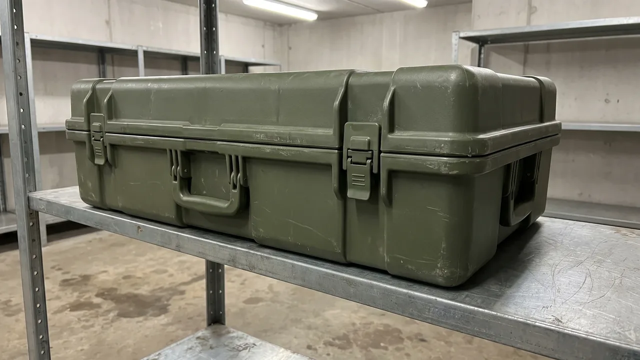
In the storage and transport chain of military equipment, the packaging container is the first layer to absorb vibration, drops, salt fog and temperature swings, and it is also the layer most often underestimated. A Military Rotomolded Case keeps being selected in this field for a reason rooted in the process itself: a Rotationally Molded Case is a seamless shell, formed in one shot from powdered polyethylene rotating inside a heated closed mold. There are no glued joints, no weld seams, and none of the knit-line weak spots that plague injection molded parts. For defense procurement offices, military trade channels and equipment integrators, judging whether a Military Rotomolded Case is genuinely adapted to military specifications is not about how heavy or thick it is. It is about whether the process advantage can be converted into verifiable test evidence: wall thickness uniformity, whole-case airtightness, and item-by-item mapping against MIL-STD-810H and the GJB test series. This article walks through that adaptation path from a manufacturer's point of view. Statements touching on military trade and export are subject to local regulations and export control requirements; this article discusses packaging containers only.
Why Military Adaptation Starts with Process Selection
The first step of military adaptation is usually not the material grade, and it is not the test report either. It is the molding process. The way a case is formed sets the ceiling for how it will behave in every subsequent test: injection molded cases carry parting lines and knit lines, blow molded cases carry pinch-off seams, and riveted or welded assemblies carry joint stress concentrations. The signature strength of a rotomolded shell is that it drives the number of joints down to zero. A military environment punishes packaging in every direction at once; there is no seam to open on a vibration table, no weld to split in a drop test, and no dissimilar-material interface to accumulate residual stress across thermal cycling. In other words, process selection determines how many failure modes you have to defend against, and rotational molding simply removes the largest category of them.
Procurement teams should therefore write the process into the technical requirement at project initiation. If the need is heavy loads, shock resistance and long-duration field storage, then a one-piece rotomolded body should be named as the preferred process route in the specification, together with a demand for documented process capability. When JUNZHIJIA takes on a defense packaging project, we typically build a correspondence table early in the proposal stage that links the molding method, the wall thickness strategy, the insert layout and the planned test items, so the buyer can see the causal chain from process to structure to test before the contract is signed. The value of this exercise is avoiding rework later: once the mold is finalized, every structural change costs far more than the same change argued out on paper during the front-end review. Military adaptation is never about squeezing an off-the-shelf product through a test; it is a design effort that starts at the process source.
How Rotational Molding Forms a Seamless One-Piece Shell
The rotational molding process can be reduced to four steps: charging, heating and rotating, cooling, and demolding. A metered charge of rotomolding-grade polyethylene powder is loaded into a closed mold, which then enters the oven while rotating simultaneously around its primary and secondary axes. Gravity and centrifugal effect spread the powder uniformly across the cavity wall, where it melts and sinters layer by layer. Once enough heat has accumulated, the mold moves to the cooling station, where it keeps turning under forced air or water mist until the part shrinks and stabilizes enough to be released. No pressure is applied at any point; the resin flows and coats the wall under its own weight, so the finished part carries essentially no flow-induced orientation stress. The body runs continuously from floor to sidewalls to lid, one uninterrupted piece of material.
For a Military Rotomolded Case, this principle delivers three direct benefits. First, a double-wall body can be formed in a single shot: the outer shell and inner shell are connected by ribs molded at the same time, creating a natural structural sandwich that gains rigidity and, once filled with polyurethane foam, thermal insulation. Second, corner radii can be made far larger than injection molding would tolerate, which lowers the stress concentration factor; in drop events the corners touch down first, and generous radii are exactly what keeps them from shattering. Third, local features such as the case opening, hinge bosses and latch seats can be pre-formed in the mold itself, reducing secondary machining. The manufacturer has to plan all of these features during mold design, because although rotomolding molds are cheaper to modify than injection tools, the design discipline is just as strict; the more thoroughly the geometry is checked in CAD before cutting, the smaller the dimensional drift after demolding. Draft angles and surface texture also deserve early attention: polyethylene shrinks noticeably as it cools, so vertical walls need enough draft to release cleanly, and a textured cavity not only hides the orange-peel character of the process but also masks minor handling scratches over a long service life. Parts that come out of the mold with the right shrink allowance go straight to trimming and hardware fitting without rework, which is one of the quiet ways a disciplined molder keeps military schedules on track.
Wall Thickness Uniformity: The First Technical Gate for Acceptance
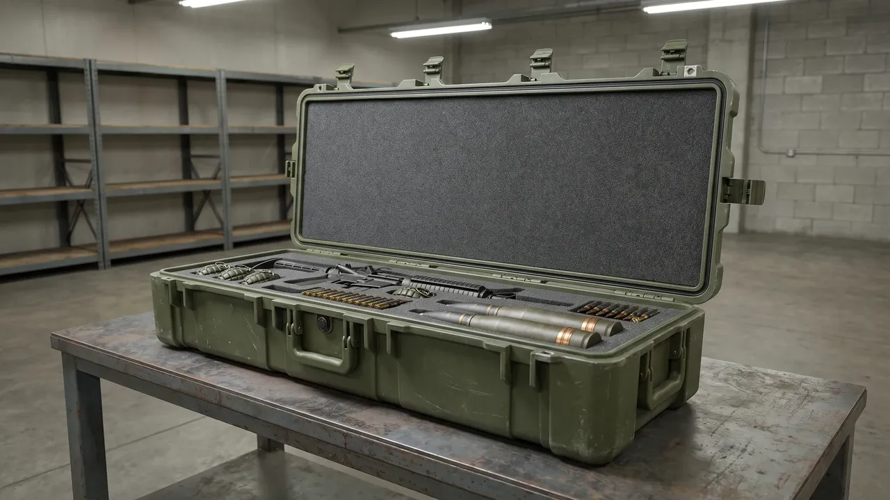
If one-piece construction is the talent rotational molding is born with, wall thickness uniformity is the exam it must pass. Because the process applies no pressure to force resin against the wall, thickness distribution depends entirely on the rotation ratio, the heating curve, the powder particle size and the thermal conductivity of the mold. Any parameter that drifts leaves a signature on the part: corners run thick, flat panels run thin, or a systematic bias appears between batches. Military acceptance typically requires the wall thickness tolerance in load-bearing zones to fall inside a stated band, and the manufacturer must document it with grid-pattern ultrasonic thickness measurements and a thickness distribution map, not just a nominal figure.
From an engineering standpoint, thickness uniformity drives three core properties: impact energy absorption, stacking stiffness and low-temperature brittleness risk. Panels that are too thin crack in cold-weather drops; corners that are too thick lengthen the cycle, raise internal stress and push cost up for no structural return. The sensible approach is to allocate thickness along the load path, thickening the pressure zones and lifting zones while replacing bulk thickness on large flat panels with ribs. The general methodology is discussed in our wall thickness structural design article (see /news/wall-thickness-structural-design/). Buyers should specify the measurement points and sampling rules in the acceptance specification and require thickness records for every batch. That is far more binding than a vague phrase such as uniform wall thickness, and it puts both parties on the same drawing when they discuss what acceptance actually means. A signed thickness map also becomes the baseline for batch-to-batch comparison later in production, which is where most disputes would otherwise surface.
Inserts and Ribs: The Mechanics Behind Lifting, Stacking and Latching
The rotomolded body is plastic, but military service forces it to interact with the metal world: lifting lugs take sling loads, fork pockets take tines, hinges survive tens of thousands of open-close cycles, and latching rods transmit compression. All of that load transfer depends on pre-molded metal inserts working together with the rib network. Inserts are fixed onto mold pins before the powder is charged; during molding the molten resin flows around them and, as it cools and shrinks, locks them mechanically. The pull-out strength of a properly molded insert far exceeds what a post-molded heat stake or adhesive bond can achieve. Insert material is usually stainless or zinc-plated steel to prevent galvanic corrosion against the polyethylene, and insert placement must avoid the thinnest zones of the shell, with local thickening or rib backing where loads demand it.
Ribs carry the stiffness task. The double-wall gap and the internal rib grid determine the bending and torsional stiffness of the whole case, and in stacking, the weight of the upper case travels through the corners and the rib grid into the load-bearing bands of the case below. Poorly placed ribs turn into stress concentrators during drops, so rib roots need generous fillets and the rib height to wall thickness ratio has to stay within the range where buckling does not threaten. The general rules of rib layout are covered in our reinforcement ribs article (see /news/case-reinforcement-ribs/). Our experience on military programs is that the insert and rib layout should be rehearsed with finite element analysis before the mold is cut, simulating four-point lifting and a five-high stack, and that the calculation results should be translated directly into mold drawings. Testing then confirms a design instead of substituting for one.
Rotomolded HDPE: Temperature, Weathering and Chemical Endurance
Rotomolding-grade polyethylene is the backbone material of military cases, and selection turns on three attributes: low-temperature toughness, the weathering package and chemical resistance. Low-temperature toughness comes from the resin's brittleness temperature; cross-linkable grades and certain ethylene copolymer grades keep high impact strength in severe cold, which matters for arctic training deployments and high-altitude airdrop scenarios. The weathering package relies on carbon black and UV stabilizers in the compound: military shells typically run in black or dark natural carbon-black-loaded material, where carbon black acts not just as pigment but as a highly efficient UV screen, and combined with hindered amine stabilizers it supports years of outdoor exposure. Aging assessment methodology is covered in our UV aging test article (see /news/uv-aging-test-for-cases/). On chemical resistance, polyethylene is stable against most acids and alkalis, salt fog and fuel oils, so coastal, harbor and field fuel-convoy environments do not swell or stress-crack the shell.
Two details at the material level are easy to overlook. The first is heat deflection control: polyethylene's continuous service ceiling is well below that of engineering plastics, and a case stored on a sunlit deck reaches surface temperatures far above ambient air temperature, so the design must reserve stiffness margin for the hot condition to keep the hinge region from creeping and the lid from sagging. The second is regrind control: military programs should specify virgin material with resin batch certificates, because regrind pulls down both impact strength and weathering life, and any permitted regrind percentage has to be locked in the contract, preferably at zero. Material certificates, retained batch samples and archived molding parameters together form the three-legged stool of material traceability on a rotomolded case, and buyers who ask for all three at quotation stage screen out suppliers who cannot hold the line in production.
Mapping MIL-STD-810H and GJB Tests onto a Rotomolded Shell
The value of military testing lies not in the certificate but in the correspondence between each test method and a real transport threat. Among the MIL-STD-810H methods most relevant to a rotomolded case are Method 501 and 502 for high and low temperature, confirming dimensional and functional stability of the shell and liner under extremes; Method 503 for temperature shock, simulating loading and unloading across climate zones during airlift; Method 514 vibration and Method 516 shock, standing in for road transport and handling drops; Method 509 salt fog, examining corrosion behavior in coastal and shipboard service; and Method 507 humidity, checking how the sealing system holds up through humid cycling. The GJB series, such as GJB 1181 and GJB 150A, shares much of its methodology with the 810 family, with levels and cycle counts set by the national military standard, so the two can be laid out in a mapping table and benchmarked item by item. Systematic coverage is available in our MIL-STD-810H compliance article (see /news/mil-std-810h-case-compliance/) and our GJB military standard case article (see /news/gjb-military-standard-case/).
For a rotomolded case, the point of test mapping is to close the loop between structure and method: record fastener torques and seal compression before vibration and re-measure after; run drop tests with the case loaded to its service weight rather than as an empty showpiece; and after salt fog, disassemble the hardware to confirm corrosion has not crept toward the sealing faces. The manufacturer's job is to trace every data point back to a design parameter, wall thickness, rib placement, insert specification, seal compression ratio, so the whole package forms a reproducible chain of evidence. Test combinations and levels must ultimately be fixed per equipment category and the ordering authority's requirements, subject to local regulations and export control requirements; this article discusses packaging containers only. Buyers who understand the mapping can also negotiate intelligently about which tests are witnessing rights and which are documentation reviews.
IP67 Sealing: Gaskets, Pressure Equalization Valves and Whole-Case Tightness
IP67 has a very specific meaning: no ingress of water when the case is briefly immersed. Achieving it on a Military Rotomolded Case is a system effort, not a single component. The first line of defense is the body itself, since a one-piece shell has no seams by construction, and the flatness of the opening flange comes from the mold and tooling; the truer the flange, the more uniform the gasket compression. The second line is gasket selection: foamed silicone and solid EPDM are the mainstream routes, the former offering better compression recovery across wide flanges, the latter offering wear and tear resistance for high-frequency opening, with cross-section shapes such as lip, D and hollow rectangle matched to the flange gap and clamping force. Gasket aging and replacement intervals are covered in our seal aging article (see /news/case-seal-aging/).
The third line is the one most often forgotten: the pressure equalization valve. A sealed case traveling between plateau and sea level, or sitting through day-night temperature swings, builds pressure differential across its walls; negative pressure sucks the gasket inward and raises opening force, while positive pressure can lift a sealing face locally. A manual or automatic equalization valve vents a whisper of air once the differential crosses a threshold, relieving pressure without breaking the watertight path. Its principle and selection logic are detailed in our pressure equalization valve article (see /news/case-pressure-equalization-valve/). Whole-case tightness is verified either by the vacuum decay method, reading a leak rate off a pressure curve, or by immersion, watching for bubbles, and both methods belong in the acceptance protocol. Our recommendation at JUNZHIJIA is that IP67 should not remain a sampling item at final inspection but a full first-article confirmation for every production batch, paired with in-process control of seal compression. That is how airtightness stops being a test result and becomes a manufacturing capability.
Custom Liners: From Equipment 3D Models to Compartmented Cushioning
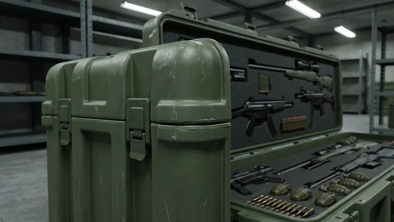
The shell is the exoskeleton; the liner is the layer that actually touches and protects the equipment. Military hardware carries optical windows, servo mechanisms, cable connectors and protruding handles, and a generic foam cutout cannot satisfy location and cushioning at the same time, which is why compartmented custom liners are standard fit on military rotomolded cases. Design input starts from the equipment 3D model: the manufacturer divides the model into bearing surfaces, clearance zones and extraction paths, decides where each item is supported, and allocates cushion thickness per item according to weight and fragility. EVA provides high support stiffness for heavy metal assemblies, EPE is softer and suits surface-sensitive parts, and molded composite liners can layer the two materials. The cushioning structures and compartment processes are described in our custom foam inserts article (see /news/custom-foam-inserts/).
Liner design must also serve efficiency of use. The compartment layout should mirror the sequence in which items are drawn, with frequently used items up top and spares below, so unpacking time stays predictable. Accessory bays hold test cables, consumables and accompanying documents, and are marked with distinct colors or laser-etched labels. For projects with humidity and corrosion concerns, the liner can additionally integrate a desiccant bay and positions for vapor-phase corrosion inhibitor bags, fixing the anti-corrosion media at defined change points rather than scattering them loose inside the case. The first liner version is normally CNC-routed for fast validation, and the real equipment is test-fitted to confirm extraction paths before the design is frozen. The whole flow depends on the buyer providing either physical units or accurate 3D data early, because the precision ceiling of the liner is always set by the precision floor of the input data.
Stacking, Lifting and Fork Handling: Structure and Test Loads
In warehousing and transit, a military rotomolded case faces three canonical load cases: stacking, lifting and fork handling. Their structural responses differ completely, and the design must satisfy each one separately. Stacking loads travel vertically and test the creep resistance of the corner columns and load-bearing bands: polyethylene deforms under long-term static load, so the crown deflection of a five-high stack after a year of storage must stay inside limits, which means the stacking design has to use creep-derated allowable stress rather than short-term compressive strength. Test methods and pass criteria are discussed in our stacking load test article (see /news/stacking-load-test-for-cases/), and the structural details of case stacking are covered in our stacking structure article (see /news/case-stacking-structure/).
Lifting and fork handling are dynamic loads. In a four-point lift the base bends, sling angles change the direction of force on the lugs, and the resin around each insert must have enough thickness and rib backing to resist pull-out. Fork handling requires the pocket opening height, depth and the case center of gravity to be matched so a laterally offset tine cannot tip the case. Top-lift cases usually carry metal lug seats at all four top corners, tied through to the base load path so sling tension feeds straight into the vertical load-bearing structure; skid-base cases mold fork pockets and lashing points into the underside, compatible with palletized transport and deck tie-down. All three load cases point to the same conclusion: the mechanical design must be reasoned backward from the usage scenario. Buyers should state the stacking count, the lift method and the forklift class in the technical requirement, so the supplier's test plan has a concrete target instead of a guess. Lashing and tie-down deserve a line of their own in the specification, because transport vibration works the anchor points thousands of times at modest force, and a lashing point that survives a static pull test can still fret and loosen at its insert root after a long convoy move; specifying the rope or strap type together with the anchor layout closes that gap on paper before it opens in service.
Batch Consistency and Traceability in Military Supply
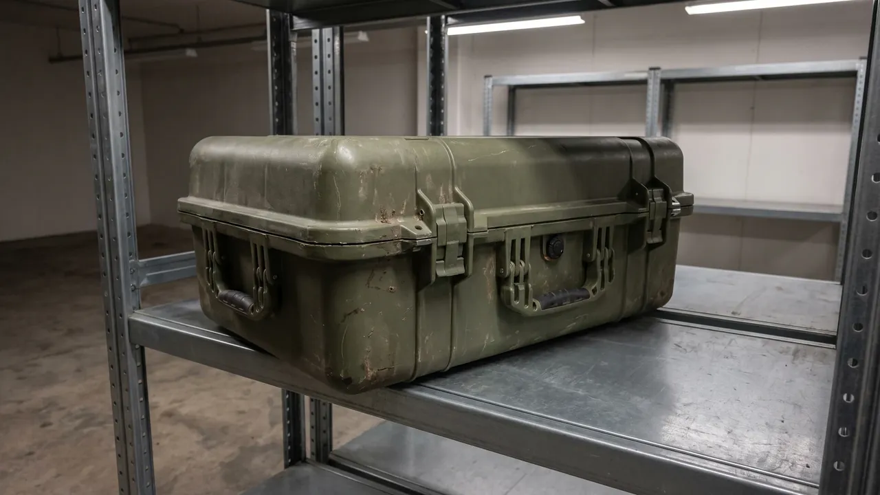
Making one good case is not hard; making every case identical is. Rotational molding carries many variables, resin batch, particle size distribution, oven zone temperatures, arm rotation speeds, cooling rate, and any drift among them can push case performance outside the acceptance window. Consistency therefore has to be built on a system, not on a veteran operator. At the manufacturer level this looks like: incoming resin retained per batch with inspection certificates; full first-article inspection plus in-process patrols, with key measurement points on control charts; a parameter card for every mold that fixes charge weight, primary and secondary arm speeds, zone setpoints and cycle time as controlled documents; and first, middle and last parts of each batch archived with matching serial numbers, forming a per-case parameter file. Identification starts with engraved marks at the factory and extends into the data layer, and the QR and asset-code approaches are described in our asset tracking article (see /news/case-asset-qr-code-tracking/).
Buyers can pull consistency into the contract through three kinds of clauses. First, a key characteristics list, wall thickness points, seal compression, insert pull-out force, stacking height and duration, with a rule that changes to these characteristics require written approval. Second, a sampling and disposition scheme: the acceptance sampling plan, judgment criteria, and the route for nonconforming batches including rework, return or concession with documented boundaries. Third, record retention: how long traceability records are kept and in what form they are delivered. Annual requalification adds a fourth pillar worth considering on long-running programs, re-running the drop and sealing tests on a random production case every year to confirm the process has not quietly wandered, with results shared to the buyer as standing evidence. Military supply chains usually demand more rigorous records than commercial orders, and whether a supplier can actually run a documented system shows during prototyping, because a vendor who cannot produce a complete parameter file for samples will only be worse at production scale. Consistency is process control, and the evidence of process control is precisely those records that look trivial from the outside.
Injection, Blow Molding and Rotomolding: Where Each Process Wins
The three plastics processes have clear territories. Injection molded cases run at high efficiency, finish with fine surfaces and cost little per unit at high volume, which suits mid-size and small products; the penalties are heavy tooling investment, unavoidable knit lines and a press tonnage ceiling on part size. Blow molding shines on thin-wall hollow parts at low cost, but pinch-off seam strength and thickness control lag rotomolding, and stacking and drop performance suffer accordingly. Rotomolding runs the other way: unit cost is flat against volume, molds are inexpensive and easily modified, and there is no hard size ceiling, at the price of long cycle times, an orange-peel surface texture and a material palette dominated by the polyethylene family. A systematic comparison is available in our rotomold versus injection article (see /news/rotomold-vs-injection-case/).
Translated into procurement language: when the requirement is small or mid size, high annual volume and weight sensitivity, injection wins on economics; when the requirement is large size, heavy load, mixed low-volume models and an integral double-wall structure, rotomolding is the rational route. Military needs cluster heavily in the second group, equipment dimensions vary, unit counts per model are limited, structural demands are strict and changes are frequent, and that is exactly why rotational molding dominates the military case field. Selection should also weigh spares and repair strategy: a damaged rotomolded shell can be plastic-welded in the field, while a cracked injection shell usually means scrapping the whole case, a real availability difference for units deployed at remote sites without logistics support. No process is superior in the abstract; write the usage scenario clearly and the process choice falls out of it.
Project Workflow and Prototype Validation for Custom Cases
A custom military rotomolded case typically moves through six milestones: requirement confirmation, structural design, mold fabrication, first-article molding, test validation, and production delivery. In requirement confirmation, the equipment list, load cases, environmental profile, opening style, identification and locking requirements are collected in one pass and signed off as a technical agreement. The structural design stage covers 3D modeling, thickness allocation, insert placement and a finite element rehearsal, ending in a drawing-level review. Mold fabrication is the longest leg; cast aluminum tooling sits between rapid prototype molds and steel molds on both cost and lead time, and the trial-molding workflow is described in our mold trial run article (see /news/case-mold-trial-run-guide/).
First-article molding serves three purposes: verify dimensions, tune the thickness distribution, and confirm demolding quality. The trial part goes through grid-pattern thickness measurement, the results are compared against design values, and process parameters or local mold heat transfer are adjusted, usually stabilizing within two or three rounds. Test validation then executes the agreed environmental and mechanical test program, and any failed item goes back to design for root cause analysis rather than a simple retest. Before production release there is a final acceptance step: the buyer or its representative performs first-article inspection and a process audit at the factory, and volume production starts once the quality records are confirmed complete. Across this whole flow, the buyer's highest-value contribution is at the front end; the more complete the requirement input, the fewer changes later. Although rotomolding molds are relatively cheap to modify, every change pushes the test and delivery schedule, and the time cost reliably exceeds the tooling cost.
Common Failure Modes from the Buyer's Perspective
Across years of defense packaging support, the confusions we hear most often from buyers cluster into a handful of preventable failure modes. The first is seal failure: a case arrives in a humid or dusty environment and shows condensation or dust ingress, usually because flange flatness slipped out of control or the designed seal compression was never verified. The countermeasure is to write whole-case airtightness into first-article confirmation and require in-process seal compression data. The second is insert pull-out: the resin around a lug seat tears when a sling loads it, because the insert landed in a thin zone or lacked rib backing; the countermeasure is defining each insert's load direction and pull-out force on the drawing. The third is cold-temperature cracking: corners split during handling in severe cold, traced to a resin grade with insufficient low-temperature toughness or regrind contamination; the countermeasure is locking the material grade, the virgin-material clause and a verified cold drop test.
The fourth is stacking creep: after months in the warehouse the crown sinks and the sealing faces separate, because the design used short-term strength without creep derating; the countermeasure is stating the stack count and storage duration as test conditions. The fifth is consistency drift: production parts diverge systematically from approved samples because process parameters were never frozen or resin batches ran uncontrolled; the countermeasure is the key characteristics list plus control chart monitoring. The sixth is incomplete documentation: deliveries missing material reports, test reports and traceability records that inventory archiving requires. What these cases share is that every one of them could have been closed at the prototyping or contract-clause stage for very little money, while discovering them after delivery means reworking whole batches. Further selection red lines are discussed in our military protective case selection article (see /news/military-protective-case-selection/).
Frequently Asked Questions
Q: What actually separates a military rotomolded case from an ordinary rotomolded case? A: The difference is not the word rotomolded; it is the whole system of verification and control built around the process. An ordinary rotomolded case aims at basic stowage and protection, with material, wall thickness and test scope left to the manufacturer's discretion. A military rotomolded case requires every key performance attribute to be verifiable and traceable: wall thickness backed by grid-pattern measurement records, material backed by batch certificates and a virgin-material commitment, tests executed to the corresponding MIL-STD-810H or GJB methods with complete data retained, and inserts, seals and stacking listed as controlled characteristics. The design logic differs too: ordinary cases are picked from a mold library and resized, while military cases are reasoned backward from equipment loads and environmental profiles. Contract terms on military programs typically add process-change approval, sampling acceptance and record retention periods, and those constraints push suppliers into stricter process discipline in return. In short, an ordinary case sells you a box, while a military case delivers a packaging engineering solution with a chain of evidence attached, and the two are not directly comparable on cost structure either.
Q: Can an MIL-STD-810H report be trusted at face value, and which test items should buyers examine? A: The report can be trusted, but only after you check whether its test conditions match your usage profile. Two reports can both say 810H while differing enormously in levels, cycle counts and test article configuration, so accepting them at face value is a common trap. We recommend focusing on five families of items: high and low temperature plus thermal shock, which stand in for your deployment climate zones and airlift routes; vibration and shock, which stand in for your dominant transport modes, since road, rail and air spectra differ; humidity and salt fog, which stand in for storage humidity and salt exposure; and rain and blowing dust, which stand in for open-field handling. When reviewing, confirm whether the test article was loaded to service weight with realistic mass simulation, whether testing was done on the complete case rather than coupons, and ask for functional check records from before and after each test. For programs destined for military trade export, the test set should also be reconciled with the destination country's procurement specification, subject to local regulations and export control requirements; this article discusses packaging containers only. Where feasible, send a witness to the key tests, which confirms true levels far better than reading a report.
Q: Is a thicker wall always better on a rotomolded case? A: No. Strength gain from added thickness is roughly linear, but the growth in weight, cost and molding risk is superlinear. Excessive thickness dramatically lengthens heating and cooling cycles, and resin lingering too long at oven temperature can degrade instead of strengthen. During cooling, differential shrinkage between inner and outer surfaces concentrates in thick sections, producing sink marks and locked-in stress, and those stress concentrations become crack initiation sites in cold-weather drops. The deeper mismatch is about load paths: stacking rides on corner columns and bearing bands, lifting rides locally around inserts, and large flat panels see bending loads, where adding uniform thickness is far less efficient than adding ribs. Sound design allocates thickness along the load path, moderately thickening pressure zones while substituting ribs for bulk on panels, keeping total case weight within what human handling and aircraft load planning both accept. To judge a supplier's thickness competence, ask whether they will provide a grid-pattern thickness map: a uniform, load-following distribution says far more than a flattering nominal number ever will. Where the stakes justify it, a correlation check is worth requesting, comparing the measured thickness map against the finite element model used for the stacking and lifting calculations, so the analysis rests on the real part rather than on nominal values.
Q: Does IP67 mean the case can be submerged long term? A: No. IP67 defines a bounded immersion condition: the case must not admit water when held at one meter depth for about thirty minutes. It validates short-term submersion and accidental drop-into-water scenarios, not underwater storage capability. Long-term immersion raises entirely different challenges: gasket materials creep under sustained water pressure so compression slowly decays, the pressure equalization valve's breathing path can become a seepage channel under standing head pressure, and the breathing effect driven by temperature differentials keeps pumping moisture vapor inside. If your scenario involves waterborne transport, beach unloading or long-term open-air storage, the right move is not asking whether the case can soak but layering protection in the design: raise the case on taller skids so its base clears standing water, add a fitted rain cover, provision desiccant inside with a defined replacement cycle, and wrap sensitive electronics in foil-laminate barrier bags combined with vapor corrosion inhibitors. At acceptance we suggest requiring both vacuum-decay leak rate data and an immersion record, one giving a quantitative leak level, the other proving the extreme case, so the airtightness evidence is complete. One final habit rounds out the picture: recheck valve and gasket after any deployment cycle involving altitude or temperature extremes, since both interfaces drift with service rather than calendar time.
Q: Do metal inserts in a rotomolded shell become weak points? A: Not when designed correctly, but exactly there when designed badly. The risks run along three paths. Corrosion: steel inserts in salt fog swell with rust and can split the surrounding resin, so military cases should use stainless or effectively plated inserts and keep them out of the sealing zone. Pull-out: when the resin around an insert is too thin or unsupported by ribs, lifting loads tear the resin along the insert root, which is why placement in adequately thick zones and verified pull-out force matter. Leakage: an insert on the outer wall that creates a through path becomes a hole in the airtightness boundary and needs an O-ring or structural double shielding. To evaluate a supplier's insert quality, ask for three artifacts: pull-out force test data, disassembly photographs after salt fog exposure, and drawings that correlate insert positions with the thickness map. If those three exist, insert risk is essentially managed; if they do not, the problem is hiding in the details and will surface during service instead of inspection. It also pays to walk one insert installation through the mold in person or on video, since seeing how the insert is pinned, charged around and trimmed afterward tells you more about the supplier's process discipline than any certificate attached to an email.
Q: What input data should buyers prepare for a custom liner? A: The floor of liner design quality is set by the input data, and the more completely the buyer prepares, the fewer test-fitting rounds are needed. The core inputs fall into four groups. First, the equipment itself: 3D models or physical units with external dimensions, weights, center-of-gravity positions and notes on surface-sensitive areas, plus separation requirements when multiple items share one case. Second, the usage profile: opening frequency, extraction order, who retrieves what, and under what lighting and ground conditions, since these determine compartment layout and bay labeling. Third, environmental and load requirements: fragility or drop height targets, whether humidity and corrosion protection are needed, and whether document and spare-part bays accompany the equipment. Fourth, constraints: total liner weight limits, flame-retardant or anti-static material requirements, and coating compatibility between the equipment surface and liner materials. For export-linked military trade programs, liner deliverables should be checked against destination requirements together with the case documentation, subject to local regulations and export control requirements; this article discusses packaging containers only. With these inputs in hand, the manufacturer issues a layout proposal drawing, and the production liner is routed only after a confirmed test fit.
Q: Can small-volume military trade orders still get custom rotomolded cases, and how is tooling cost diluted? A: Yes, and rotational molding is in fact the friendliest process for low-volume customization. Rotomolding molds are cast aluminum, with tooling costs far below injection-grade steel, a mid-size mold typically lands within a tolerable budget, and the span from drawing to first article is measured in weeks. Several mature paths exist for diluting tooling cost. Modular mother molds with interchangeable inserts let one tool spawn different openings and insert configurations across closely related models. Family planning groups similarly sized equipment onto a shared case platform, where liners differentiate the load plans and the shell serves multiple models from a single mold. Batch merging lines up several small orders in time to share setup and quality costs. Framework agreements fix a mold amortization ratio against annual volume and offset it order by order. Military trade programs should note one more point: when the shell and markings must meet destination-country specifications, the drawing approval workflow belongs in the contract stage, subject to local regulations and export control requirements; this article discusses packaging containers only. The earlier the model list is frozen, the more economical the mold planning becomes.
Q: How should batch consistency be written into contract and acceptance clauses? A: Consistency is not achieved by promises; it is enforced by clauses. We recommend four layers of contractual language. The first layer is a key characteristics list: state the wall thickness measurement points and tolerances, seal compression ratio, insert pull-out force, stacking height and duration, and rule that any change to these requires written approval. The second layer is process documentation: require the supplier to freeze a parameter card per mold, retain resin samples by batch, and archive first, middle and last parts with matching serials, with buyer access rights. The third layer is sampling and disposition: fix the acceptance sampling plan, judgment criteria, and the handling route for nonconforming batches, including the conditions and price adjustment principles for rework, return or concession. The fourth layer is record delivery: material reports, thickness records, test reports and traceability identification delivered with the goods or archived, with an agreed retention period. One clause is easily forgotten: an obligation to notify and seek approval before any process or material change takes effect. Writing these costs almost nothing, but they convert the supplier's process discipline from an internal matter into a contractual duty, which is the single most effective tool against batch drift.
In closing, a well-executed Military Rotomolded Case is a packaging engineering system, and the right supplier proves it with data. Related Reading: Military Rotomolded Case selection basics, GJB military standard case requirements, IP67 protective case engineering.