

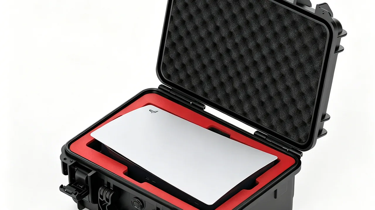
When equipment arrives damaged, the shell is rarely the culprit. The shell keeps water and dust out; what decides how many g the payload sees during the last twenty milliseconds of a drop is the liner: its material family, its density, its thickness, and how faithfully the cavity matches the item. JUNZHIJIA works to one principle on every liner programme: a foam insert is not packing filler but an engineered energy-management component, profiled from measured geometry, specified from a static-stress window, and verified against cushion curve data.
The chain runs from digitising the payload and locating its centre of gravity, through material and density selection, cushion curve checking, cavity nesting, process selection between CNC cutting, die cutting and compression moulding, tooling amortisation, trial fitting, tolerance convergence and revision freeze, to production consistency and acceptance. Skip the calculation at any link and the drop test finds it: an oversized cavity lets the item strike the interior twice, one density step too soft lets the foam bottom out, ten millimetres short on thickness roughly doubles peak acceleration. This article walks the chain in engineering order.
Table of Contents
- Item Survey and Measurement Baseline
- Service Risk Inputs: Drop Height, Frequency and Transport Mode
- Foam Material Families: EPE, EVA, PU, IXPE and EPP Compared
- Selecting Density and Hardness
- Static Stress and Cushion Curves: From Data to Thickness
- Cavity Layout and Handling Ergonomics
- Forming Processes Compared: CNC Cutting, Die Cutting and Compression Moulding
- Tooling Cost, Minimum Order Quantity and the Break-Even Point
- Multi-Layer Construction: Hard Base, Soft Face and Zoned Density
- Tolerances, Fit and Trial-Fit Validation
- Revision Control and Engineering Change
- Acceptance Criteria and Shipment Documentation
- Frequently Asked Questions FAQ
- Conclusion and Related Reading
Item Survey and Measurement Baseline
The first step is not drawing a cavity but building a traceable measurement baseline. The payload is an entity with tolerances, protrusions and vulnerable zones, not the outline drawing in the brochure. Brochure drawings give length, width and height and omit connector bosses, knobs, lens front groups, heat sink fins and cable exits, which are precisely the features that dictate cavity geometry.
Four data classes are required. The envelope is the outer boundary including every non-removable protrusion. Functional surface positions, such as displays, optical windows and connector faces, must be left clear or protected by a soft facing layer. Mass and centre of gravity matter because the further the centre of gravity sits from the geometric centre, the larger the overturning moment during a drop, so the heavy side needs more support area. The contact map separates zones that tolerate foam pressure from zones restrainable only by adjacent structure.
| Survey item | Tool | Accuracy | Effect on liner design |
|---|---|---|---|
| --- | --- | --- | --- |
| Envelope dimensions | Digital calliper / CMM | ±0.2 mm | Sets cavity outline and case interior |
| Curved surfaces | 3D scanning / cast impression | ±0.5 mm | Decides contoured fit or clearance |
| Mass and centre of gravity | Bench scale + pivot method | ±2% / ±5 mm | Sets support split and ballast |
| Vulnerable features | Visual review + load path study | Qualitative | Sets exclusion zones and thickness |
| Service temperature range | Chamber logging / field record | ±2 °C | Sets material class and creep allowance |
Tool choice follows the accuracy needed: callipers for envelopes, laser or structured-light scanning for curved shapes, with soft parts such as cables held in a repeatable pose so repeated scans agree.
The captured data becomes a profiling input sheet recording the equipment serial, accessory list and shipped spares. Every later revision returns to that sheet rather than editing an old drawing; a large share of production-phase fit complaints traces back to a missing or mixed-version input sheet.
Service Risk Inputs: Drop Height, Frequency and Transport Mode
Cushioning capacity must match real risk. The same instrument carried to a vehicle and shipped as less-than-truckload freight across a province sees entirely different shock spectra, and one specification either overbuilds volume and mass or underbuilds protection.
The first risk input is drop height. Practice segments by mass: hand-carried items under 10 kg are checked at 800 to 1000 mm, 10 to 25 kg at 600 to 800 mm, 25 to 50 kg at 450 to 600 mm, and heavier units by tip-over rather than free fall. The second is orientation probability: corner drops generate higher peak acceleration than face drops because energy concentrates on a smaller contact patch, so corners need more usable stroke. The third is transport mode. Road freight random vibration concentrates between 3 and 50 Hz, air freight adds low pressure and low temperature, sea freight adds humidity, salt and long-duration stacking load.
| Service scenario | Drop height | Fragility G | Liner design bias |
|---|---|---|---|
| --- | --- | --- | --- |
| Hand-carried inspection | 800 mm | 40–60 | Medium density, weight conscious |
| Precision instrument linehaul | 600 mm | 25–40 | Thicker section, longer stroke |
| Heavy load over 25 kg | 450 mm | 40–80 | High density, zoned load paths |
| Air freight, low pressure | 600 mm | 30–50 | Rebound plus expansion allowance |
| Long-term stacked storage | Not applicable | Creep governed | High compression resistance |
Transport test standards turn these inputs into executable checks. GB/T 4857 covers drop, stacking and vibration methods; ASTM D4169 provides a programme graded by distribution environment; the ISTA series sets drop heights and sequences by parcel type. A custom liner should complete at least one drop sequence during sampling, with measured acceleration confirming the calculation rather than field breakage triggering a density change.
Fragility, the maximum acceleration the payload tolerates, belongs to the equipment; the liner's job is to hold transmitted acceleration below it. The same reasoning is developed further in Cushion Liner Cases.
Foam Material Families: EPE, EVA, PU, IXPE and EPP Compared
Foam is not one material but a family whose blowing processes differ widely. Picking the wrong family cannot be repaired later by tuning density.
EPE, expanded polyethylene, is a non-crosslinked closed-cell foam: light, resilient, low cost, with relatively high compression set, suited to short-cycle use. EVA, ethylene-vinyl acetate foam, is a closed-cell elastomer with a wide hardness range and good hot-press formability, suited to contoured cavities. PU flexible foam is open cell and soft with good energy absorption, but it absorbs moisture and creeps, so it serves as a facing layer. IXPE and XPE, irradiation and chemically crosslinked polyethylene, have fine uniform cells with better rebound and weathering than EPE. EPP, expanded polypropylene bead foam, is stiff and survives repeated impact, used for corner reinforcement.
| Material | Density kg/m³ | Cell structure | Rebound | Compression set | Typical use |
|---|---|---|---|---|---|
| --- | --- | --- | --- | --- | --- |
| EPE | 18–40 | Closed, non-crosslinked | Good | Relatively high | General transfer |
| EVA | 50–250 | Closed, crosslinked | Excellent | Low | Contoured cavities |
| PU flexible | 20–80 | Open | Excellent | Moderate to high | Facing layers |
| IXPE | 33–200 | Closed, irradiation crosslinked | Excellent | Low | High precision |
| XPE | 30–150 | Closed, chemically crosslinked | Good | Fairly low | Mid to high tier |
| EPP | 20–100 | Closed, bead moulded | Excellent | Very low | Corner supports |
The temperature window deserves equal scrutiny. EVA stiffens markedly at low temperature and its cushion curve shifts upward; PU hydrolyses in hot humid service; IXPE has the widest thermal and weathering window at the highest cost. Where a case is opened outdoors in cold conditions, low-temperature stiffening must enter the calculation, as covered in Inner Cushioning for Outdoor Cases.
Common engineering combinations are EVA or IXPE for the primary load path, PU or low-density EVA as the facing, and EPP or high-density EVA at corners and heavy points. The trade-off between the two most common families is set out in EPE vs EVA Foam Toolbox Liners.
Selecting Density and Hardness
Within one family, density changes mechanical behaviour by multiples, and it is the primary control variable in cushioning design; hardness, reported in Shore C or Asker C, is its companion indicator and the practical tool for incoming inspection.
Density governs compressive strength, energy absorption and cost. Low-density foam has low compressive strength, so a small static load already pushes it into the middle of its useful stroke, which suits light payloads. High-density foam resists crush under larger static load and suits heavy payloads, but paired with a light item it is too stiff and passes shock straight through, raising peak acceleration. The working point has to sit in the lowest region of the cushion curve.
| Payload mass | Primary material | Density kg/m³ | Hardness Asker C | Cavity wall |
|---|---|---|---|---|
| --- | --- | --- | --- | --- |
| Under 1 kg | EVA / IXPE | 50–70 | 25–35 | 10–15 mm |
| 1–5 kg | EVA / IXPE | 60–90 | 30–45 | 15–25 mm |
| 5–15 kg | EVA | 90–130 | 45–60 | 20–35 mm |
| 15–30 kg | EVA / EPP hybrid | 130–180 | 55–70 | 30–45 mm |
| Over 30 kg | EPP plus EVA | 150–220 | 60–75 | 40–60 mm |
Hardness earns its keep in production: density can be back-calculated from mass, but that is awkward on shaped parts, whereas a durometer reads in seconds. Incoming inspection samples three points per batch and rejects deviation beyond ±5 points. Readings are temperature sensitive, so the test room is held at 23 ± 2 °C with specimens at least 10 mm thick, otherwise results skew low.
Compression set is frequently ignored. Under sustained load or repeated impact, thickness is lost irreversibly and an interference fit becomes a clearance fit, so the payload starts to move. Practice requires the primary load path material to show compression set no greater than 10% under 70 °C, 22 hours, 50% compression, and no greater than 5% under long-term stacking.
Static Stress and Cushion Curves: From Data to Thickness
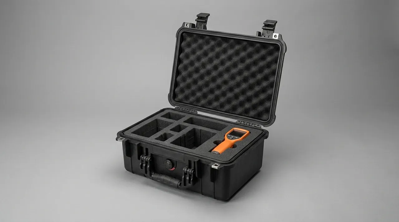
The quantitative core of cushioning design is the peak acceleration versus static stress curve, shortened to the cushion curve. The horizontal axis carries static stress, payload weight divided by load-bearing area; the vertical axis carries the maximum acceleration transmitted to the payload, in multiples of g, for a given material, density and thickness.
The calculation runs in three steps. First, static stress: divide payload weight W in newtons by the projected load-bearing area A in square centimetres to obtain sigma in kilopascals. Load-bearing area means the projected area actually pressing on foam, not the cavity footprint; the conservative method counts the bottom only. Second, read the curve for the chosen material, density and thickness to find G. Third, verify: if G exceeds payload fragility, increase bearing area to lower sigma, or increase thickness, repeating until G sits below fragility with at least 20% margin.
| Parameter | Expression | Meaning | Common error |
|---|---|---|---|
| --- | --- | --- | --- |
| Static stress sigma | W / A | Weight over bearing area | Counting side walls as bearing |
| Energy per volume | Curve value times thickness | Sets total stroke | Ignoring thickness effect |
| Verification rule | G at or below 0.8 times fragility | 20% margin retained | No margin, scatter then fails |
| Temperature correction | Curve shifted by temperature | Cold stiffens, heat softens | Room curve applied everywhere |
| Creep correction | Thickness times (1 minus set) | Effective service thickness | Initial thickness only |
Thickness is routinely underrated. Adding thickness lengthens the stroke and lowers the whole curve, because strain rate per unit thickness falls, but past a certain point the gain decays quickly while volume and cost keep climbing. The converging method computes the minimum thickness that satisfies G, then adds 10 to 15% for creep and manufacturing tolerance.
Temperature matters equally. EVA can stiffen by more than 30% at minus 20 °C, shifting the curve upward, so a solution verified at room temperature may fail in the cold. Payloads opened in alpine or desert conditions should be re-verified on the extreme-temperature curve or moved to IXPE.
Cavity Layout and Handling Ergonomics
A cavity that holds the item but will not release it is a failed liner. Handling ergonomics is the step most often squeezed in custom insert work, and it is what operators experience daily.
Finger clearance is the first constraint: items lifted by pinching need a recess at least 18 mm wide and 25 mm deep, growing to 25 mm by 35 mm with gloves. Items over 2 kg cannot be pinched and need a lift strap, either a webbing loop or a moulded foam tongue, so the operator pulls with the whole hand. The strap root must tie into the main structure, not merely bond to the cavity surface.
| Ergonomic factor | Recommended value | Condition | Failure symptom |
|---|---|---|---|
| --- | --- | --- | --- |
| Finger recess width | At least 18 mm, gloved 25 mm | Pinch-lifted items | Cannot remove, foam torn |
| Lift strap free length | At least 40 mm | Mass over 2 kg | Fingers cannot pass through |
| Cavity draft angle | 5 to 8 degrees | Compression moulded parts | Tearing on demould |
| Wall between cavities | At least 8 mm, heavy duty 12 mm | All cavities | Partition cracks in transit |
| Centre of gravity offset | Within 15% of cavity long side | Multi-item cavities | Case tilts when carried |
Layout also encodes removal order: high-frequency items belong on the top layer or nearest the opening, low-frequency spares at the bottom. Where heavy and light items share a case, the heavy one sits near the centre and toward the handle. Multiple identical items in a row each need an independent removal path; nesting that forces item A out before item B is acceptable only where procedure requires it.
The lid pad is not optional. It presses the payload from above once the lid closes and removes vertical free play. Lid pad thickness is typically 8 to 20 mm with 20 to 30% compression: too tight and the lid will not latch, too loose and it limits nothing. Bottom cavity and lid pad should clamp, not jam.
Forming Processes Compared: CNC Cutting, Die Cutting and Compression Moulding
Process choice sets cavity accuracy, unit cost, batch flexibility and revision speed.
CNC cutting follows a programmed path with a router bit, an oscillating knife or a hot wire: router bits suit EVA and EPP but generate dust, oscillating knives suit EPE and softer grades, hot wires seal the kerf at lower accuracy. CNC needs no tooling and revision means a new program, which suits sampling and small runs; its weakness is long cycle time and material yield that depends on nesting.
Die cutting punches cavities in one stroke with a steel rule die. Die cost ranges from a few thousand to tens of thousands depending on complexity. It is fast, consistent and nests efficiently above roughly a thousand pieces; revision means a new die, and deep irregular cavities are limited by punch depth.
Compression moulding heats sheet and presses it between matched tools to produce a contoured cavity with a dense skin and the best appearance. Tooling cost and lead time are highest, unit cost at volume lowest. Water jet cutting handles hard or thick stock accurately at high equipment cost, leaving edges that need drying.
| Process | Batch range | Tolerance | Tooling investment | Sampling lead | Main limitation |
|---|---|---|---|---|---|
| --- | --- | --- | --- | --- | --- |
| CNC routing | 1–500 pieces | ±0.5 mm | None | 2–5 days | Long cycle time, dust |
| Oscillating knife | 1–300 pieces | ±1.0 mm | None | 2–4 days | Fair verticality deep |
| Die cutting | Over 500 pieces | ±0.5 mm | Thousands upward | 7–15 days | High revision cost |
| Compression moulding | Over 2000 pieces | ±0.3 mm | Tens of thousands | 20–35 days | Long lead, EVA only |
| Water jet | 1–200 pieces | ±0.3 mm | None | 3–7 days | Edges need drying |

Routes are rarely exclusive. A common path is CNC for sampling and small runs, then a die once volume justifies it, with hot-press finishing on premium appearance parts. Programmes expecting several revisions should stay on CNC early to keep iteration cheap. EVA Foam Insert Custom Process maps the milestones.
Tooling Cost, Minimum Order Quantity and the Break-Even Point
Whether to cut a die is an amortisation problem. Let T be one-time tooling, p1 the die-cut unit cost and p2 the CNC unit cost, with p2 higher; the break-even quantity is T divided by the difference. Below it CNC is cheaper, above it tooling pays back.
Take a representative case: a mid-complexity die at 8000 currency units, die-cut processing at 4 per piece, CNC at 14 per piece. The break-even quantity is 800 pieces. Only after cumulative output passes 800 does the die start saving money; a programme consuming 300 pieces a year wastes money by tooling up.
| Batch band | Process | Unit cost trend | Decision focus |
|---|---|---|---|
| --- | --- | --- | --- |
| 1–50 pieces | CNC | High, no sunk cost | Validate cavity before tooling |
| 50–500 pieces | CNC mainly | Moderate | Improve nesting to cut loss |
| 500–2000 pieces | Die cutting | Falls clearly | Freeze geometry first |
| 2000–10000 pieces | Die or compression | Lowest | Optimise material yield |
| Over 10000 pieces | Compression moulding | Lowest, best finish | Include tool life |
Revision risk belongs in the same calculation: once a die exists, a payload change writes it off in full, so while a product is still changing, paying more per piece on CNC buys freedom. Where a model has been stable for three years, tooling return is predictable.
Minimum order quantity is rarely a process limit; it is a material and scheduling limit. Die shops set a minimum run to cover setup scrap, and sheet suppliers sell by full sheet or roll. Any enquiry should confirm three numbers at once: tooling charge, unit price, and minimum sheet quantity. For programmes needing only a few dozen sets, a pragmatic bridge is Pick-and-Pluck Foam Cases until volume justifies tooling.
Multi-Layer Construction: Hard Base, Soft Face and Zoned Density
A single-density monolayer rarely satisfies both supporting a heavy item and protecting a delicate face. Multi-layer construction assigns each layer a distinct function.
The classic three-layer build puts a high-density base under the static load to provide stroke, a medium-density cavity layer that locates and supports the payload, and a low-density facing protecting finished surfaces, plus a lid pad for vertical restraint. Layers are bonded with water-based or hot-melt adhesive; solvent adhesives swell cells and should be avoided.
| Layer | Function | Density | Thickness | Material |
|---|---|---|---|---|
| --- | --- | --- | --- | --- |
| Base support | Carries load, provides stroke | 130–200 kg/m³ | 10–20 mm | EVA / EPP |
| Middle cavity | Location, lateral support | 60–120 kg/m³ | Per payload | EVA / IXPE |
| Facing | Protects surfaces | 30–60 kg/m³ | 3–8 mm | PU / IXPE |
| Lid pad | Vertical restraint | 30–50 kg/m³ | 8–20 mm | EVA / PU |
| Corner reinforcement | Resists corner drops | 150–220 kg/m³ | Local 15–30 mm | EPP |
Zoned density is the advanced form: within one layer, blocks of different density are butted together according to local vulnerability. An instrument with an optical window might use low-density IXPE at the lens, medium EVA under the metal body, and high-density EPP at the base connector. Joints must be staggered off the main load path so no seam sits on the primary shock route.
The cost of layering is added operations and accumulated thickness: each layer raises overall height and case volume, so composite thickness must enter case selection at the start. Bond reliability also needs checking: a hand-peel test that must not delaminate belongs in first-article inspection.
Tolerances, Fit and Trial-Fit Validation
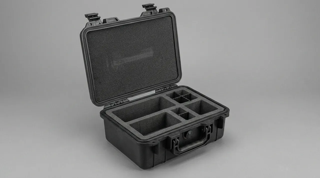
Foam is compliant, so its tolerance system differs from metal: cut foam rebounds, the kerf contracts, and the part moves with ambient conditions, so cavity dimensions are never copied directly from measured payload dimensions. An interference allowance is added instead.
The allowance depends on process and material. CNC routed EVA cavities take 0.5 to 1.0 mm interference per side, meaning the nominal cavity is 1 to 2 mm smaller than the item and clamping comes from foam compression. Die-cut parts rebound more and can take 1.0 to 1.5 mm. Compression moulded parts contour closely and need only 0.3 to 0.8 mm. Too much interference makes loading hard and tears foam on removal; too little loses clamping and lets the item rub in transit.
| Tolerance item | Typical value | Influencing factors | Check method |
|---|---|---|---|
| --- | --- | --- | --- |
| Cavity interference per side | 0.5–1.5 mm | Process, hardness | Trial fit plus feeler gauge |
| Cavity position | ±1.0 mm | Nesting accuracy, datum | CMM or template |
| Cavity depth | +0 / −1.0 mm | Tool depth, rebound | Depth gauge, three points |
| Overall thickness | ±1.5 mm | Lamination, adhesive | Thickness gauge, five points |
| Insertion force | 20–60 N | Interference, friction | Force gauge |
Trial fitting runs at least three rounds: the static round seats the payload and checks that every feature reaches position without forced squeeze or bridging; the closed-lid round checks lid pad compression, latch engagement and shell bulge; the dynamic round runs the specified drops, then checks displacement, tearing and permanent set.
Criteria must be executable rather than subjective: peak insertion force not above 60 N, strap pull force not above 40 N, payload displacement after drop not above 2 mm. These serve both sample approval and production audit, and can be aligned with Custom Case Prototyping Timeline.
Revision Control and Engineering Change
The commonest quality incident in custom liners is not a design error but version drift: the payload is revised, the drawing is not, the line builds three thousand sets to the old revision, and all of it is scrap. Revision control turns a correct design into a consistently correct product.
A minimal system has four elements: a drawing numbering rule, a layer naming convention, a change log, and retained samples. Drawing numbers carry project code, liner level, revision and date; layer names separate outline, cavity, clearance and annotation so later edits do not disturb unrelated geometry; the change log records reason, affected scope and stock impact.
Sample approval is the freeze point. The customer confirms in writing against an approval sample covering cavity match, removal smoothness, density and appearance, and at least two samples are retained: one sealed as the production standard, one filed with documents. The first production article is compared item by item for critical dimensions, overall thickness and hardness.
Engineering change follows a defined sequence: the originator states the change, the designer assesses impact on tooling and inventory, both parties agree the effective batch, and the line switches at that batch. Where a die exists and the change touches cavity dimensions, the note must state whether it is reworked, scrapped, or run to end of life. Production consistency is maintained by audit rather than full inspection, sampling hardness, critical dimensions and appearance per batch at AQL general inspection level II, with a material grade lock forbidding unannounced changes to the blowing compound.
Acceptance Criteria and Shipment Documentation
Acceptance converts design intent into decidable clauses that are measurable and repeatable, never phrased as no visible defect.
Four classes are usual. Dimensions and fit cover critical cavity dimensions, overall thickness, clearance to the case interior and insertion force. Material properties cover density by mass and volume, hardness at three points, and compression set by sample or certificate. Functional verification covers drop testing with no displacement, damage or permanent set beyond 10%. Appearance and compliance cover odour, colour consistency, dust shedding, and where required RoHS or REACH declarations.
| Acceptance item | Method | Acceptance rule | Sampling |
|---|---|---|---|
| --- | --- | --- | --- |
| Critical dimensions | Calliper / CMM | Within drawing tolerance | 5 per batch |
| Density | Mass and volume | Nominal ±8% | 3 per batch |
| Hardness | Asker C durometer | Nominal ±5 points | 3 per batch, 3 points |
| Insertion force | Force gauge | 20–60 N | 5 per batch |
| Drop verification | GB/T 4857 or ASTM D4169 | No displacement, no damage | Once per model per year |
| Appearance | Visual at 300 lx | No tearing, no marked shade | AQL level II |
Shipment documentation is part of delivery quality. A complete set includes the insert assembly drawing with cavity numbering and item list, a material statement covering type, density, hardness and temperature range, maintenance guidance covering cleaning, replacement interval and prohibited solvents, and a change log summary. Long-supply programmes should state a recommended spares stock: liners are consumables, and a break in spares supply grounds the whole case. Grading follows Custom Case Acceptance and AQL, assessing liner and shell as one system.
Frequently Asked Questions FAQ
Q: What is the first step in a custom foam insert project, and can the cavity simply be drawn from the equipment outline drawing?
A: No. The first step is building a profiling baseline that captures the envelope including every non-removable protrusion, the positions of functional surfaces, mass and centre of gravity, the permitted and prohibited contact zones, and the service temperature range. Outline drawings give overall dimensions but omit connector bosses, lens front groups, heat sink fins and cable exits, which are exactly the features that decide cavity geometry, so a cavity traced from them usually interferes or bridges on first trial fit. Once surveyed, the data becomes an archived input sheet that every later revision starts from. For complex curved payloads, three-dimensional scanning with reverse modelling to within 0.5 mm is more reliable and more reusable than hand tracing, provided soft parts such as cables are held in a repeatable pose so that two scans agree. Record also whether accessories ship fitted or separately, because a cavity sized for a bare unit will not accept one with a lens hood or a battery pack attached, and separate cavities are cheaper to revise later.
Q: How do I decide how thick the foam should be, and is thicker always better?
A: Thickness comes from cushion curve verification, not from a rule of thumb, and thicker is not automatically better. Compute static stress as payload weight divided by the projected bearing area, then read the maximum transmitted acceleration from the curve for the chosen material, density and thickness. If that value exceeds payload fragility, increase bearing area to lower static stress or add thickness, repeating until the result sits below fragility with at least twenty percent margin. Added thickness does lower the curve because strain rate per unit thickness falls, but the benefit decays quickly beyond a certain point while volume, weight and cost keep rising. Calculate the minimum thickness that satisfies the target, then add ten to fifteen percent for creep and manufacturing tolerance. Remember that cold stiffens EVA and shifts the curve upward, so alpine service demands re-verification or a move to IXPE. Where no published fragility figure exists, start conservatively at 30 g for optical instruments, 50 g for general electronics and 80 g for steel fabrications, then refine by instrumented drop testing.
Q: How should I choose between CNC cutting, die cutting and compression moulding, and when is tooling worth it?
A: The decision turns on a break-even quantity. Let T be one-time tooling cost, p1 the die-cut unit processing cost and p2 the CNC unit processing cost, with p2 higher; the break-even quantity is T divided by the difference between p2 and p1. Below that quantity CNC costs less, above it tooling pays back. A die at eight thousand currency units with die-cut processing at four and CNC at fourteen gives a break-even of eight hundred pieces. Beyond the arithmetic, weigh revision risk: while the payload is still changing, a scrapped die is a total loss, so paying more per piece on CNC buys valuable freedom, whereas a model stable for three years or more gives predictable tooling return. The common route is CNC for sampling and small runs, then a die once geometry freezes and volume justifies it, with hot-press finishing added for premium appearance parts. Processing route also shapes appearance: routed faces show tool marks, die-cut edges are square and clean, and moulded cavities carry a dense skin that resists soiling and cleans easily in field service.
Q: How much interference should a cavity have, and what happens if it is too tight or too loose?
A: Interference depends on process and material. CNC routed EVA cavities take 0.5 to 1.0 mm per side, die-cut parts rebound more and can take 1.0 to 1.5 mm, and compression moulded parts contour closely and need only 0.3 to 0.8 mm. Too much interference makes loading difficult and tears the foam on removal, and in the worst case pulls the lift strap off. Too little loses clamping, so the payload shifts in transit, abrades, and can strike the interior twice. Fit must be judged by numbers, not feel: peak insertion force not above 60 N, strap pull force not above 40 N, and payload displacement relative to the cavity after drop testing not above 2 mm. Keep cavity position within 1.0 mm, depth shortfall within 1.0 mm, and the wall between adjacent cavities at least 8 mm, or 12 mm for heavy loads. Re-check interference after any process change, because switching from routing to die cutting alters rebound and edge squareness, and a carried-over value usually gives a loose fit or a torn cavity.
Q: Why do two batches of foam with the same nominal density feel different once installed?
A: Density is only one control variable. Blowing compound grade, expansion ratio, cell structure, crosslink density and maturation time all shift real mechanical behaviour, and two foams at identical nominal density can differ by more than twenty percent on the cushion curve, which is exactly what the hand feels during installation. Control starts in the purchase contract with a material grade lock forbidding unannounced changes to the blowing compound. Incoming inspection then measures hardness at three points per batch under controlled conditions of 23 plus or minus 2 degrees Celsius with specimens at least 10 mm thick, rejecting deviation beyond five points, and back-calculates density from mass and volume within eight percent. For long-running supply, require a compression set and cushion curve report every six months so batch-to-batch consistency stays traceable rather than assumed, and keep sealed reference samples for direct comparison whenever a new batch arrives on the line. Compression set, rebound rate and cell structure should appear on every material certificate, because density alone cannot distinguish a well-crosslinked grade from a filler-loaded one that behaves differently under repeated impact.
Q: What is the point of a multi-layer liner, and are more layers always better?
A: Multi-layer construction resolves the conflict between supporting a heavy payload and protecting a delicate surface. A typical three-layer build uses a high-density base of 130 to 200 kilograms per cubic metre and ten to twenty millimetres to carry static load and provide stroke, a medium-density cavity layer of 60 to 120 for location and lateral support, a low-density facing of 30 to 60 and three to eight millimetres to protect finished surfaces, plus a lid pad for vertical restraint. Zoned density extends the idea, with low-density IXPE at a lens, medium EVA under the metal body and high-density EPP at a base connector. More layers are not automatically better: each adds height and therefore case volume, and every bond line is a potential delamination site. Composite thickness belongs in case selection from the start, bonding should use water-based or hot-melt adhesive rather than solvent, and a hand-peel test that must not delaminate belongs in first-article inspection. Zoning also improves repairability, since a damaged high-density corner block can be replaced without scrapping the whole liner, which matters on large cases where the liner is a significant share of total cost.
Q: How long does an insert last, and how can I tell that it has failed?
A: An insert is a consumable, and service life depends on duty cycle and material. Four observable signals indicate failure. First, thickness loss: visible compression at the cavity floor or lid pad with slow rebound, measuring more than ten percent below the original thickness. Second, loss of clamp: the payload moves when the case is gently shaken, or insertion force drops below twenty newtons. Third, structural damage: torn or crumbling partition walls, or a lift strap debonded at the root. Fourth, material ageing: a tacky, powdering or odorous surface, which means the polymer is degrading. EVA liners in ordinary rotation are assessed every two to three years, high-intensity daily use every year, and cases kept under long-term stacking need periodic checks even when unused, because constant compression produces creep. Replacement liners must be ordered to the current drawing revision. Replacement decisions should follow measurement rather than the calendar alone: log insertion force and cavity depth at each service inspection, and replace when the trend crosses the threshold even if surface appearance still looks acceptable.
Q: How should drawing revisions be managed, and what happens to existing liners when the payload changes?
A: A minimal revision system has four elements: a drawing numbering rule, a layer naming convention, a change log, and retained samples. Drawing numbers carry project code, liner level, revision and date; layer names separate outline, cavity, clearance and annotation so local edits do not disturb unrelated geometry. Sample approval is the freeze point: after written confirmation, seal at least two approval samples, one as the production comparison standard and one filed with project documents, and compare the first production article item by item for critical dimensions, overall thickness and hardness. After a payload change, run an engineering change: the originator states the change, the designer assesses impact on tooling, dies and inventory, both parties agree the effective batch, and the line switches at that batch. Where a die exists, the note must state whether it is reworked, scrapped, or run to end of life. Obsolete stock should be quarantined.
Conclusion and Related Reading
Treat liner specification as calculated, verified engineering, and JUNZHIJIA can take a programme from survey through sampling, tooling and production with full OEM and ODM support.
Related Reading