

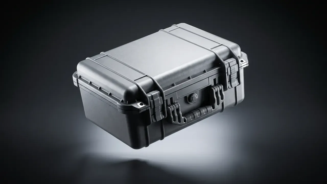
Quick answer: This EMI Shielding Case run built a 520 × 380 × 210 mm cavity rated at 60 dB from 400 MHz to 1 GHz across a minus 40 to 71 °C swing. Six weeks showed the outcome hinges on gasket compression, plate bonding and a single ground point, not coating thickness.
Table of contents
- Where the Brief Started: Three Duty Cycles in One Test Bay
- Assembly Order: Gasket, Interface Plate, Ground Stud
- Operator Actions: Open, Plug, Reset
- Four Failures That Sent the Sample Back
- Accepting the Sample and Writing It Into the Drawing
- FAQ
1. Where the Brief Started: Three Duty Cycles in One Test Bay
The customer integrates airborne test equipment. The bay sits outdoors, bakes by day, soaks in dew at night and moves three times a year. They sent only a cabinet outline with three cable exits.
An EMI Shielding Case is designed from a duty-cycle table, not from an outline. We split the year into transit, powered operation, relocation.
| Duty cycle | Conditions | Configuration |
|---|---|---|
| Transit | Stacked two high, cart vibration, 55 °C | 4.5 mm wall, top ribs, corner guards |
| Powered | Three cable runs, 8 h continuous | End interface plate, filtered connectors, one ground stud |
| Relocation | Two-person lift, 0.8 m drop, rain | Moulded handles, two latches, tongue-and-groove gasket joint |
The table fixes logic only; the numbers wait for the retest. So the first decision froze every opening before coating. Drilling after coating is the most common self-inflicted delay.
2. Assembly Order: Gasket, Interface Plate, Ground Stud
Assembly order caused an argument on the floor. They mount the interface plate first because routing cable is easier; in practice a plate bolted down first pushes the lid gasket aside and the lid never compresses it evenly. The order that works: gasket in the groove, lid closed once, plate last.
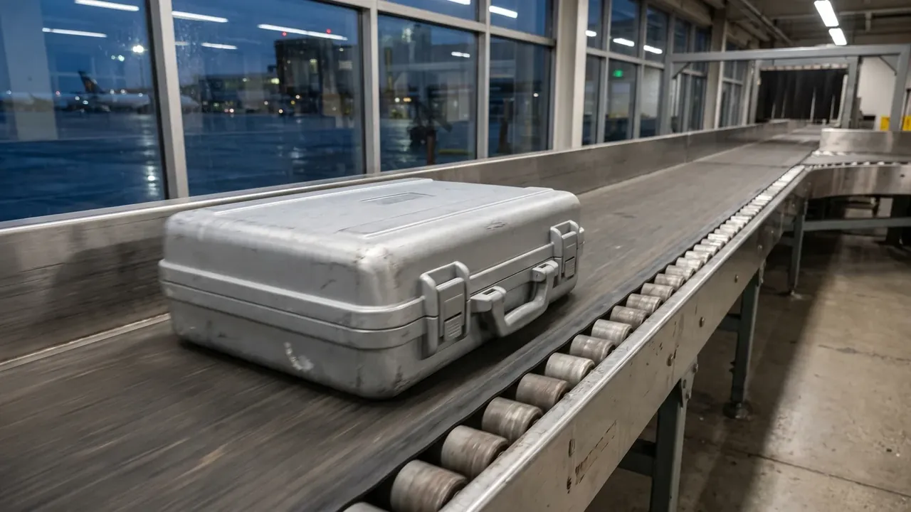
Three numbers matter at the gasket: groove depth, compression, rebound. A 3 mm groove with a 4 mm gasket gives about 25 percent compression, inside the stable band for conductive silicone; too little makes contact intermittent, too much takes a permanent set. This EMI Shielding Case sample held 2.8 to 3.2 mm, checked with a feeler gauge at each corner.
The interface plate carries six connectors, two power and four signal. Power positions take filtered connectors, signal positions shielded circular connectors bonded through a conductive gasket. Screws alone do not bond a plate to a wall, so spacing stayed under 80 mm with a gasket strip between; otherwise the span between two screws is a long slot. Grounding is the third point: one stud, 30 mm below the plate, M6, 1.8 N·m, braided copper to the floor bar; multiple points form loops and lift the low-frequency noise floor.
3. Operator Actions: Open, Plug, Reset
On week five we moved the case on site and had three operators run ten cycles each, noting hesitations.
- Lid: press both latches with two fingers; it must swing past 60 degrees and not stall halfway.
- Cable: the plug should seat one-handed, with insertion force under 30 N.
- Reset: check the gasket sits in the groove, then close until both latches click.
- Stow: coil the cable on the side hooks rated 2 kg, never over the handle.
Any action that hesitated twice in ten tries went back to the drawing.
4. Four Failures That Sent the Sample Back
Before the retest we stripped the sample. Three of four failures came from process handover, one from design.
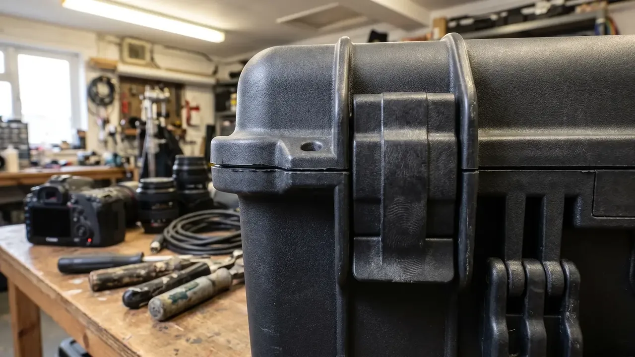
First, coating covered the side wall of the seal groove, and contact resistance rose from 8 mΩ to 40 mΩ. Second, burrs on an interface cut were never removed, the gasket took a dent, and that band lost 9 dB. Third, the ground stud landed on the overlap of two wall panels, right on the seam. The fourth was design: a tongue depth of 2 mm made operators align the lid twice.
The first two cost one rework; the third meant re-cutting and re-coating, about four days.
5. Accepting the Sample and Writing It Into the Drawing
The retest ran in a third-party chamber: whole case, all connectors fitted, latches closed as in use. Nine points from 400 MHz to 1 GHz gave a 62 dB minimum near 860 MHz; the 30 to 400 MHz band reached 38 dB, the ceiling of a coating approach.
| Item | Criterion | Measured |
|---|---|---|
| Shielding effectiveness | 60 dB+, 400 MHz to 1 GHz | 62 dB minimum |
| Gasket contact resistance | 10 mΩ or less per point | 6 to 8 mΩ |
| Salt spray | 96 h, no blistering | pass |
| Total weight | 10 kg or less | 9.6 kg |
After acceptance we compressed the tables into one page of drawing notes. An EMI Shielding Case drawing listing only size and material drifts by the second batch, since the numbers that decide performance never appear on an outline.
Conclusion
Twelve samples shipped at the end of the run, and the customer pinned the acceptance sheet beside the assembly bench. Across six weeks, the time saved came from one habit: before each step, ask whether it breaks the continuity built by the step before. An EMI Shielding Case is not measured into performance; it is sequenced.
This article discusses only the container (case body) side of specifications and design intent, and does not cover any handling, loading or use of the contents.
Related Reading
- How shielding, grounding and sealing work together
- Writing the specification sheet for a shielded case
- Road case configurations for relocation work
- Case configurations for medical equipment
Related Products
- 8 Series — Gun Cases; Military Equipment Cases; Camera Equipment Cases; Drone Cases; Watch Cases; Knife Cases; First Aid Cases; Electronics Equipment Cases
- WL8-2812 PP Gun Case — model WL8-2812
- All protective cases and toolboxes: 7 series, 158 models