

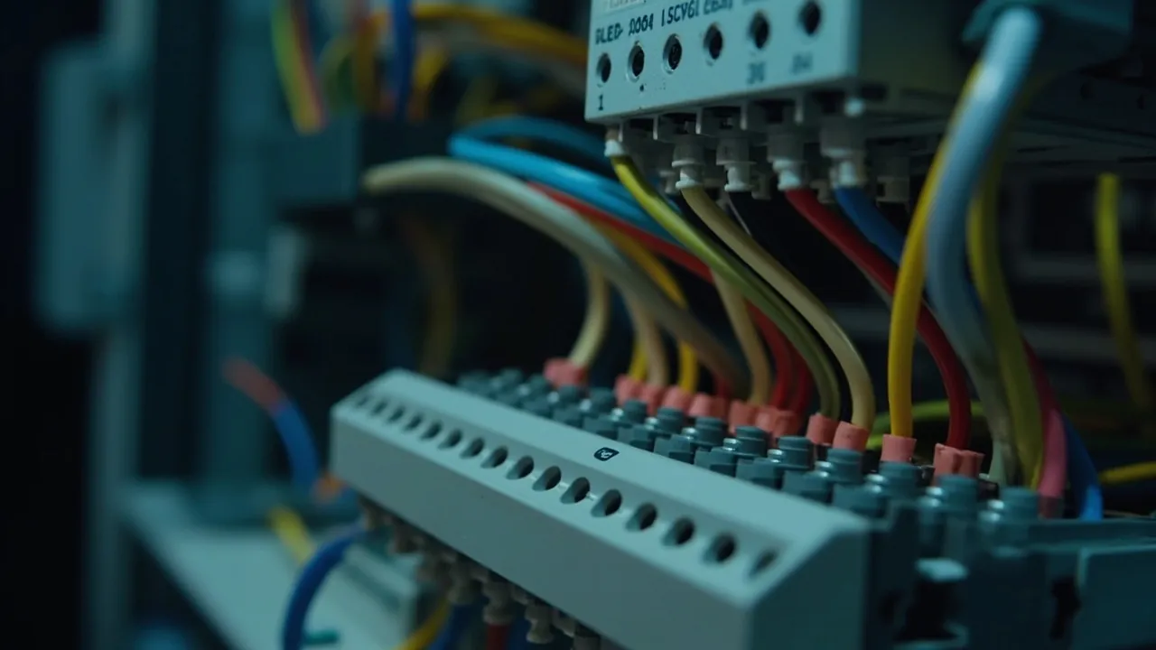
Once the enclosure arrives, half the remaining work sits in the sealing structure and half inside the shell. Plenty of water ingress investigations find no sealing defect at all and end up locating the cause inside a crowded harness: a conductor trapped across the lid joint, a gland pulled out of true by the weight of its own cable run, or water walking in along a cable. None of that has anything to do with the rating printed on the box. It is purely installation practice, and it decides whether the rating is actually held.
This article follows the real sequence. Calculate the space first, choose the cable, then deal with entry direction, hole layout, bend radius, terminal arrangement, screening and earthing, tying and labelling, and thermal management, closing with a checklist ready for use. Wiring practice references IEC 60364 and GB 50303, ingress classification follows IEC 60529 adopted as GB/T 4208-2017, and the clearances quoted are widely accepted field values.
Contents
- Wiring Governs the Other Half of Protection
- Calculate the Space First: Volume and the Forty Percent Rule
- Choosing Cable for Outdoors
- Entry Direction and Drip Loops
- Rules for Laying Out Holes
- Bend Radius and Spare Length
- Terminals, Rails and Separating Power from Signal
- Screening, Earthing and Bonding
- Fixing, Tying and Labelling
- Thermal Management Around Heat Sources
- Eight Wiring Errors
- Completion Checklist
- Frequently Asked Questions (FAQ)
- Closing Notes and Further Reading
Wiring Governs the Other Half of Protection
One plain fact underpins everything here: IP type testing is carried out on an empty box. The sample is either empty or holds only a specified dummy load. On site the enclosure will receive a dozen or more cables, dozens of terminals, contactors and power supplies, and those additions change three things, each of them load-bearing for the sealing system.
First, they change the compression state. If a harness is trapped across the lid joint, it acts like a piano wire laid along the sealing line. Clamping force rides over it and channels open on either side. A spray test finds that instantly, but without testing it usually takes months to surface.
Second, they change the stress distribution. When ties gather every conductor into one bundle anchored at a single point, repeated thermal cycling transfers that pull onto terminals, and sustained tension on a screw terminal can loosen it until it heats.
Third, they change the internal hygrothermal environment. Cable surfaces are themselves condensation nuclei, so a packed box presents several times the internal surface area and condenses substantially more overnight. Gaps between bundles also create stagnant air pockets where neither desiccant nor breather can reach the moisture.
There is no such thing as roughly right here. Routing is the last variable standing between a specification and the protection it promised.
Calculate the Space First: Volume and the Forty Percent Rule
One piece of arithmetic belongs before any tool is lifted, because skipping it is what causes rework.
Step one, estimate the volume per circuit. The field rule works from conductor cross-section. A 2.5 square millimetre circuit needs roughly 0.10 to 0.15 litres, a 4 square millimetre circuit about 0.15 to 0.20 litres, and any device unit such as a contactor or power supply takes its own envelope plus 30 percent. Those figures already include terminal thickness, ties and the space needed for a bend, not merely conductor volume.
Step two, add the management margin. Multiply the total by 1.25. That 25 percent covers three things: future circuits, however unimaginable today; room to pull conductors out for servicing; and the channels natural convection needs. Without it, the enclosure gets replaced at the first modification.
Step three, check the forty percent fill rule. This hard rule from wiring practice states that the summed cross-sectional area of all conductors in any length of trunking or conduit must not exceed 40 percent of the internal area. Beyond that, heat dissipation degrades as bundled conductors warm each other, high ambient temperature stacks on top of solar gain and insulation life falls measurably; pulling becomes difficult, one cable dragging half the rest; and some jurisdictions enforce the limit. Enclosure temperature limits can be cross-checked against Extreme temperature effects on outdoor enclosure materials.
Step four, check that box height does not fight the bend radius. From the entry to the furthest terminal inside, the route passes other conductors and parts. That run has to accommodate at least one full bend, otherwise the cable is damaged by being forced tighter than it tolerates.
A worked example: an enclosure of 300 by 400 by 200 millimetres holds roughly 20 litres net. Dividing 20 by 1.25 and then by 0.12 gives about 133 equivalent 2.5 square millimetre circuits. That sounds generous, but power supplies, breakers, terminal strips and rails also have to fit, real usable capacity often lands between one third and one half of that figure, and the clearance required above equipment has to come off the top.
Choosing Cable for Outdoors
Outdoor cable differs from indoor mainly in its sheath rather than its conductor.
Sheath material comes first. Standard PVC sheathing turns stiff in cold and loses plasticiser over time, so it cracks easily when handled during winter installation in northern regions. For outdoor duty prefer cross-linked polyethylene or elastomeric sheaths such as neoprene or ethylene propylene rubber, both markedly better in cold bending and weathering. Note especially that buried or potentially submerged runs require cables with a water-blocking construction, using swelling tape or filling; otherwise a single sheath defect lets water travel tens of metres longitudinally along the conductor strands.
On weathering and ultraviolet, black sheaths contain carbon black and resist ultraviolet far better than light colours, so choose black for exposed runs. Where appearance forces a light colour, confirm the sheath compound has been tested to xenon-arc or fluorescent ultraviolet exposure.
Temperature class should be chosen ten kelvin below the lowest recorded ambient. Common markings are minus 15, minus 25 and minus 40 degrees Celsius, the last used in severe cold and mobile applications. Remember that the coldest moment of a cable's life is often during installation rather than service: pulling a stiff cable off a drum at minus 10 degrees Celsius with standard PVC is a reliable way to create jacket cracks that never show up until water finds them years later. Where winter installation cannot be avoided, warm the drum beforehand, handle slack generously and inspect every jacket before it disappears into a gland.
Screening and armouring depend on surroundings. Signal conductors need screening wherever drives, motors or radio frequency equipment operate nearby; direct burial or locations risking mechanical damage call for steel wire or tape armour. Armour must be earthed, and whether that bonding is single or double ended follows the design rather than convenience.
On construction, stranded flexible conductors are preferable inside an outdoor enclosure because they tolerate movement and vibration, whereas solid conductors tend to fracture where they are repeatedly tugged at a terminal. The corollary is that stranded conductors must be terminated with ferrules or tinned; loose strands left under a screw are the commonest cause of hot terminals.
Entry Direction and Drip Loops
The priority order for entry direction is unambiguous: bottom face first, lower side wall next, upper side wall after that, top face last and then only with protection.
The reasoning is not complicated. With bottom or low side entries, water has to overcome gravity to travel up the cable and only advances slowly where capillary action is strong, so the risk stays manageable. With a top entry, water runs down the cable and arrives at the gland face as a continuing trickle. Once water is drawn along the gap between jacket and sealing insert by capillary action, the process becomes irreversible.
Where a side or top entry genuinely cannot be avoided, form a drip loop. Before the cable reaches the gland, bend it downwards into a U whose lowest point sits below the entry, so water collects there and falls away. Practice puts the lowest point at least 50 millimetres below the entry, and the bend radius must not fall below the cable minimum, typically eight to twelve times its diameter, as set out below.
Three further requirements accompany the drip loop. First, every cable needs its own support within 300 millimetres of the enclosure so that hanging weight is taken off the gland. Where a run feeds several enclosures in a row, support it on a common bearer or tray rather than letting each gland carry its share. Second, several cables sharing one direction should each have their own loop rather than being bundled into one large curve, since bundling creates a water trap at the tie. Third, the lowest point of the loop must not rest against any structure, otherwise it becomes a permanent wick.
A frequent question is why a drip loop is needed when a gland is fitted. The gland seals at the point of passage; the drip loop reduces the volume arriving there. Standing a large flow in front of any seal shortens its life.
Rules for Laying Out Holes
How many holes go into a box, and where, is not arbitrary.
Prefer fewer openings. Each additional hole adds a potential failure point. Several cables of similar size running the same way are better served by one larger common entry carrying a multicore cable than by five or six separate ones.
On spacing, centre distance between adjacent holes should exceed the circumscribed diameter of the gland nut by four millimetres, typically landing between 25 and 35 millimetres in absolute terms, so a spanner fits and locknuts do not foul each other. Distance from hole edge to enclosure outline should be at least 10 millimetres.
Group openings in one region rather than scattering them across four faces. That makes combined water deflection straightforward and simplifies inspection. Where two faces must be used, choose adjacent ones rather than opposite ones, so protection can be concentrated on whichever side faces the weather.
Leave one or two spare openings at most and do not drill the rest. Spares must be closed with purpose-made sealed blanking plugs, never plain nuts, tightened to the specified torque, usually 2 to 3 newton metres for nylon, and checked for looseness at every inspection.
For holes already cut in the wrong place, sealing them with compound or a short bolt offers no protection at all. Use a verified blanking plug or a cover fitted with a gasket, and replace the housing where the mistake touches the sealing line itself.
Bend Radius and Spare Length
Excessive bending is the main form of cable damage, and the damage usually cannot be seen at the time.
| Cable type | Minimum bend radius | Comment |
|---|---|---|
| --- | --- | --- |
| Solid conductor | Six times outer diameter | Overbending fractures the conductor |
| Stranded flexible | Eight times outer diameter | Also check the screen is not crushed |
| Screened signal cable | Ten times outer diameter | Damaged screen loses most of its effect |
| Coaxial | Ten to fifteen times outer diameter | Manufacturer data takes precedence |
| Optical fibre | Fifteen to twenty times outer diameter | The main source of macrobend loss |
| Armoured cable | Twelve times outer diameter | Armour springs back and will not reseat |
Spare length follows one rule: from the entry point, enough to reach the furthest terminal plus another 100 to 150 millimetres. That margin is not waste. It allows a damaged terminal to be re-made without replacing the cable, leaves material for later changes, and permits pulling part of a conductor out during service.
How the slack is stowed matters too; it cannot simply be bundled and pushed inside. Form it into a regular loop or S, fix it to a dedicated tie base or trunking run, keep it clear of heat sources, do not let it cross above terminals where it blocks access, and never stack it around the lid joint. Loop diameter should be at least twice the minimum bend radius.
One further requirement is easily overlooked: no intermediate joints along the run. Ideally the only connections in a waterproof enclosure sit on terminals, because any additional connector or twist becomes both a fault location and a point of conductor damage. Where a joint genuinely cannot be avoided, use a standard connector and preferably one whose own ingress rating is not the weak link.
Terminals, Rails and Separating Power from Signal
Internal arrangement decides how serviceable the installation remains.
Zoning splits the interior into three regions: the entry zone around holes and glands holding drip loops and support clips; the terminal zone in the middle or lower area where work is easiest; and the equipment zone, breakers, supplies and controllers, usually above. Trunking or tie bases separate them; they should not interleave.
Power and signal must be separated, which is the rule most often broken outdoors. Bundling AC power with DC signal or communication conductors induces appreciable interference voltage into the signal pair. Three ascending levels of treatment exist.
Level one, separate and space. Keep categories in distinct bundles with at least 50 millimetres between parallel runs, crossing at 90 degrees where possible. This costs nothing at installation stage, since power and signal normally arrive on different routes anyway, and it removes the majority of complaints before they are ever raised. Where space inside the box prevents maintaining the separation all the way, preserve it for the longest shared run and accept closer approach only at the final connection.
Level two, separate routes. Run signals in their own trunking, or use divided trunking, ideally with a metal divider.
Level three, screening. Use screened cable on signal circuits and terminate the screen as the design specifies.
Where a variable speed drive is present, treat the motor cable as a strong source. Route it alone along the bottom, close to a metal face where the enclosure is conductive, keeping more than 200 millimetres from every signal conductor or inserting a metal divider between them.
Arrange terminals so their order matches circuit numbering, left to right and top to bottom, so tracing against the drawing does not mean working back and forth. Leave incoming and outgoing conductors entering the strip from the bottom and top respectively where possible, which keeps the bundle layout predictable and lets a replacement terminating engineer follow the original logic without asking. Label both ends of every circuit, keeping drawing, label and terminal order consistent. Reserve at least 20 percent spare positions at one end of every strip for future additions. Mark spare positions as unused rather than leaving them bare, so nobody assumes an unmarked terminal is dead during later work.
Match rail to equipment weight and fit reliable end stops at both ends. Rail-mounted devices such as breakers and terminals creep along the rail under sustained vibration outdoors, so end stops are not optional.
Screening, Earthing and Bonding
This section is both routing discipline and a safety floor.
Protective earthing: bring every incoming protective conductor to a dedicated earth bar, then run one conductor no smaller than the largest incoming protective conductor to the main earth network. Use green and yellow for these, terminate with ferrules and label clearly. In a plastic enclosure the earth bar must be bonded to any metal mounting plate.
Screen earthing depends on design intent rather than habit:
| Case | Recommended practice | Reason |
|---|---|---|
| --- | --- | --- |
| Low frequency analogue, 4 to 20 milliamps and thermocouples | Single end, usually at the control panel | Avoids earth loop circulating current injecting mains hum |
| High frequency and digital links, RS485 and Ethernet | Both ends, or one direct with the other through a capacitor | Ensures a nearby path for high frequency energy |
| Screened runs beyond 30 metres | Both ends with equal potential assured | Single-end screening loses effect rapidly over distance |
| Armoured cable | Both ends | Serves protective earthing and screening together |
Whichever applies, terminate screens with a metal clamp giving 360 degree contact rather than twisting the braid into a pigtail under a screw. At high frequency a pigtail contributes little because its parasitic inductance dominates.
Equipotential bonding brings enclosure shell, mounting plate, DIN rail and every metal equipment housing to one bar, using green and yellow of at least 4 square millimetres. Remove coating and oxide from contact faces and use serrated washers to cut through finishes where necessary.
Fixing, Tying and Labelling
Details decide service life, and this is where shortcuts are most tempting.
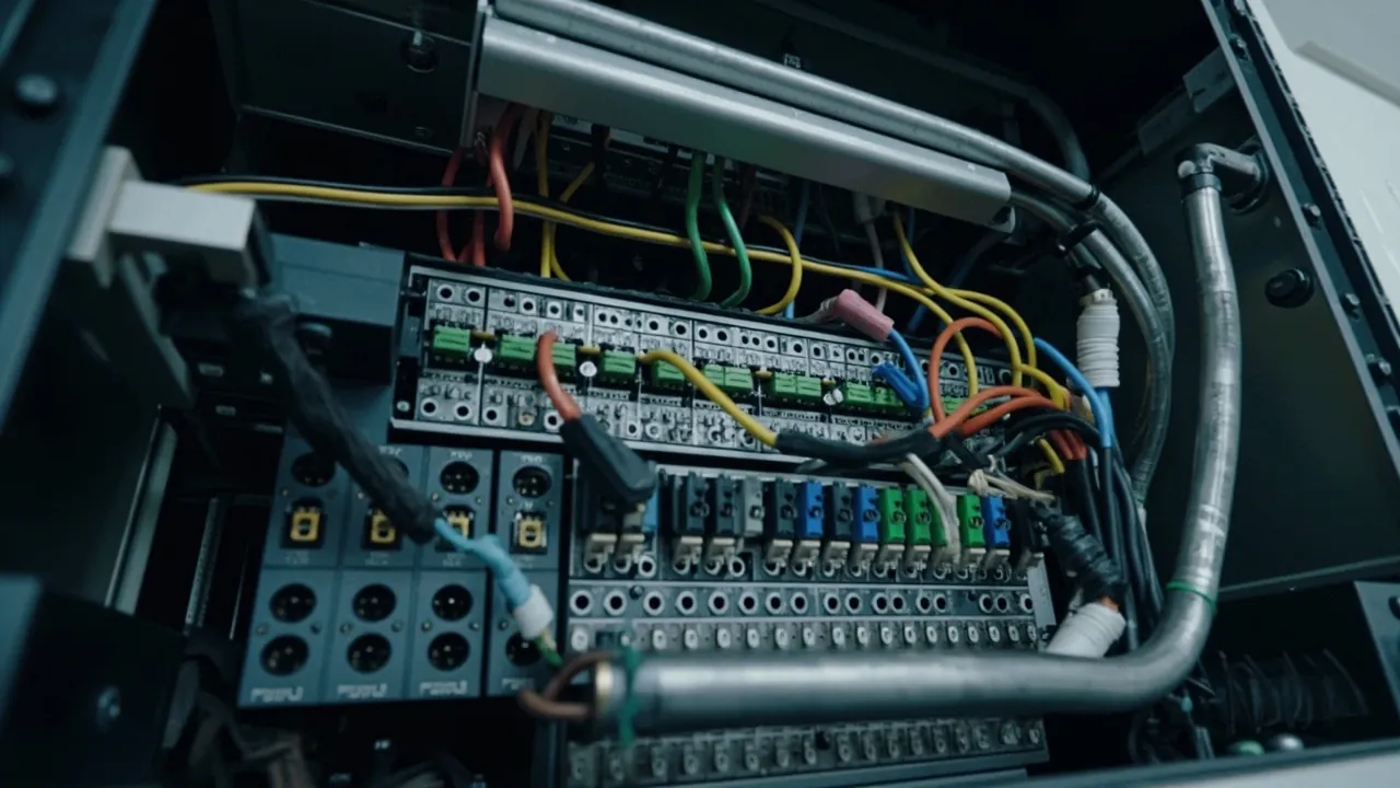
Choose ties rated for ultraviolet outdoors, usually marked UV stabilised and supplied black; standard nylon can fail within six to twelve months in sun, after which bundles fall onto the terminals below. Stainless ties suit high temperature or corrosive locations, though their edges are sharp and need protecting against the jacket. Space ties at 150 to 250 millimetres with one either side of each bend.
Tie in layers rather than gathering everything into one bundle. Form several small sub-bundles by category, fix each independently, then secure them together to a base. Later additions can then disturb one while leaving the others intact. Tighten until the jacket shows no visible indentation, never levered with pliers, since over-tightening compresses insulation and creates a lasting stress concentration.
For management hardware, prefer screw-fixed tie bases to adhesive ones in plastic enclosures. Adhesive loses grip quickly under repeated thermal cycling and condensation outdoors, and whole rows can come away within a year, dropping the harness onto terminals. Metal enclosures can use welded studs or rail-mounted bases.
Labelling must not rely on paper or handwritten tape outdoors. Two durable options are heat-transfer printed sleeves and laser-etched plates. Mark each circuit at both ends, equipment side and terminal side, with identical references matching the drawing, and add a circuit schedule or QR label on the enclosure face so urgent work does not wait for drawings.
Thermal Management Around Heat Sources
Where the box holds power supplies, drives, contactors or high wattage resistors, routing has to account for dissipation at the same time.
Put heat sources high and sensitive items low. Warm air rises, so placing dissipating parts in the upper region lets heat leave through the top, while temperature-sensitive modules such as analogue acquisition stay low and away from them, ideally behind a divider.
Leave convection channels of at least 50 millimetres. Do not pack the space above and below a dissipating component with harness; measured against layouts that keep the channel clear, local temperature can otherwise run 15 to 25 kelvin higher.
Derate conductors themselves. Bundled conductors dissipate heat poorly, so current-carrying capacity needs a correction factor, commonly 0.7 to 0.8 once a certain number run together, with the exact figure taken from the applicable wiring standard. This is routinely missed in dense enclosures, leaving conductors working at or beyond rating for years.
Use heat-resistant cable near sources. Leads running within 50 millimetres of contactors or resistors should be rated to 105 degrees Celsius or more, such as silicone rubber or irradiated cross-linked types.
Eight Wiring Errors
One, harness trapped in the lid joint. This destroys the seal directly. Inspect visually all the way round before closing, and coil surplus length onto tie bases rather than leaving loose tails.
Two, no independent cable support before entry. Suspended weight bears permanently on the gland and slowly opens an eccentric gap. Fix each cable within 300 millimetres.
Three, power and signal in one bundle. Interference shows up as intermittent trips and is notoriously hard to trace. Apply the three levels above.
Four, screens made into pigtails. Almost no shielding effect at high frequency. Clamp through 360 degrees.
Five, two or more cables through one gland. Mixing leaves impressions of unequal depth in the seal and closes neither route properly.
Six, over-bending, particularly right angles forced out simply to make the run look tidy. Verify against the specified multiple of outer diameter.
Seven, high internal temperature with no convection path. Harness wrapped around the heat source forms a local hot spot. Keep the 50 millimetre channel.
Eight, missing labels or labels that disagree between ends. Time lost during fault-finding far exceeds the time taken to label, and during live work it risks operating the wrong circuit.
Completion Checklist
Work through this table before closing the lid, which is the moment when faults are cheapest to find.
| No. | Item | Acceptance criterion |
|---|---|---|
| --- | --- | --- |
| 1 | Harness position | No conductor crosses the joint line that is about to mate |
| 2 | Fill ratio | Summed conductor area in trunking and conduit below 40 percent |
| 3 | Bend radius | Exceeds the specified multiple of outer diameter for every type |
| 4 | Drip loops | Present on all side and top entries, lowest point more than 50 millimetres below the entry |
| 5 | Cable support | Each cable independently fixed within 300 millimetres of the enclosure |
| 6 | Gland torque | Tightened to manufacturer figure; withstands 30 to 50 newtons for five seconds |
| 7 | Power and signal separation | Separate bundles or routes with spacing meeting the design intent |
| 8 | Screen earthing | Single or double ended to design, clamped through 360 degrees |
| 9 | Earth continuity | Resistance from earth bar to main earth not above 1 ohm |
| 10 | Terminal tightness | Sample re-checked to terminal manufacturer torque |
| 11 | Labelling | Both ends of every circuit numbered identically and matching the drawing |
| 12 | Clearance around heat sources | At least 50 millimetres convection channel above and below |
| 13 | Foreign objects | No swarf, wire offcuts or tools left inside |
| 14 | Desiccant | Fitted and indicator still showing normal |
| 15 | Post-closure check | Diagonal sequence to nominal torque, spray screen leaves no water marks |
Frequently Asked Questions (FAQ)
Q: Is it better to pack cables tightly inside a waterproof enclosure? A: No, quite the opposite. First, anything squeezed against the lid joint forces it open and destroys protection outright. Second, dense bundles dissipate poorly, so current-carrying capacity needs derating by a factor around 0.7 to 0.8 or they will run hot and age early. Third, fill ratio in trunking and conduit should stay below 40 percent, beyond which pulling and modification become very difficult. Fourth, cable surfaces act as condensation nuclei, so the fuller the box the larger the condensing area. Leave about 25 percent free volume so both working space and natural convection survive.
Q: Can signal and power share one cable gland? A: Neither electrically nor mechanically. Even where diameters permit, uniform compression cannot be achieved for two different sizes, leaving channels of unequal depth, and galvanically the power circuit induces interference voltage into the signal pair, showing up as intermittent dropouts and drifting readings that are extremely hard to locate on site. Separate holes, separate routes, and keep at least 50 millimetres apart; if they must run together the signal pair has to be screened with the screen terminated as designed.
Q: Are drip loops really necessary, and what happens without them? A: Necessary wherever entry is not at the bottom. A drip loop intercepts water before it reaches the gland and converts a running trickle into the occasional drop. Without it, water flows along the cable to the gland face continuously, which brings three consequences: the sealing insert sits permanently damp and ages faster; once a small gap appears, capillary action keeps feeding it; and in winter the joint can freeze, expand and lever the sealing face apart. The loop costs almost nothing and is the step most often skipped.
Q: Can I skip ferrules and simply twist stranded wire into the terminal? A: No, for two concrete risks. Contact reliability suffers first: individual fine strands spread and partly fracture under screw pressure, reducing effective conducting section so contact resistance rises and worsens over time, ending in a hot or burnt terminal. Second, repeated stripping leaves the wire shorter each time until it no longer reaches. Fit the correct tubular or forked ferrule, crimp with a four-point tool and check with a pull of about 50 newtons. Note that some spring terminals are expressly approved for bare conductors, but only where the manufacturer says so.
Q: Should a screen be earthed at one end or both? A: It depends on signal type and distance. Low frequency analogue, such as 4 to 20 milliamp loops and thermocouples, wants single-end earthing, normally at the control panel, so that earth potential difference cannot drive a circulating current that injects mains hum. High frequency and digital links such as RS485 and Ethernet want both ends, or one direct with the other through a capacitor, ensuring a nearby path for high frequency energy. Beyond thirty metres, both ends becomes the preferred answer, with equal potential assured. Whichever applies, clamp the screen through 360 degrees; a twisted pigtail under a screw does very little at high frequency.
Q: How often should harnesses in outdoor enclosures be checked? A: At least twice a year, once before summer and once after winter. Five items matter: whether ties have aged and snapped, which is the commonest finding since ordinary nylon lasts only six to twelve months outdoors; whether jackets have hardened, cracked or discoloured; whether terminals show verdigris or heat discolouration, quickly screened with an infrared thermometer; whether any bundle has sagged onto terminals or the lid joint; and whether labels remain legible. When ties fail in numbers, replace the whole batch with UV-stabilised types rather than only the broken ones.
Q: Can adhesive tie bases simply be stuck to the enclosure wall? A: Not recommended outdoors for the long term. Adhesive loses grip quickly under repeated thermal cycling and condensation, and a common outcome after six to twelve months is whole rows detaching together with the harness and dropping onto terminals below, causing shorts or pulling connections. Prefer screw-fixed bases, a mechanical mount with a back plate, or cable management features moulded into the enclosure. Where nothing but adhesion is possible on metal, use an industrial tape rated for high temperature and humidity and add a mechanical fixing as insurance.
Q: What changes after adding higher power equipment inside? A: Four things. Volume: recalculate whether 25 percent margin and the required working clearance still exist. Heat: put dissipating parts high and sensitive items low with at least 50 millimetres clearance above and below, and where the housing is cast aluminium or steel, bolt the dissipating part directly to the wall to create a thermal path. Conductor sizing: both high temperature and bundling demand derating, so an increase in conductor size is often required. And revisit moisture control, because added equipment changes both dissipation and air movement, which changes where condensation forms, a subject covered further in outdoor enclosure waterproof design essentials.
Closing Notes and Further Reading
Routing cable inside an outdoor sealed enclosure means satisfying three competing demands within a fixed space. Give way to the seal, so nothing lies across the line that has to mate. Leave the cable slack where it matters, through bend radius, independent support and service length. And give heat somewhere to go, through convection channels, separation of power from signal, and derating. The common enemy of all three is the instinct to push it in and close the lid, which is also the most common working habit on site.
Print the checklist and tick every line before closing. Discovering a fault afterwards costs three to five times what it cost to find earlier. On volume projects, run one complete installation and acceptance cycle on a sample unit, establish the pattern, then replicate it; that step almost always pays for itself.
JUNZHJIA waterproof junction boxes and sealed electrical enclosures come from the brand's Zhongshan plant covering IP65 through IP68, with openings cut to drawing, glands pre-fitted and internal rail layouts arranged to specification, supported by OEM and ODM service, wholesale volumes and worldwide delivery.
Further reading