

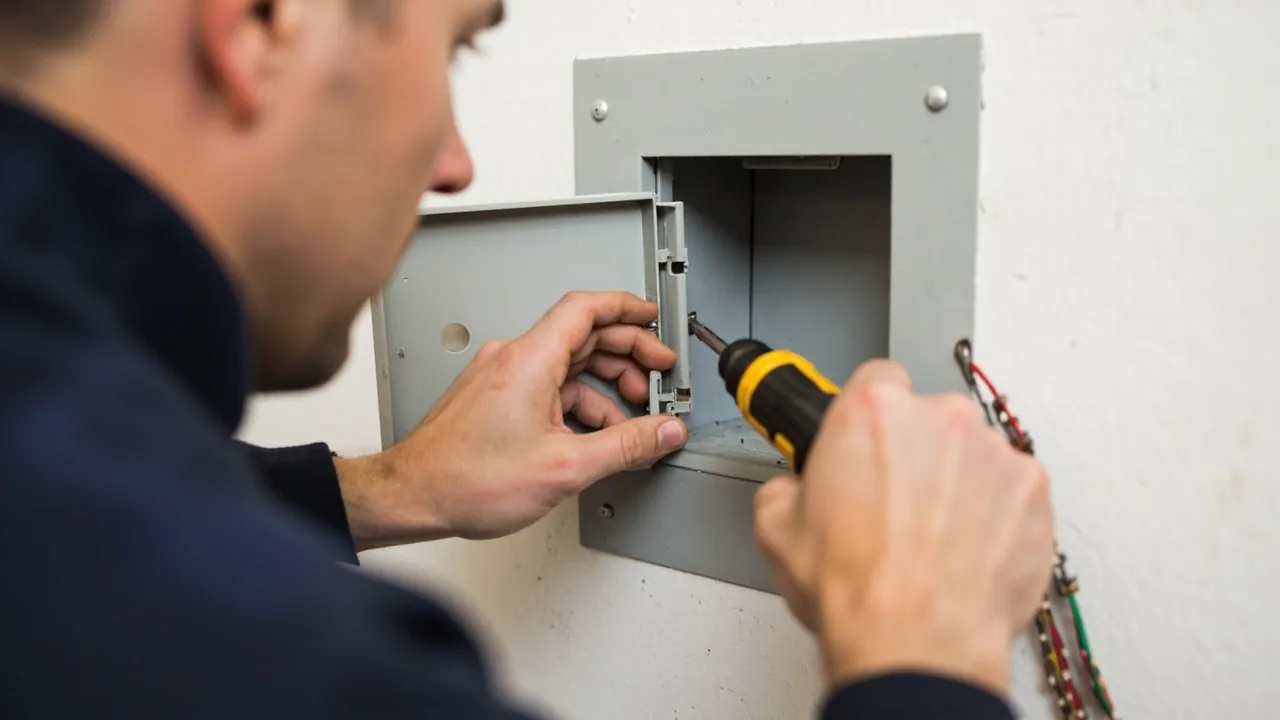
Hand the same model of waterproof junction box to two different crews and the outcome three years later can differ by an order of magnitude. That is not exaggeration. In follow-up site visits we repeatedly see certified IP67 enclosures taking water while a marginally lower rated product installed on another site survives a decade untouched. The difference almost never lies in the box itself. It lies in four operations: where the hole is drilled, how the cable gland is assembled, in what order the lid screws are tightened, and whether anything was done about dripping water. The ingress rating was earned in a laboratory. A box mounted outdoors has to earn it all over again.
This article follows the actual sequence of site work, from unpacking inspection through to the final self-check before energising. Test conditions quoted here come from IEC 60529, Degrees of protection provided by enclosures (IP Code), adopted in China as GB/T 4208-2017. Cable gland requirements follow EN 62444. Torque values, clearances and fill ratios are widely accepted engineering practice; where a manufacturer publishes a specific figure, that figure wins.
Contents
- Three Things to Confirm Before Work Starts
- Tools and Materials Checklist
- Position: Height, Orientation and Clearances
- Fixing Methods: Walls, Posts and Backing Plates
- Drilling: Position, Diameter and Tolerance
- Selecting and Fitting Cable Glands
- Preparing Terminals and Conductors Inside the Box
- Earthing and Equipotential Bonding
- Joint Face Treatment and Lid Tightening
- Managing Condensation: Vents and Desiccant
- Pre-Energisation Checklist
- Eight Frequent Installation Errors
- Frequently Asked Questions (FAQ)
- Closing Notes and Further Reading
Three Things to Confirm Before Work Starts
Three small tasks must be finished before a single hole is drilled. They set the direction for everything that follows, and getting them wrong afterwards costs far more than doing them first.
First, confirm what the supplied enclosure rating actually covers. A box marked IP67 almost always carries a certificate that covers the enclosure body only, meaning the interface between base and lid. The moment a hole is cut on site for a gland, a vent or even a customer logo, that finished-product guarantee becomes a semi-finished one. Order therefore with three documents attached: the third-party IPX7 type test report for the housing, the IP68 report for the gland body including its sealing insert, and an assembly instruction that covers the combination. If the supplier can only produce the housing report, treat the gland as an independent protection element and specify accordingly, ideally using a double-sealed gland design. The reasoning behind this split is set out in more detail in What Is the IP67 Rating: The Hard Threshold for Outdoor Low-Voltage Waterproof Enclosures.
Second, confirm the cable route and the true cable diameters. Drawings usually give circuits but rarely give outer diameters, yet glands are selected by clamping range. A single PG13.5 thread will be offered with several rubber inserts, commonly 6 to 12 millimetres, 5 to 9 millimetres or 3 to 7 millimetres. An outer diameter that lands close to the edge of a range behaves completely differently from one that sits in the middle of it. Measure each cable on arrival at three points and take the largest reading, because extruded jackets are rarely perfectly round.
Third, confirm the structure and load capacity of the mounting surface. A mid-sized sealed enclosure fully populated with terminals and cable can exceed eight kilograms. Mounting across two studs of lightweight partition, or fixing onto decorative cladding over insulation, leads over time to screw holes loosening under vibration and self-weight, and the compression on the joint face decays with them. Where necessary use through-bolts with a backing plate behind the wall, or move to a floor stand or a clamped post bracket.
One more habit worth adopting: take ten minutes of photographs before starting, recording the original wall condition, the cable entry position and how water drains nearby. If a seepage dispute arises later, that set of pictures settles the boundary of responsibility, and it also helps to work out whether water travelled along the cable or came through from behind the mounting face.
Tools and Materials Checklist
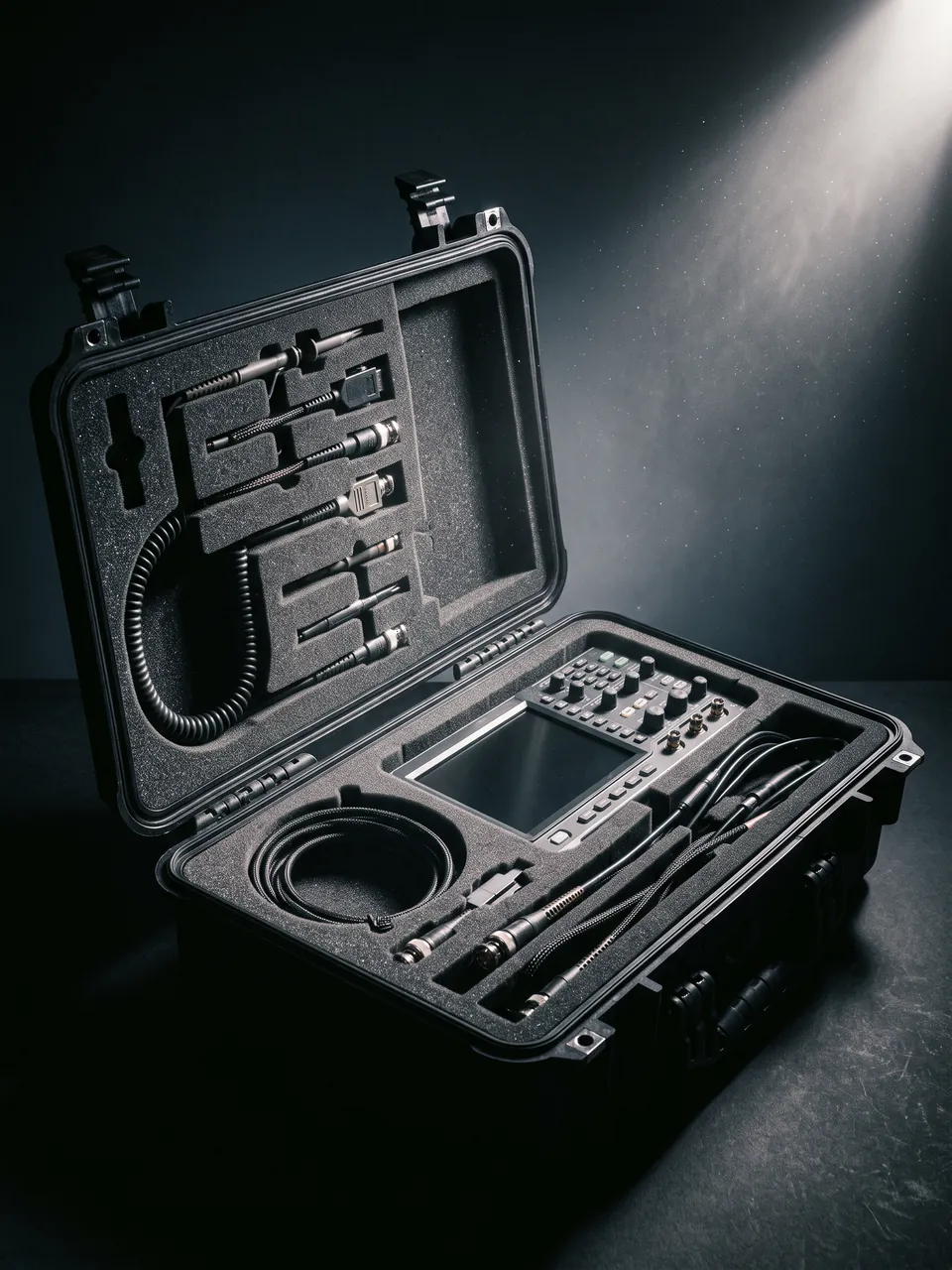
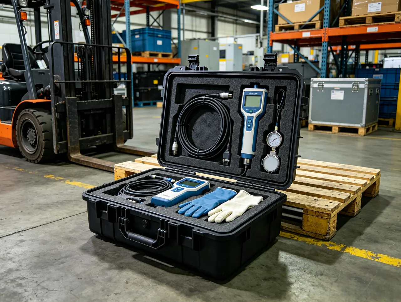
Many installation defects come from the wrong tool rather than poor craftsmanship. The table below lists what genuinely matters. Missing any one item is a reason to delay the start.
| Category | Item | Specification |
|---|---|---|
| --- | --- | --- |
| Tightening | Torque screwdriver or torque wrench | Range 0.5 to 5 Nm, tolerance within plus or minus 10 percent, calibrated yearly |
| Cutting | Step drill or hole saw | Cobalt step drill for metal housings, dedicated hole saw for plastic; never burn holes with a soldering iron |
| Deburring | Countersink tool or half-round file | Both faces of every hole must be chamfered; burrs cut cable jackets |
| Sealing | Neutral-cure silicone sealant | External supplementary use only; never a substitute for the factory gasket |
| Sealing | Rubber backing washers | Used to reinforce thin walls, thickness 1.5 to 3 millimetres |
| Terminating | Crimp lugs and matching crimper | Four-point or die-type crimper required; long-nose pliers are not acceptable |
| Terminating | Wire stripper | Adjustable type; slitting insulation with a knife risks nicking conductors |
| Marking | Label printer or weather-resistant labels | Must resist UV and low temperature; paper labels fail within six months outdoors |
| Testing | Digital multimeter and insulation tester | A 500 volt insulation tester suits most low-voltage circuits |
| Testing | Low-pressure water spray | Garden sprayer or hose on a gentle setting for preliminary screening |
| Safety | Voltage tester and insulating gloves | Verify absence of voltage before work; never trust the switch position alone |
Consumables to keep on hand include stainless locknuts, blanking plugs with elastomer seals for spare holes, UV-stabilised nylon cable ties, butyl or silane-modified sealing tape, desiccant sachets, and where flexible conduit is used, the matching fittings.
A word on tightening tools: a calibrated torque driver is not optional. The lid screws of an ABS waterproof enclosure usually have a nominal torque somewhere between 1.2 and 2.5 newton metres, which happens to sit below the force most adults apply by hand. Tightened by feel, the scatter across ten fixing points regularly exceeds 40 percent. The loose points become tomorrow's leak paths; the over-tight ones crack plastic bosses or strip threads.
Position: Height, Orientation and Clearances
Choose the position well and half the battle is won. Choose badly and no ingress rating will save you.
Raising the box is the first rule. Set the height against the highest water level recorded historically, plus margin, rather than against a comfortable eye height. In practice: alongside open ground or landscaping, keep the lowest edge of the enclosure at least 300 millimetres above finished level; at basement ramps and road low points, take the recorded local flooding level and add at least 500 millimetres, or switch to post mounting when raising is impossible; on roof decks, keep at least 150 millimetres above the finished waterproofing and use a stand rather than fixing directly to the membrane; in snow country the lowest edge should sit above maximum snow depth, often 600 millimetres or more; along corridors that get hosed down, if raising is impossible then at least turn the lid away from the jet and add a deflector plate.
Orientation is about where water runs, not about appearance. The lid should face away from the prevailing weather or towards whichever side gives the easiest maintenance access, and it must never face upwards. Boxes are often laid flat with the lid pointing at the sky purely because wiring is easier that way. Outdoors it is the worst possible attitude. Rainwater pools against the joint line, ultraviolet exposure concentrates on the top face, and the gasket ages several times faster under the combination of standing water and direct sun. As analysed in Why Do Outdoor Waterproof Boxes Leak: Five Seal Failure Causes and Fixes, water rarely punches straight through a visible joint; it creeps along contact surfaces and arrives later.
Allow more clearance than feels necessary. Commonly forgotten items include at least 100 millimetres around the sides to swing a screwdriver, at least 300 millimetres on the opening side to pull cables out during service, at least 500 millimetres from heat sources such as flue pipes or transformer radiators, and at least 20 millimetres between adjacent enclosures so side walls can dissipate heat.
Finally, never mount an enclosure directly beneath a drainage outlet, inside a wash-down zone, or under the drip line of an eave. Eave drip is small in volume but it strikes the same seam year after year, and that accumulated scouring life exceeds what occasional storms deliver.
Fixing Methods: Walls, Posts and Backing Plates
Different substrates call for different fixings, and two requirements drive the choice: nothing loosens, and the joint face is never disturbed.
| Substrate | Recommended fixing | Key points |
|---|---|---|
| --- | --- | --- |
| Solid concrete or brick | M6 or M8 expansion bolt, or plastic plug with stainless screw | Hole 5 to 10 millimetres deeper than the plug; blow out dust; keep height difference between fixing points within 1 millimetre |
| Aerated block or hollow brick | Chemical anchor or hollow-substrate anchor | Standard plugs will not grip and can burst the block |
| Steel column | Band clamp or welded stud | Treat welds against corrosion; line the clamp with rubber to prevent galvanic contact |
| Lightweight stud partition | Through-bolt with backing plate | Backing plate at least 2 millimetres thick, extending 20 millimetres beyond the four holes |
| Timber post, temporary only | Stainless wood screw with washer | Timber loosens quickly; use only for temporary installations |
| Profiled metal roof panel | Aluminium base bracket, sealing rivets, sealant | Requires a secondary flashing, otherwise the original roof waterproofing is compromised |
Three details are routinely overlooked. First, fixing holes must not break into the seal groove. Some waterproof enclosures provide external mounting lugs precisely so that nothing is drilled inside; when someone drills through the back wall of the enclosure for convenience, the hole often lands on the line of the seal groove and creates a straight channel from the rear into the interior. Use the external lugs. If a hole through the floor of the enclosure is unavoidable, the bolt must be fitted with an elastomer washer, the head side sealed with neutral silicone, and the result verified by spraying.
Second, washers should be one size larger than the screw head. Use stainless flat washers of 12 to 16 millimetres outside diameter so the screw head does not bear directly on a plastic lug and crack it through local stress.
Third, do not pull the enclosure flat with extra fixing points. When the mounting face is uneven, add shims or a back plate. Progressively tightening screws until a plastic housing conforms leaves it under permanent stress, and stress cracking can appear months later, typically radiating from the mounting holes.
Drilling: Position, Diameter and Tolerance
Drilling is the only irreversible operation in the whole installation, and it is the main route by which a finished product loses its rating.
Priority order for cable entries: bottom first, lower side wall second, upper side wall third, top last. Keep all entries on the bottom face or the lowest band of the side wall so that neither water nor dust collects at the opening. When routing forces a side entry, stagger the holes rather than lining them up at one height, which also leaves room for a spanner. Where a top entry truly cannot be avoided, fit a rain hood or a downward elbow; never let rainwater run along the cable and pool at the face of the gland.
Hole diameter is set by the gland thread, not by the cable diameter. Typical sizes are listed below.
| Thread | Recommended hole diameter (mm) | Common clamping range (mm) |
|---|---|---|
| --- | --- | --- |
| PG7 | 12.5 to 13.0 | 3 to 6.5 |
| PG9 | 15.2 to 15.8 | 4 to 8 |
| PG11 | 18.6 to 19.0 | 5 to 10 |
| PG13.5 | 20.4 to 21.0 | 6 to 12 |
| PG16 | 22.5 to 23.0 | 10 to 14 |
| PG21 | 28.3 to 29.0 | 13 to 18 |
| M12x1.5 | 12.0 to 12.5 | 3 to 6.5 |
| M16x1.5 | 16.0 to 16.5 | 4 to 8 |
| M20x1.5 | 20.0 to 20.5 | 6 to 12 |
| M25x1.5 | 25.0 to 25.5 | 11 to 16 |
| M32x1.5 | 32.0 to 32.5 | 15 to 21 |
PG and metric threads of nominally the same size are not interchangeable. The PG form has a thread angle of 80 degrees against 60 degrees for the metric form. Forcing one into the other damages the thread so that it feels tight while only half the flank depth is engaged, and vibration then releases it. The result is a total loss of protection, and almost impossible to spot visually.
A few further hard rules apply. Edge-to-edge distance between adjacent holes should be at least 6 millimetres, and the distance from a hole edge to the enclosure outline at least 10 millimetres, otherwise the locknut cannot clamp properly and the wall becomes a weak band. Clearance between hole and gland should stay within 0.5 millimetres on a side; a larger gap lets the sealing insert extrude into it under compression and turns into a leak path rather than a seal.
In technique, centre-punch first to stop the bit wandering, particularly on curved or uneven walls. On plastic, keep the speed between 500 and 800 revolutions per minute; faster, and the hole mouth melts and forms a raised lip. On metal, use cutting fluid and ease the feed as the bit breaks through so it does not snatch and tear the wall. Chamfer both faces of every hole and run a finger around the bore afterwards; this single step decides how many years the cable jacket survives. Spare openings take purpose-made blanking plugs with seals. Nuts, tape and insulation tape do not count.
When drilling is finished, clean every fragment out of the enclosure with compressed air or a lint-free cloth. Swarf left inside becomes a conducting bridge between terminals, and in damp conditions it initiates tracking.
Selecting and Fitting Cable Glands
The cable gland, also called a cable sealing gland or cord grip, is the most important link in the protection chain and the one most often shortcut. Across a large number of outdoor water ingress cases, the fault sits at the gland rather than at the lid joint.
Selection rests on four factors. Thread form comes first: match the thread the housing was cut for, and accept no substitutes. With wall thickness above 3 millimetres there is no latitude, and thin-walled boxes may need a locknut on both faces. Clamping range is second: place the measured cable diameter in the middle of the stated range rather than at its edge. A cable measuring 11.8 millimetres belongs in a 10 to 14 millimetre gland, not a 6 to 12 millimetre one, because an edge fit cannot compress evenly. Ingress rating is third: the gland body should at least match the enclosure, and IP68 is the sensible default. Pay attention to how it is stated, since IP68 without a stated depth and duration, for example IP68 at 2 bar for 60 minutes, is not a complete specification. Material is fourth: nickel-plated brass or polyamide PA66 suits general duty; acidic, saline or chemical atmospheres call for 316 stainless or UV-stabilised engineering plastic; bridges and pump rooms with continuous vibration need a gland with an anti-loosening ring or an integrated strain relief.
Assembly follows a fixed sequence. Do not skip a step.
- Dismantle the gland and check that the sealing insert is intact, not twisted and not nicked, and that its lip faces the direction shown in the manufacturer's drawing.
- Slide the nut, insert and body onto the cable in the manufacturer's order. An O-ring left off or doubled changes everything.
- Leave enough cable inside: enough to reach the furthest terminal plus a further 100 to 150 millimetres for future re-termination.
- Strip the outer sheath without scoring the inner insulation. On screened or armoured cable, treat the screen or armour for single-end or double-end bonding as the design requires rather than trimming it off out of habit.
- Pass the body through the hole from outside, fit the washer and locknut, and run it down by hand.
- Tighten the locknut with an open-ended spanner. As a guide, nylon M20 takes roughly 3 to 5 newton metres, metal M20 roughly 8 to 10, and PG13.5 roughly 4 to 6. Avoid heavy leverage with an adjustable wrench: too much torque leaves white stress marks around a plastic hole and then cracks it.
- Finally tighten the compression nut with a torque tool, typically 2.5 to 4 newton metres for nylon. Once seated, the cable should resist a firm pull by hand.
- Perform a pull test on every cable. Apply roughly 30 to 50 newtons axially for five seconds; there should be no movement. Record the result in the commissioning sheet.
One prohibition deserves emphasis: never put two cables through one gland. Even where the two diameters add up neatly, the gap between them forms a capillary channel that draws water in, and two different diameters can never be compressed evenly by a single insert. You end up with two gaps instead of one seal.
Preparing Terminals and Conductors Inside the Box
Order inside the enclosure decides whether the installation can still be serviced in three years.
Choose rail-mounted screw or spring terminals rather than twisted joints wrapped in tape. Two options dominate, and the trade-off is straightforward. Spring-cage terminals resist vibration and never need re-tightening, which suits anything that moves, but they require the matching ferrule unless the manufacturer explicitly permits bare conductors. Screw terminals are universal and cheaper, and their price is a re-tightening round three to six months after commissioning, particularly after the first full hot-cold cycle. In corrosive atmospheres specify tinned copper or stainless metal parts, because bare copper grows verdigris in damp, sulphur-bearing air and contact resistance climbs.
Key control points for conductor preparation are listed below.
| Item | Requirement | Why it matters |
|---|---|---|
| --- | --- | --- |
| Strip length | Matches the terminal barrel depth, leaving 0.5 to 1 millimetre visible | Too much exposes conductor, too little and the screw misses it |
| Strand treatment | Never cut strands; twist and tin, or fit a ferrule | Loose strands are a common source of hot joints |
| Crimp lugs | Matched to both conductor size and stud diameter | Use a four-point crimper, then pull-test at 50 newtons |
| Identification | Numbered sleeve or durable label at both ends of every circuit | Avoid paper labels outdoors; heat-shrink printed sleeves last |
| Bend radius | Six times outer diameter for single core, eight for flexible, ten for screened or coaxial | Tight bends fracture internal strands |
| Spare length | Furthest terminal plus 100 to 150 millimetres | Allows re-termination later without re-pulling cable |
| Trunking fill | Total conductor area below 40 percent of the trunking section | Overfilling traps heat and prevents the lid seating |
Calculate usable volume in advance. A practical figure is that each 2.5 square millimetre circuit, allowing for terminal, tie and routing space, occupies roughly 0.25 to 0.35 litres, and then add 25 percent on top. An over-filled box causes three problems in sequence: the lid presses on the harness so the joint face cannot mate; dense bundles trap heat and age the insulation early; and pulling one cable during fault-finding drags half the others out, at which point the whole box gets re-terminated.
Earthing and Equipotential Bonding
Outdoor electrical enclosures fall into two material families with different earthing requirements, and both must be satisfied.
A plastic enclosure does not conduct, so there is no concept of earthing the shell. There must, however, be a dedicated earth terminal bar inside, and if a galvanised mounting plate is fitted, that bar must be bonded to it. Every protective conductor and screen entering the box terminates at that bar, which in turn connects to the main earth with a conductor no smaller than the incoming protective conductor.
Metal enclosures need that internal bar and additionally an equipotential bond on the shell itself. Use the earth stud provided by the manufacturer with a serrated washer and run it to the earth network. Where no stud exists, drill a dedicated earthing hole, fit a stainless bolt and terminal, abrade the contact face clean of oxide and coating, apply a conductive paste, and tighten. Size the bonding conductor for the maximum prospective fault current; for small outdoor enclosures this is usually not less than 4 square millimetres. Watch galvanic corrosion too: where an aluminium shell meets copper lugs, insert a tinned transition piece or an insulating washer.
Joint Face Treatment and Lid Tightening
This is the final step that converts every earlier effort into actual protection, and it is the one most readily sacrificed to finishing quickly.
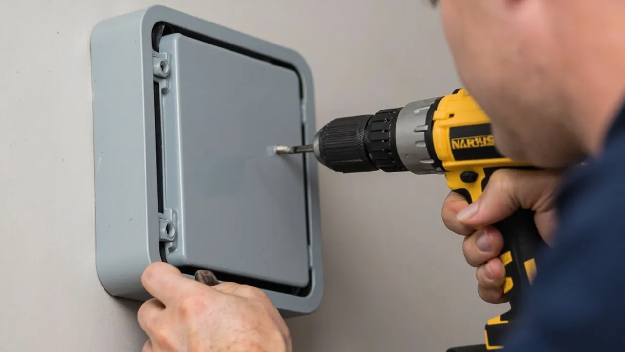
Inspect the seal first. Wipe the groove and the gasket with a clean cloth and confirm that no grit, swarf or water remains. Where a gasket length has to be cut on site, join the ends with a mitred lap and a trace of silicone; a butt joint leaves a step. Failure on site is frequently caused by nothing more than a strand of hair or a grain of sand, because a particle under half a millimetre across is enough to hold open a channel right through the compressed rubber.
Check the harness next. Confirm that no conductor lies across the joint face. With spring terminals in particular, the spare length should be coiled, tied and clipped to an internal cable anchor rather than heaped near the lid seam.
Tighten in a defined sequence. Run all screws down by hand first, then take them to 50 percent of the nominal torque in diagonal order, then bring them to 100 percent in the same order. Even, multi-pass compression gives every part of the gasket the same amount of squeeze. Tightening one screw fully at a time guarantees that some region stays slack.
On lubrication, a thin film of silicone grease on the gasket face helps fill micro-scale roughness and prevents the rubber bonding to the housing, which makes the next opening easier. Use nothing petroleum-based, and use very little; after spreading, there should be no visible bead.
Regarding external sealing, a bead of neutral silicone along the top edge and down both sides of a wall-mounted enclosure forms an effective rain cap, but the lower edge must be left open. Sealing all four sides traps water that does get behind the box and lengthens the contact time between water and housing, which is the opposite of what you want.
Managing Condensation: Vents and Desiccant
A frequent site report reads: the inside of the box was covered in droplets while the outside stayed dry. Nine times out of ten that is condensation, not leakage, and the two call for opposite remedies.
Condensation forms because air inside carries moisture and the wall temperature falls below dew point overnight. In regions with a large diurnal swing, even a perfectly dry, correctly assembled sealed enclosure can accumulate a surprising amount of water over a season. Neither GB/T nor the IEC system provides an IP classification for condensation, so it has to be solved by engineering measures.
Three measures work. The first is a breather vent with a hydrophobic membrane, usually expanded PTFE with pore sizes in the order of 0.1 to 1 micrometre. It passes air molecules while blocking liquid water, equalising pressure without giving up the ingress rating. Mount it low on a side wall, angled downwards, so dust, insect nests or moss do not accumulate on the membrane; in dusty locations choose a capped version and put it on the replacement schedule. The second is desiccant inside the enclosure. Indicating silica gel at roughly 5 to 10 grams per litre of usable volume works well, positioned so the indicator can be read without dismantling anything. The third is reducing the moisture source: cap cable ends before pulling, work in dry weather where possible, and close any ventilation opening that serves no purpose.
It is worth stating plainly that total sealing is not the answer. A sealed box breathes under diurnal cycling just as much: falling temperature creates internal negative pressure that draws damp air in along the seams, and rising temperature pushes the soft sealing faces outward. Over repeated cycles this fatigue accelerates rather than prevents failure, a point developed further in Extreme temperature effects on outdoor enclosure materials.
Pre-Energisation Checklist
Twenty minutes spent walking this table before switching on avoids most rework. Print it as a paper form, tick it item by item, and have both parties sign.
| No. | Check item | Acceptance criterion |
|---|---|---|
| --- | --- | --- |
| 1 | Mounting rigidity | No movement or noise when the enclosure is rocked firmly by hand |
| 2 | Fixing points | All mounting holes used; none left open and unsealed |
| 3 | Entry direction | Bottom or low side entry; top entries fitted with rain protection |
| 4 | Gland thread form | Same system as the housing; no mixing of PG and metric |
| 5 | Gland tightness | Withstands a 30 to 50 newton pull for five seconds without movement |
| 6 | Spare openings | Closed with purpose-made sealed blanking plugs |
| 7 | Joint face cleanliness | No debris or damage visible; gasket free of twists and cuts |
| 8 | Lid tightening | Diagonal sequence to manufacturer torque; every screw present |
| 9 | Foreign objects | No swarf, wire offcuts or tools left inside |
| 10 | Terminal tightness | Sample re-checked to the terminal manufacturer's torque |
| 11 | Circuit identification | Both ends of every circuit numbered and matching the drawing |
| 12 | Earth continuity | Resistance from the earth bar to the main earth not above 1 ohm |
| 13 | Insulation resistance | Measured at 500 volts; above the specified minimum and showing no downward trend |
| 14 | Condensation and standing water | No visible water film or droplets; desiccant still active |
| 15 | Spray verification | No trace of water on the inside walls after five minutes of low-pressure spraying |
Item 15 deserves a note. Site conditions are not laboratory conditions, but low-pressure water from a garden sprayer or a hose on the gentle setting, applied for one minute from each direction, concentrating on the four corners, around the glands and along the upper edge of the mounting face, then opening the lid and wiping the interior with tissue, will screen out the great majority of assembly faults at effectively no cost. It will not detect slow capillary seepage. For genuinely high-risk positions, such as somewhere expected to flood, arrange a simplified immersion screen following the IEC 60529 IPX7 approach.
Eight Frequent Installation Errors
Finally, eight mistakes that dominate site inspections. None of them stems from not knowing the standard; every one of them comes from saving effort.
Tightening by feel. Covered above, but the underlying belief deserves repeating: many supervisors treat "until it stops turning" as correct, whereas with plastic threads the thread has usually stripped, or the mounting boss has whitened under stress, before anything actually stops. Only a torque tool fixes this, and it needs to be written into the briefing.
Top entry without protection. The mechanism is not rain falling from above. It is a stable film of water forming between cable and gland, driven inward by gravity and capillary action together. A rain hood, or simply a downward drip loop before entry, costs very little and changes the outcome immediately.
Mixing PG and metric threads. This appears most in retrofit work, where both thread types sit in the stores. Being able to turn a few threads does not mean the forms match. Try a thread gauge or a sample of the correct part: three full easy turns with no binding is acceptable, whereas any tightness, tilt or thread debris means stop and change to the right specification.
Drilling or notching the sealing face. Some installers cut a small notch inside the groove purely to route a cable more neatly. That single cut takes an IP67 enclosure down to around IP20, and it is nearly invisible, so only a spray test reveals it.
Omitting the earth terminal. The justification offered is that plastic does not conduct, so no earth is needed. But the metal mounting plate, the DIN rail and the cable screens all need a common reference point, and without one there is no discharge path for surges from lightning or inductive load switching.
Two cables in one gland. Already noted; the on-site tell is a sealing insert bearing impressions of unequal depth, which means two different diameters compressed by one insert. Split them into separate holes.
Unsupported cable run. Where cable arrives from a tray or buried duct without its own fixing nearby, its full suspended weight bears on the gland and slowly opens an eccentric gap. Fix every cable independently within 300 millimetres of the enclosure.
Filling the box to capacity. A packed enclosure has its lid pressing on the harness. It looks closed, but the harness absorbs the clamping force and part of the joint face lifts. Leaving 25 percent volume free should be written down as a hard requirement, not left to judgement.
Frequently Asked Questions (FAQ)
Q: Can the supplier drill the entry holes before delivery? A: Yes, and it is strongly recommended. For volume projects, typically fifty units or more, supplying the drawings with the order lets the factory cut every hole on a jig, fit the glands and run batch immersion sampling. The pass rate is one to two orders of magnitude above site drilling. Provide the hole layout, diameter tolerance, thread system and gland part numbers together with the purchase order, and ask for assembly verification records per batch. JUNZHJIA supplies this kind of OEM and ODM service across its waterproof junction box range, with hole positions laid out to drawing coordinates, which suits repeatable project orders particularly well.
Q: Is top entry ever acceptable, and can anything be done to rescue it? A: It is not recommended, but where it cannot be avoided it can be mitigated. Three measures work: route the cable down and round through 90 degrees before entering so a drip loop forms below the gland; fit a hooded gland with the mouth pointing downwards; and add a fixing clip ahead of the gland so the cable weight is not carried by the joint. Double the spray test duration on any top entry point during commissioning. Understand that these steps reduce rather than remove the risk. Where the contents are valuable or the location floods, change to bottom entry.
Q: An enclosure is already installed badly. Anything that avoids taking it down? A: It depends on the fault. Missing rain protection along the upper edge of the mounting face can simply be added with neutral silicone, leaving the bottom open. Slack glands can be re-tightened and pull-tested in place. Mixed PG and metric threads must be changed; there is no reliable repair. A notch cut across the sealing face, or a harness trapped in the lid joint, means replacing the lid or the housing and starting again. The test is simple: anything fixable from outside stays up; anything that touches the sealing line itself goes back to zero.
Q: What matters when several enclosures are mounted side by side? A: Three things. Heat, because plastic enclosures shed most of their heat by natural convection from the side walls, so abutting them stacks the thermal resistance; leave at least 20 millimetres between them, more if the contents dissipate significant power. Access, because the lid opening direction needs planning so one open lid does not block its neighbour. And water, because the gap between units collects dust and standing water, so fit a continuous deflector along the top. Where space genuinely is not available, use one larger enclosure rather than several abutting.
Q: When should the first re-inspection happen? A: Three milestones. The first one to three months after commissioning: visual check plus re-tightening of the lid screws, since plastic parts and gaskets show clear stress relaxation and compression set early on, and this one visit recovers the loss. The second after the first full summer or winter: check the gasket for hardening, the housing for discolouration and embrittlement, and the metal parts for corrosion. The third at twelve months: a system-level round including spray screening, insulation resistance measurement and desiccant replacement. After that, routine inspection at six to twelve month intervals is adequate, shortened to quarterly in coastal or chemical environments.
Q: What do I do when a screw hole in a plastic enclosure has stripped? A: Identify the location first. On a lid hole, usually caused by excessive torque earlier, press in a threaded insert, either a heat-set brass nut or a stainless wire thread insert, and carry on; if the same position strips twice, replace the lid. On a mounting lug, the usual cause is pulling the enclosure down onto an uneven face, so change to through-bolting with a backing plate and close the original lug hole with a sealed blanking plug. Prevention is a single rule: torque tools throughout, never feel.
Q: Can I paint the outside of the enclosure for extra waterproofing? A: Almost always pointless. Paint acts on the outer skin and does nothing for a joint that has already formed a gap, and a coating with a different expansion rate may itself crack and flake. The measures that do help are targeted: a rain deflector along the upper mounting edge, thread sealant or a little PTFE tape on gland threads, and a purpose-made rain cover above the unit. Genuinely high-risk locations deserve a higher rated product or a verified outer shroud rather than a brush. Also note that if paint blocks a breather vent, the condensation problem gets worse rather than better.
Q: Can a plastic enclosure be mounted directly onto a steel column? A: Yes, with two cautions. On corrosion, there is no galvanic couple between plastic and steel, but make sure no burr or weld spatter on the contact face abrades the housing; and where stainless fixings meet a carbon steel column a potential difference does exist, so protect the contact face or insert an insulating washer. On vibration, steelwork near running plant, on bridge decks or in pipe racks vibrates noticeably, so use spring washers or locknuts and pay particular attention to fixing points loosening at the six-month check.
Closing Notes and Further Reading
The protection an IP67 outdoor junction box finally delivers is the product of rating multiplied by installation quality, not the sum of them. The selection side is settled on the drawing board. Roughly seventy percent of the remaining variables sit with the installation crew: which face was drilled, whether nominal torque was reached, whether every gland is properly matched, and whether room was left for condensation management and future service. None of this requires advanced theory. What it does require is being written into a work instruction and an acceptance sheet, and somebody actually ticking the boxes.
Take the tool list, the checklist and the eight errors in this article and turn them directly into an appendix to your project's installation procedure for outdoor sealed enclosures. For volume work, moving hole cutting and gland assembly back into the factory is the single highest value step available.
JUNZHJIA waterproof junction boxes and sealed electrical enclosures are built at the brand's Zhongshan plant, covering IP65 through IP68, with custom hole layouts, factory-fitted glands and batch sampling, supplied wholesale worldwide.
Further reading