

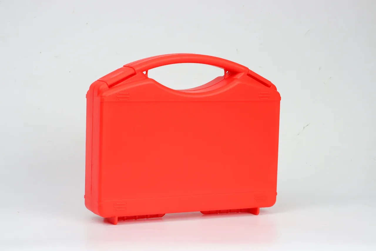
Quick answer: An Equipment Protection Case spec comes from four inputs: payload, drop height, stack height and temperature. They fix the cavity, the cavity plus wall fixes the envelope, the perimeter the latch count.
Table of contents
- Four inputs behind an Equipment Protection Case spec
- The cavity dimension chain, link by link
- Wall thickness and ribs from drop energy
- Latch count and hinge span by perimeter
- Turning the spec into a drawing
- FAQ
1. Four inputs behind an Equipment Protection Case spec
An Equipment Protection Case is not drawn first and filled later. Payload, drop height, stack height and temperature are inputs; the envelope is an output.
| Input | Example | What it sets |
|---|---|---|
| Payload | 18 kg | Wall thickness, rib height |
| Drop height | 1.2 m | Bumper thickness, foam clearance |
| Stack height | 4 high | Lid flatness, pad width |
| Temperature | -20 to 55 °C | Resin grade, gasket hardness |
Temperature is the input people forget. Polypropylene loses about 60 percent of its notched impact at -20 °C, so another grade behaves like another product. Silicone flexes at -40 °C while neoprene stiffens near -20 °C, and at 55 °C a loaded side wall creeps inward within a year.
2. The cavity dimension chain, link by link
The dimensions of an Equipment Protection Case form a chain, and each link needs a stated basis.
| Link | Example | Basis |
|---|---|---|
| Equipment envelope | 420 × 300 × 150 mm | Measured outline, with connectors |
| Clamp and hand clearance | 20 mm per side | Lifting, cabling, fingers |
| Cavity net size | 460 × 330 × 170 mm | Sum, rounded |
| Outside envelope | 480 × 350 × 190 mm | Cavity plus 3.0 mm wall and 8 mm rib |
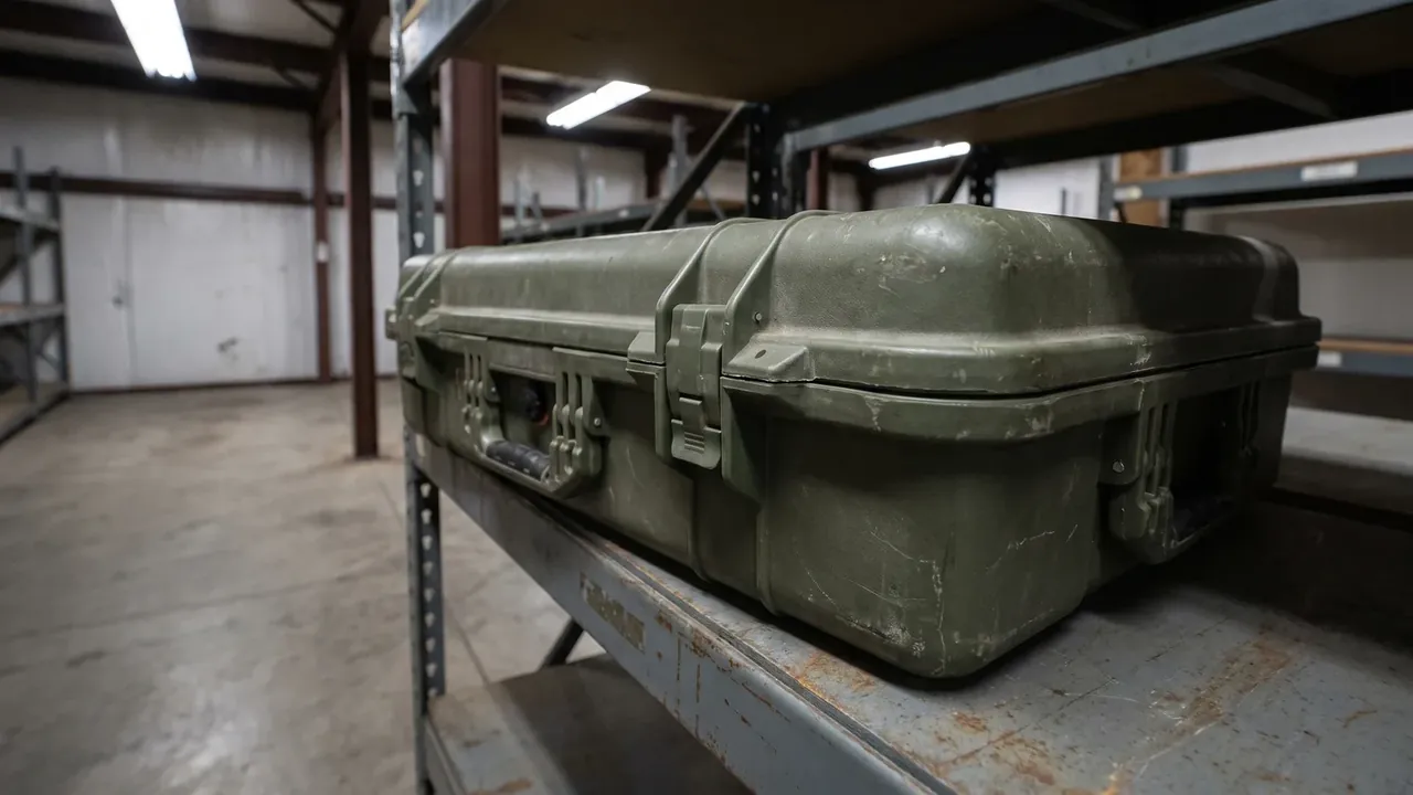
Cavity figures are quoted at the narrowest point, never at the opening, and corners carry an R8 radius.
The chain ends at the stacking face: four cases at 18 kg load the bottom unit with 72 kg, yet its lid centre collapses. Ribs there are spaced closer, not thicker.
3. Wall thickness and ribs from drop energy
Wall thickness on an Equipment Protection Case is back-calculated from drop energy: 18 kg at 1.2 m arrives with about 212 J, absorbed in milliseconds by bumpers, wall and foam.
- Main wall 3.0 mm; below 2.5 mm the keeper root cracks first.
- Ribs 8 mm high on a 120 mm pitch; each extra 2 mm adds 30 percent section modulus.
- Rib roots at R1.5, because a square transition tears on impact.
- Bumpers 6 mm, separate, so a knock swaps a corner.
- Feet 12 mm high, 30 × 40 mm patch.
Stiffness is not the goal. A wall too rigid returns the impact into the equipment.
4. Latch count and hinge span by perimeter
Latches on an Equipment Protection Case are spread by perimeter: a 480 × 350 mm body measures 1660 mm, two on the long side at 240 mm and one per short side.
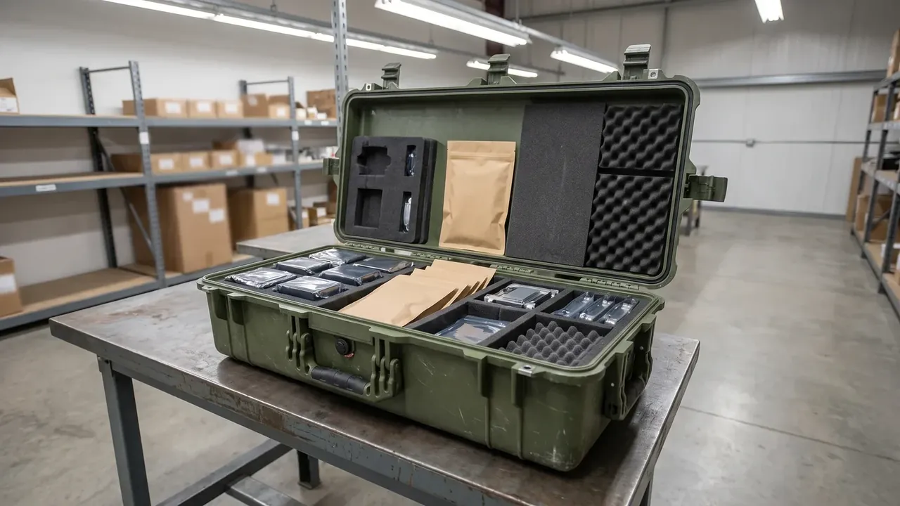
Each latch clamps at 60 to 90 N, about 150 N per metre, pressing a 3 mm gasket to 2.1 mm.
| Parameter | Value | Basis |
|---|---|---|
| Latch count | 4 | One per 300 mm of perimeter |
| Latch spacing | 240 mm | No wavy gasket impression |
| Hinge span | 320 mm | Past 400 mm the lid lifts |
| Screw torque | 2.5 N·m | No stripping or cracks |
Six latches at 160 mm load the first three and leave the rest slack; a 400 mm span sags the lid 0.4 mm.
5. Turning the spec into a drawing
The specification of an Equipment Protection Case ends as drawing numbers in a fixed order: cavity, envelope, holes, material, inspection. Reverse it and tolerances never recover.
The 460 mm cavity carries ±0.5 mm, the 480 mm envelope ±0.8 mm, warp inside 1.0 mm per metre. The gasket groove is 0.2 mm wider than the strip and 0.6 mm shallower, placing compression at 25 to 30 percent.
| Inspection item | Value | Method |
|---|---|---|
| Cavity size | 460 × 330 × 170 mm, ±0.5 | CMM or gauge |
| Lid warp | 1.0 mm per metre | Plate and feeler |
| Salt spray | 480 h, no perforation | Spray cabinet |
| Drop | 1.2 m per face | Loaded production drop |
| Thermal cycling | -20 to 55 °C, 5 cycles | Climatic chamber |
Conclusion
An Equipment Protection Case spec is one chain from four inputs: payload and drop set structure, stack height and temperature set material, cavity plus wall gives the envelope. Run the chain and the specification of an Equipment Protection Case stops depending on trial fitting.
This article discusses only the container (case body) side of specifications and design intent, and does not cover any handling, loading or use of the contents.
Related Reading
- What an equipment case has to stop
- Cavity clearance and shock allowance
- Configurations for transport and storage
- Structure of fire equipment cases
Related Products
- 8 Series — Gun Cases; Military Equipment Cases; Camera Equipment Cases; Drone Cases; Watch Cases; Knife Cases; First Aid Cases; Electronics Equipment Cases
- WL8-2812 PP Gun Case — model WL8-2812
- All protective cases and toolboxes: 7 series, 158 models