

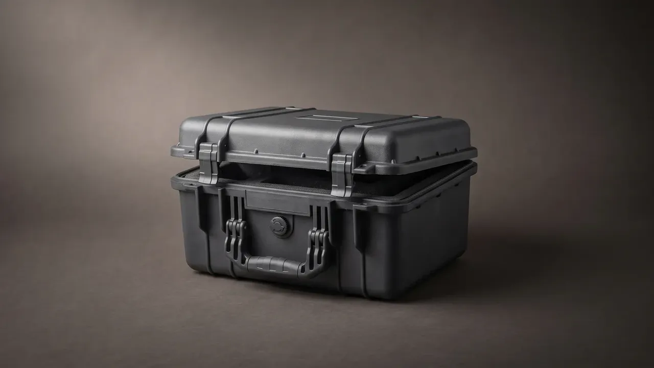
Quick answer: An ESD lining works only when surface resistance and a full ground path agree: 10⁶ to 10⁹ Ω bleeds charge slowly and 1 MΩ limits the return.
Table of contents
- Three Resistance Bands Inside a Case
- Carbon-Loaded Foam or Coated Surface
- Volume, Surface and Point-to-Point
- The Ground Path: 1 MΩ and 0.5 mm²
- Proving Triboelectric Voltage Under 100 V
- Splices and Adhesive: Three Breaks in Continuity
- FAQ
1. Three Resistance Bands Inside a Case
Surface resistance decides which band a liner belongs to. Conductive sits at 10² to 10⁵ Ω, dissipative at 10⁶ to 10⁹ Ω, insulative above 10¹² Ω. Cross one decade and the behaviour changes.
| Band | Surface resistance | Volume resistivity | Typical material | Where it fits |
|---|---|---|---|---|
| Conductive | 10²–10⁵ Ω | 10²–10⁴ Ω·cm | carbon-loaded XPE | earthed benches |
| Dissipative | 10⁶–10⁹ Ω | 10⁴–10⁸ Ω·cm | loaded EPE, fabric | ESD lining, gauge boxes |
| Insulative | above 10¹² Ω | above 10¹⁴ Ω·cm | plain EPE, EVA | packing with no ESD need |
An ESD lining usually takes the dissipative band, and the reason is how fast charge leaves rather than how completely. A conductive liner dumps 500 V in under 10 ms, spiking current into the amp range that a thin gate oxide will not survive. The dissipative band takes 0.2 s to 2 s for the same 500 V, holding current in the milliamp range.
The insulative band fails by accumulation. Plain EPE at 10¹⁴ Ω traps 3 kV to 8 kV after rubbing and releases it through the next hand that touches it. Black foam proves nothing: colour may come from carbon or from pigment, and only an ohmmeter separates the two.
2. Carbon-Loaded Foam or Coated Surface
Two ESD lining routes reach 10⁶ Ω on paper and behave nothing alike once cut.
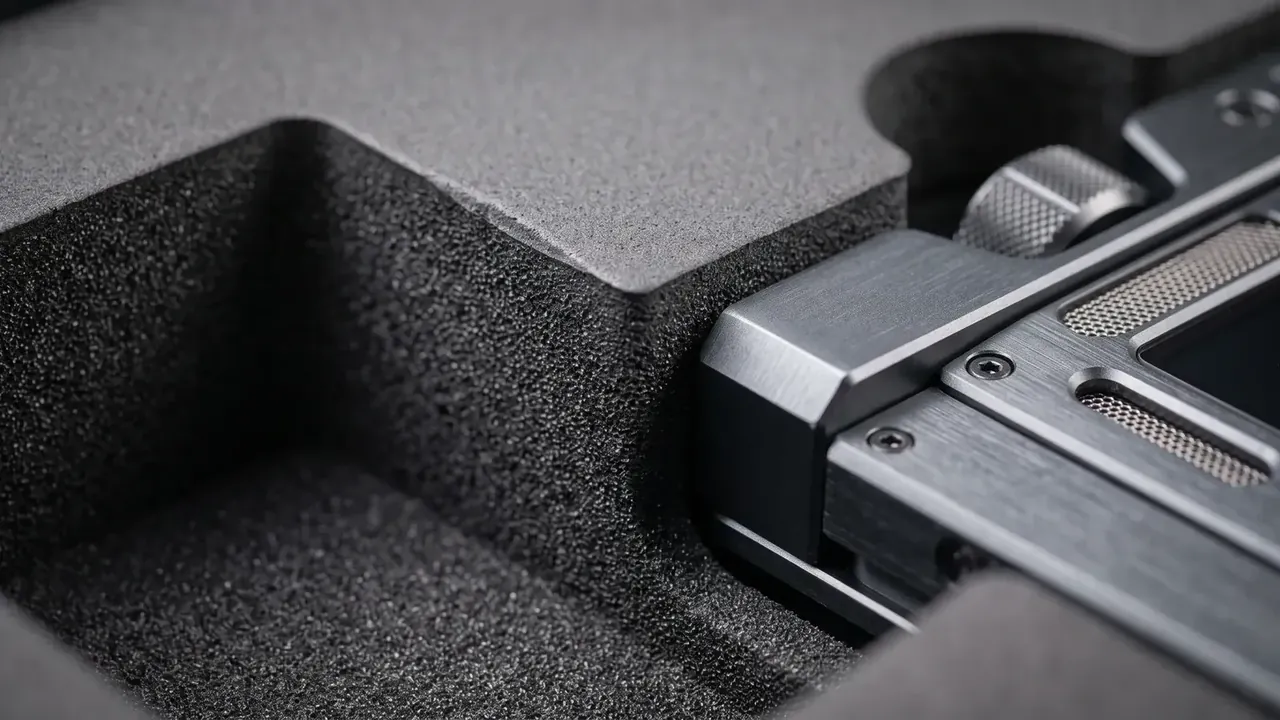
Carbon loading makes the whole section conductive. XPE or EPE takes 15% to 25% carbon black before foaming, pulling volume resistivity to 10³–10⁵ Ω·cm, so a cut face still conducts. Three costs follow: colour is limited to black, rebound drops 10% at 20% loading, and density climbs from 30 kg/m³ to 60–90 kg/m³, adding about 200 g per case.
Coating stays surface-only. Plain EPE is sprayed with 20 μm to 50 μm of conductive coating or laminated with conductive fabric, reaching 10⁴–10⁶ Ω on the skin while the bulk keeps 10¹⁴ Ω·cm. Charge stops at the cut, because the exposed section is an insulator.
Coatings age. After 500 strokes of 0000 steel wool under 500 g, surface resistance climbs from 10⁵ Ω past 10⁷ Ω, and any breach exposes 10¹⁴ Ω. A laminate splits the difference: fabric on top, 30 kg/m³ EPE below, spot-bonded with conductive adhesive, 15% heavier than plain foam and 20% cheaper than a fully loaded sheet.
3. Volume, Surface and Point-to-Point
Three numbers get quoted interchangeably and come from different fixtures.
ANSI/ESD S4.1 covers work surfaces, with two 2.3 kg electrodes 254 mm apart at 10 V or 100 V, read after 15 s. ANSI/ESD S11.11 covers planar surface resistance with rings or bars, again at 10 V or 100 V. Volume resistivity follows ASTM D257 with a 63.5 mm electrode and comes out in Ω·cm.
Voltage choice shifts the answer by one or two decades. Use 10 V below 10⁶ Ω and 100 V above it, and a dissipative liner straddles that line, so both readings belong in the report rather than whichever passes.
Point-to-point is the number that describes an ESD lining honestly. It asks whether the far cavity corner connects to the grounding stud through foam, splice, adhesive and wall. Four or five interfaces sit in series and one insulator voids the chain, so a liner reading 10⁶ Ω as a sheet often reads 10¹¹ Ω once fitted.
4. The Ground Path: 1 MΩ and 0.5 mm²
An ESD lining with no ground is a floating capacitor.
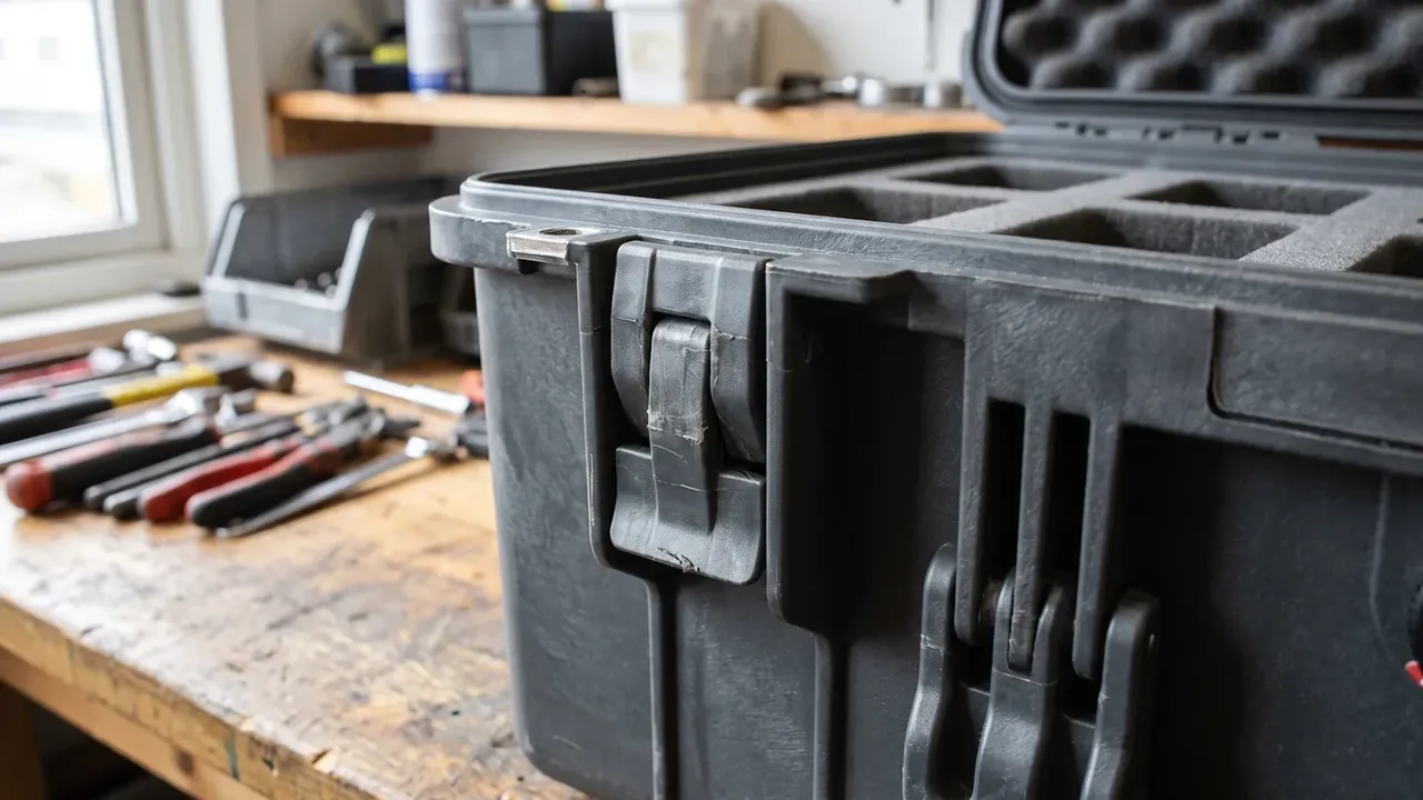
The 1 MΩ resistor at the stud protects people, not components: at 250 V it holds current to 250 μA, below the perception threshold. Without it the liner ties straight to earth and current depends on skin resistance alone.
A 0.5 mm² conductor is enough, kept under 1 m and measured below 1 Ω. Thicker cable buys nothing, since the bottleneck is the termination, where one badly crimped lug contributes 5 Ω to 20 Ω.
Bonding is where most builds fail. Foam pressed against plastic touches over a few newtons and lands above 10⁹ Ω, an open circuit in practice. Fit a conductive fabric tail bonded with conductive adhesive to a metal insert, holding the joint under 10 Ω, or add a stud through the 3.0 mm wall.
5. Proving Triboelectric Voltage Under 100 V
An ESD lining that passes as a sheet may still fail once installed, so charge generation needs its own test.
Wrap a 500 g slider in nylon, stroke the liner 10 times over a 200 mm path, and read peak voltage with a field meter at 25 mm. The target is under 100 V, because above it a part is at risk the moment it is lifted.
Run the harshest condition. At 23 °C and 12% RH the reading peaks, since the water film is thinnest and charge cannot escape; the same liner at 50% RH often reads a third of that. Quoting only the 50% figure is quoting good weather.
Decay time tells more. Charge the liner to 1000 V and time the fall to 100 V; the dissipative band allows 2 s, and that figure folds the stud, splices and adhesive into one result.
6. Splices and Adhesive: Three Breaks in Continuity
Large cases rarely take one sheet, and every joint is a candidate break.
The first is the butt splice. Two sheets each read 10⁶ Ω, yet across the seam the meter shows above 10⁹ Ω, because cut faces carry no path. Overlap 10 mm and press conductive tape across the joint, extending 20 mm onto each sheet.
The second is hot melt. At 10¹⁴ Ω·cm a few dots insert an insulator between conductors, so use conductive adhesive or keep bonding off the discharge path.
The third is the folded corner, where 20 μm of coating crazes at R5 and surface resistance jumps from 10⁵ Ω past 10⁸ Ω. Carbon-loaded foam has no such failure, which is why it holds up in irregular cavities.
Accept by sampling three points per metre and reading the two furthest apart; under 10⁹ Ω passes, three decades above the material figure to allow for interfaces.
Conclusion
An ESD lining rests on three numbers: 10⁶ to 10⁹ Ω at the surface, a 1 MΩ resistor at the stud, and a 0.5 mm² conductor holding the path under 1 Ω. Material choice is only the first step, since failures cluster at the bond to the shell, the splice between sheets and the crazed coating at a folded corner. Hold triboelectric voltage under 100 V and decay under 2 s, and the certificate stops being the only evidence.
This article discusses only the container (case body) side of specifications and design intent, and does not cover any handling, loading or use of the contents.
Related Reading
- Foam cutting methods compared
- Custom foam inserts: specifications and cavity tolerance
- Rotomoulded case bodies: wall thickness and tooling
Related Products
- 8 Series — Gun Cases; Military Equipment Cases; Camera Equipment Cases; Drone Cases; Watch Cases; Knife Cases; First Aid Cases; Electronics Equipment Cases
- WL8-2812 PP Gun Case — model WL8-2812
- All protective cases and toolboxes: 7 series, 158 models