

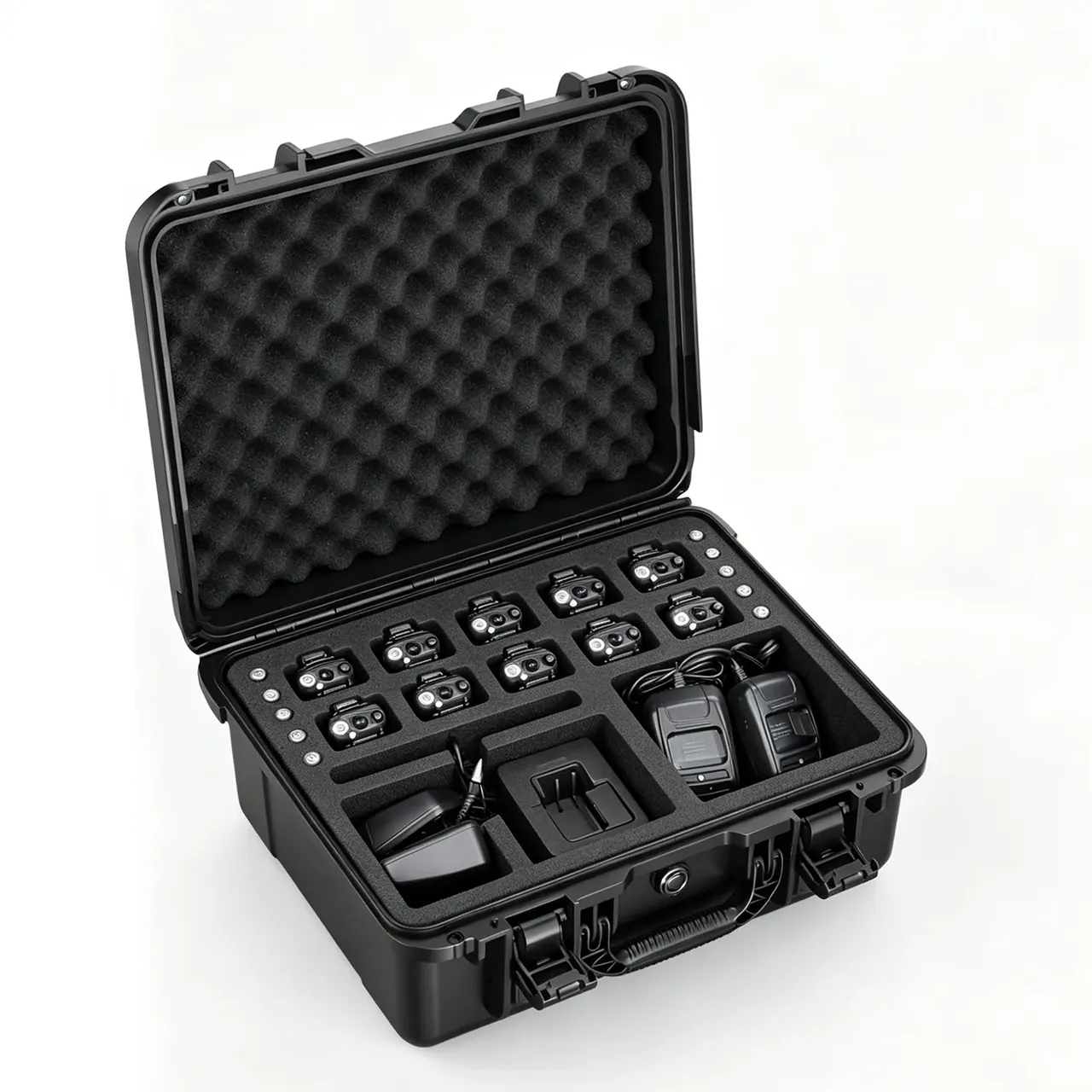
Quick answer: A heavy duty impact-resistant mechanical parts box is 600×400×320 mm, 7.8 kg empty, 45 kg loaded, 52.8 kg in total, on 6 mm walls and an 8 mm base.
Table of contents
- Three handling methods, three load points
- Single-point maths at 52.8 kg
- Wall thickness, base ribs and fork entry height
- Why a 1.5 m drop must leave the sidewall uncracked
- FAQ
1. Three handling methods, three load points
Two people split 52.8 kg between them, about 260 N a hand. Each handle is rated 600 N, which looks like a 2.3x margin until the two walk out of step and the peak lands on one handle near 400 N. That is why the heavy duty impact-resistant mechanical parts box uses a 40 mm diameter, 8 mm thick boss at each root.
A forklift cares about two numbers: fork entry height and base ribs. Entry height is 100 mm, and below about 90 mm the forks bite nothing but the base edge, so the longer lever bows the 8 mm plate. Three ribs at 120 mm pitch turn two fork points into two lines.
A crane hook uses four lifting holes at 400 N each with 25 mm slings. At 45° from vertical each sling pulls 183 N, at 60° it reaches 259 N, at 75° 500 N; the wall around the heavy duty impact-resistant mechanical parts box holes runs 10 mm and the sling angle is capped at 60°.
| Handling method | Load point figure | Structure that answers it |
|---|---|---|
| Two-person carry | about 260 N per handle | 2 handles, 40 mm root boss |
| Forklift | 100×30 mm contact band | 8 mm base, 3 ribs at 120 mm |
| Crane | 259 N per lifting hole | 4 holes, 25 mm slings |
2. Single-point maths at 52.8 kg
7.8 kg empty plus 45 kg loaded makes 52.8 kg, or 518 N. Over two handles that is 260 N each; over four lifting holes it is 130 N, or 183 N once the slings sit at 45°. Ratings of 600 N and 400 N then give 2.3x and 2.2x, close enough that neither looks generous.
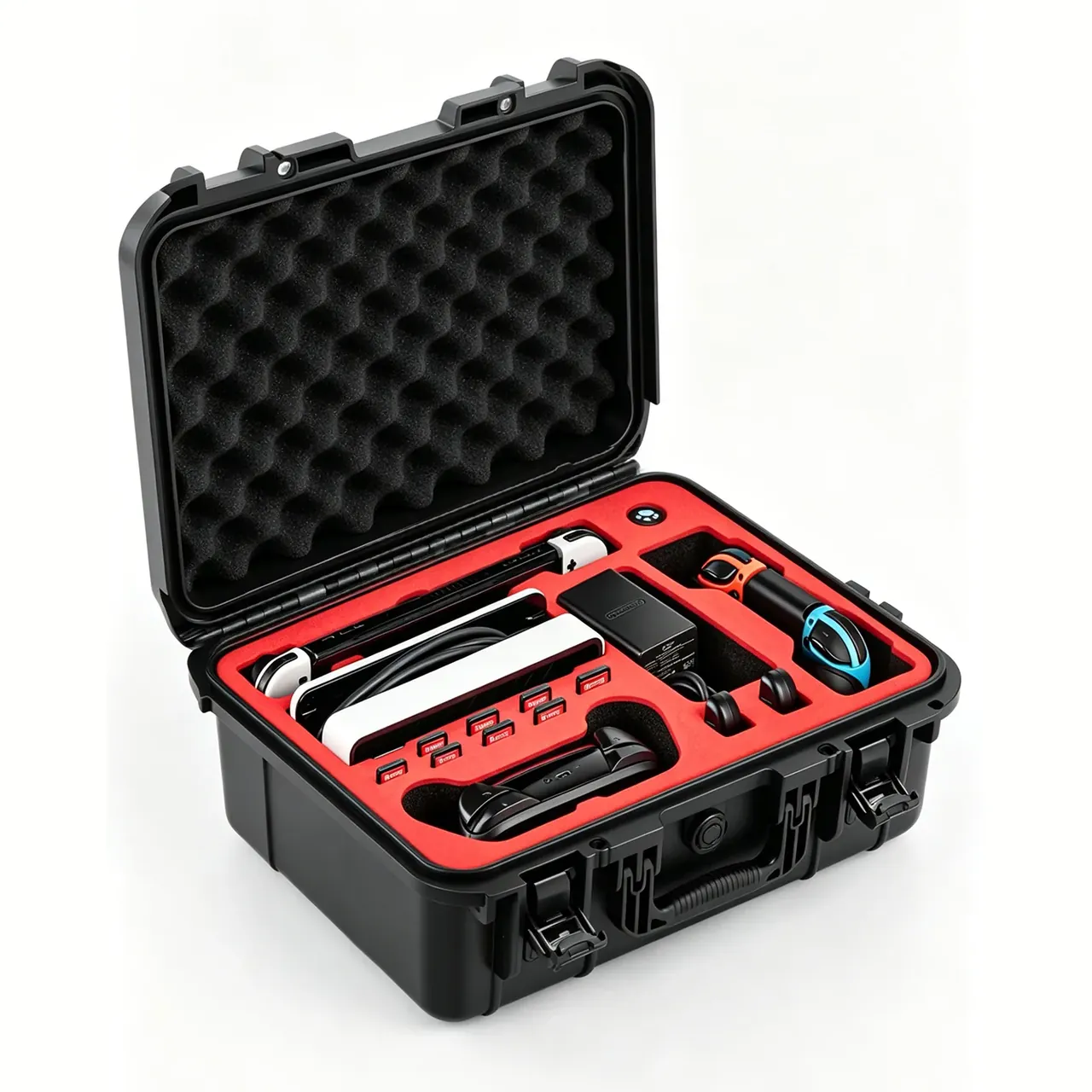
The φ8 mm hinge pin is the third single point. A lid and pad near 3.2 kg at 50 g in a 1.5 m drop puts 1 570 N of shear into the pin, an 8 mm stainless pin carries 50 mm², so stress is 31 MPa against a 200 MPa allowable.
Two latches at 350 N each cannot hold 1 570 N, and on this heavy duty impact-resistant mechanical parts box they are not meant to: in a drop the load path runs through the rim, where the lid tongue seats and the 6 mm sidewall carries shear.
| Load point | Design value | Basis |
|---|---|---|
| One handle | 600 N | 518 N over two hands, 400 N peak |
| One lifting hole | 400 N | 130 N split, 259 N at 60° |
| Hinge pin | φ8 mm, 31 MPa shear | 3.2 kg lid at 50 g |
| Latches | 2 × 350 N | Static only, drop goes to the rim |
3. Wall thickness, base ribs and fork entry height
A 6 mm sidewall and an 8 mm base differ because the loads differ. Walls bend and resist puncture, and 6 mm at 120 mm rib pitch is stiff enough. On the heavy duty impact-resistant mechanical parts box the base takes the fork load, so it runs 8 mm plus three full-length ribs, widening the contact band from 30 mm to 60 mm and cutting edge pressure from 0.36 MPa to 0.18 MPa.
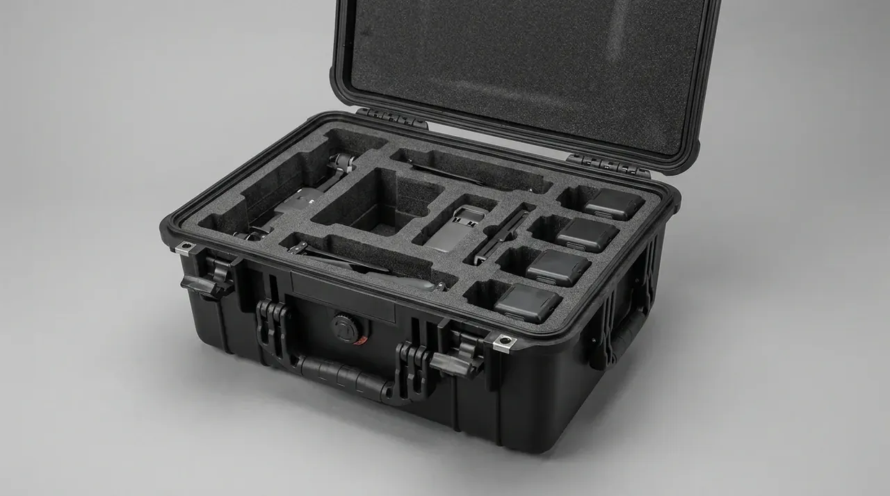
Fork entry height of 100 mm means clear space, not rib height. The 12 mm ribs sit inside that envelope, so the channel stays 100 mm; drivers come in at 5° and the tip rises 35 mm, which is why base corners get a 15 mm chamfer.
Rib pitch of 120 mm is calculated. An 8 mm plate spanning 120 mm deflects about 0.4 mm; stretch the span to 200 mm and it reaches 1.9 mm, and whatever does not spring back is the set left after the forks withdraw from the heavy duty impact-resistant mechanical parts box.
| Design value | Where it sits | What it does |
|---|---|---|
| 6 mm wall | four sides | Bending and puncture |
| 8 mm base | floor | Takes the fork load |
| 3 ribs at 120 mm | base | Spreads points into lines |
| 15 mm chamfer | base corners | Leads the fork tips in |
4. Why a 1.5 m drop must leave the sidewall uncracked
A 1.5 m six-face drop is a whole-box judgement. The order is fixed: base, four sides, then lid, one face at a time. Three things are checked: cracks in the sidewall, latches that let go, and a rim out of line.
A 2 J drop hammer at −25 ℃ sits under that. Polypropylene turns brittle in the cold, and 2 J is a 1 kg hammer falling 200 mm onto a 6 mm wall; the heavy duty impact-resistant mechanical parts box that passes at room temperature often cracks at the rib root at −25 ℃, where the weld line meets three stress directions.
Turnover of 60 trips a year sets the life basis. Five years gives 300 trips, or 600 impacts at two per trip, against a single six-face round in the lab. The lab round is a sample check, not a life prediction.
Conclusion
Carrying presses the handles, the forklift the ribs, the crane four lifting holes; average-value design loses at every peak. At 52.8 kg the figures 600 N, 400 N and a φ8 mm pin settle the margins, while a 1.5 m drop and a 2 J hammer at −25 ℃ draw the floor. Handling first, then wall thickness, then rib positions; reverse it and the base dishes first on any heavy duty impact-resistant mechanical parts box.
Related Reading
- Feet, base area and stacking load
- Static and dynamic handle loads
- The order of a drop test sequence
- Where heavy rolling instrument cases fit
Related Products
- 8 Series — Gun Cases; Military Equipment Cases; Camera Equipment Cases; Drone Cases; Watch Cases; Knife Cases; First Aid Cases; Electronics Equipment Cases
- WL8-2812 PP Gun Case — model WL8-2812
- All protective cases and toolboxes: 7 series, 158 models