

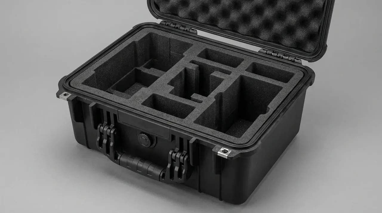
Quick answer: Industrial automation parts safety transit case rests 4 layers on four 1200 mm2 feet, keeping lid deflection to 2.0 mm and liner shift to 1.2 mm.
Table of contents
- Industrial automation parts safety transit case: foot contact area
- Lid ribs and stacking deflection
- Deflection readings after four-layer stacking
- Measuring liner shift after drop
- Foot wear review at cycle end
- FAQ
1. Industrial automation parts safety transit case: foot contact area
Four feet sit at the corners of the Industrial automation parts safety transit case, each presenting 1200 mm2 of contact to the bearing face. The shell spans 620 × 450 × 280 mm outside with a 555 × 385 × 215 mm cavity, a 4.2 mm wall, 7.2 kg empty and 16 kg loaded. Foot centres are aligned to lid-rib crossings so force runs straight down the ribs, not sideways into the wall.
With 16 kg loaded across 4 layers, the bottom lid carries the three cases above it, and 1200 mm2 sets the contact pressure while lid deflection of ≤2.0 mm is the end reading of that chain. Feet are pressed on a flat plate for 24 h, then unloaded and dent depth measured. The Industrial automation parts safety transit case records the seat position on the tool drawing before each lot.
| Stack layers | Contact per foot | Cumulative load |
|---|---|---|
| 1 layer | 1200 mm2 | 16 kg |
| 2 layers | 1200 mm2 | 32 kg |
| 3 layers | 1200 mm2 | 48 kg |
| 4 layers / 24 h | 1200 mm2 | 64 kg |
2. Lid ribs and stacking deflection
Whether the lid survives 4 layers comes down to rib layout. The Industrial automation parts safety transit case uses a crossed centre with a closed perimeter, rib height matched to the 4.2 mm wall, so an upper foot lands exactly on a rib crossing and the lid bends rather than being punched through locally.
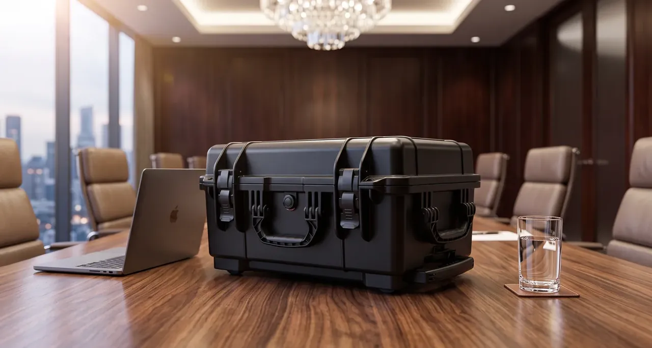
The 1200 mm2 area governs how pressure spreads, the crossed ribs govern bending stiffness, and together they hold the 4-layer / 24 h reading within ≤2.0 mm. Both entries go onto one stacking card for the Industrial automation parts safety transit case. With the lid closed, five points are read — mid-span, four corners and the foot landings — and the group passes only when none exceeds 2.0 mm.
| Foot position | Contact area | Check |
|---|---|---|
| front left | 1200 mm2 | dent depth |
| front right | 1200 mm2 | dent depth |
| rear left | 1200 mm2 | rib alignment |
| rear right | 1200 mm2 | rib alignment |
3. Deflection readings after four-layer stacking
Four layers held for 24 h is the set condition for reading deflection. The Industrial automation parts safety transit case stacks 16 kg cases level, aligns each foot to the rib crossing below, and reads mid-span sag without unloading after the hold. The criterion is ≤2.0 mm, measured as lid movement against the mouth plane rather than foot compression.
Deflection is read from the bottom up. Stack 7.2 kg empty once and 16 kg loaded once to fix the loaded state as the governing condition. Then build from 1 to 4 layers, logging a mid-span reading at each step. Subtract the before-and-after 24 h values to locate which layer carries the creep increment. If it concentrates at the bottom, rework the flatness of the 1200 mm2 foot seats. Merge the four layer readings into one table and flag any layer above 2.0 mm. The four-layer set is then complete.
4. Measuring liner shift after drop
After a 1.0 m drop the acceptance line is liner shift of ≤1.2 mm. The Industrial automation parts safety transit case measures how far the liner moves against a shell datum, taking one component normal to the lid and one along the long edge; either over the line is logged. At impact, 4 latches at 420 N each lock lid to shell, and the liner is held by its base pad and lid frame.
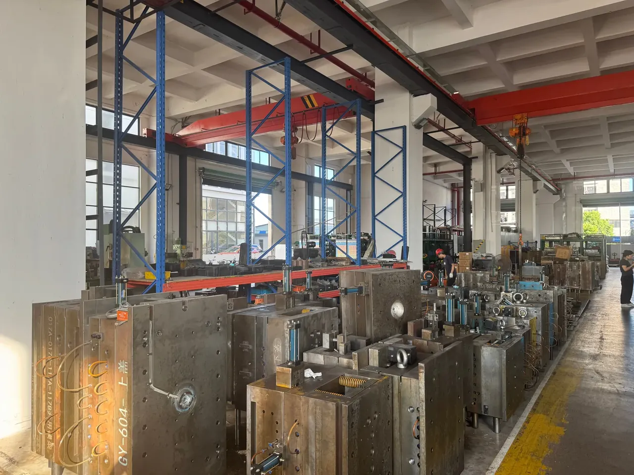
Liner shift is judged on one line only, 1.2 mm, with no second band.
A closed-lid round is run again at cycle end. After 3500 open-close cycles the shift is re-read; only with the frame unsunk and feet still tight is the 1.0 m value still held to ≤1.2 mm. IP66 and a 72 h salt fog are logged as box-side environmental behaviour, not stated as a certification result.
| Deflection reading | Condition | Verdict |
|---|---|---|
| 1.2 mm | 4 layers / 24 h | pass |
| 1.8 mm | 4 layers / 24 h | pass |
| 2.0 mm | 4 layers / 24 h | pass |
| 2.3 mm | 4 layers / 24 h | recheck |
5. Foot wear review at cycle end
Stop the rig at 3500 open-close cycles to inspect foot wear. The Industrial automation parts safety transit case counts each cycle as one lid lift, and repeated stacking pressure thins the 1200 mm2 contact face until pressure redistributes. Measure the remaining thickness of all four feet first, then check each contact area for uneven wear, and finally re-run the ≤2.0 mm lid-deflection baseline.
The 1.0 m drop check looks at structure, the cycle check at wear, and the two are filed apart. The handover card for the Industrial automation parts safety transit case has two columns: one fixes 620 × 450 × 280 mm outside, 555 × 385 × 215 mm cavity, 4.2 mm wall, 7.2 kg empty and 16 kg loaded; the other logs 4 layers / 24 h, lid deflection ≤2.0 mm and liner shift ≤1.2 mm. JUNZHIJIA supplies only structure and inspection records for this model.
Conclusion
The Industrial automation parts safety transit case spreads stacking load over four feet at 1200 mm2 each and catches bending with crossed lid ribs, holding deflection to ≤2.0 mm after 4 layers / 24 h and liner shift to ≤1.2 mm after a 1.0 m drop. The 620 × 450 × 280 mm envelope, 4.2 mm wall, 16 kg load and 3500 cycles only make sense read alongside the feet and ribs. JUNZHIJIA ships structure and inspection records for this model.
Related Reading
- ISTA 3A and 3E transit vibration compared
- Airline checked baggage: straps and label placement
- Export case packing and container loading
- Case load capacity and standing on the lid
Related Products
- 8 Series — Gun Cases; Military Equipment Cases; Camera Equipment Cases; Drone Cases; Watch Cases; Knife Cases; First Aid Cases; Electronics Equipment Cases
- WL8-2812 PP Gun Case — model WL8-2812
- All protective cases and toolboxes: 7 series, 158 models