


Quick answer: Injection-molded case sink marks track rib-to-wall ratio: 1.6 mm ribs on a 3.0 mm wall give a 0.53 ratio and about 10 microns of sink.
Table of contents
- Rib-to-Wall Ratio: Where Injection-Molded Case Sink Marks Begin
- Packing Pressure in Three Stages
- Cooling Time and Ejection Distortion
- Grading and Measuring Injection-Molded Case Sink Marks
- Locking the Process Window
- FAQ
1. Rib-to-Wall Ratio: Where Injection-Molded Case Sink Marks Begin
A sink mark is a thick section that stays molten after the skin sets and pulls the skin in behind it. Unfilled PP shrinks 1.5 to 2 percent linearly, or 4 to 6 percent by volume; a 4 mm solid section at 5 percent has to lose 0.2 mm of thickness, and that loss appears on the face.
A rib is a thick section grafted onto a thin wall, with close to twice the volume at the root, so it cools a beat later. Measured pairs are blunt: ratio 0.40 gives 2 microns, 0.50 gives 6, 0.60 gives 15 and 0.80 gives 38. This case runs 1.6 mm ribs on a 3.0 mm wall, 0.53, which reads near 10 microns on a plaque but 0.08 to 0.15 mm once bosses and gate pads stack up, so the 0.15 mm limit is set on the box.
| Rib-to-wall ratio | Sink depth | What the eye sees |
|---|---|---|
| 0.40 | 2 microns | Nothing |
| 0.50 | 6 microns | Barely visible when polished |
| 0.53 (this design) | About 10 microns | Faint shadow under raking light |
| 0.60 | 15 microns | Thin line on gloss |
| 0.80 | 38 microns | Visible from a metre |
2. Packing Pressure in Three Stages
Packing pushes melt into the shrinking section before the gate freezes. How much goes in is set by pressure, how long by gate freeze. One high stage overpacks the gate end and starves the far end: at 80 MPa, the near sensor reads above 20 MPa when the far sensor reaches zero, and that gradient becomes warp.

Three steps let pressure fall as the gate closes: 42 MPa for 1.0 s while the path is open, 28 MPa for 1.2 s to feed the bulk, 16 MPa for 1.3 s to hold cavity stress, 3.5 s in total. Published trials pulled the near-to-far gap from over 20 MPa to 2 MPa and warp from 0.60 mm to 0.42 mm. Pressure then saturates: 20 MPa leaves 85 microns, 40 MPa gives 22, 60 MPa gives 6.
| Packing stage | Pressure | Time | Job |
|---|---|---|---|
| Stage 1 | 42 MPa | 1.0 s | Gate open, pack the rib root |
| Stage 2 | 28 MPa | 1.2 s | Feed the main shrinkage |
| Stage 3 | 16 MPa | 1.3 s | Hold stress, stop feeding |
3. Cooling Time and Ejection Distortion
Cooling for injection-molded case sink marks is timed on the heaviest section. At a 3.0 mm wall and thermal diffusivity near 1.0 × 10⁻⁷ m²/s, the flat-plate solution returns 16.4 s; the line runs 18 s. Time scales with thickness squared: 4.0 mm multiplies it by 1.78, turning 18 s into 32 s, so coring a heavy section into ribs pays twice.
Mould temperature for injection-molded case sink marks sits at 45 degrees C, with circuits within 3 degrees C of each other. Water runs through 10 mm lines set 20 mm from the cavity face and spaced four diameters apart; closer chills the face too hard and widens the gap to the root. Ejection above 80 degrees C lets the lid keep moving on the pallet, and an ABS housing cut from 20 s to 15 s went from 0.3 mm to 0.8 mm of warp.
| Cooling time | State at ejection | Distortion after 24 h |
|---|---|---|
| 12 s | Soft, pad marks visible | 0.6 mm warp |
| 15 s | Corners still soft | 0.3 mm warp |
| 18 s (this design) | Fully set | Under 0.1 mm |
| 24 s | Hard, cycle too long | None |
4. Grading and Measuring Injection-Molded Case Sink Marks
Grading only means something when the view is fixed: 400 mm from the lid, 800 lx, light raking across the face at 45 degrees, one sweep; a depression shows as a dark band. Grade A shows nothing, Grade B is visible but no deeper than 0.15 mm and no longer than 8 mm, and Grade C breaks either condition.
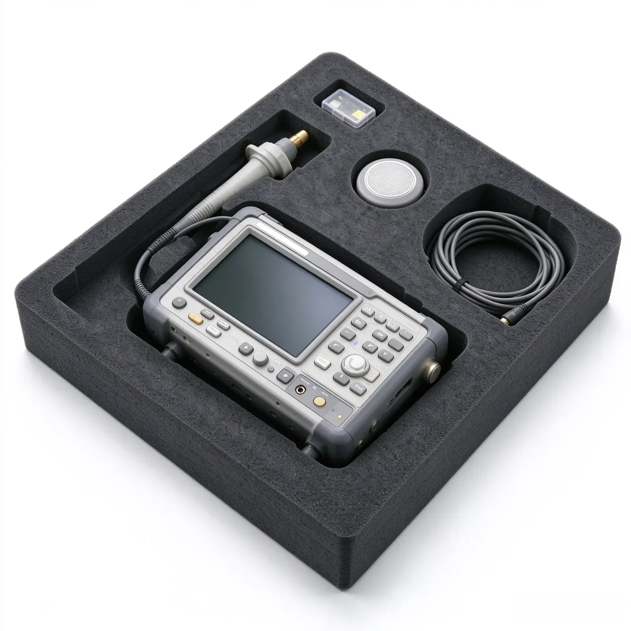
Depth is read with a dial indicator on a surface plate, zeroed on the surrounding face; length comes from a caliper across the band, both on the card with the cavity number. The reject line for injection-molded case sink marks reads: a sink deeper than 0.15 mm or longer than 8 mm fails appearance. That line governs looks, not stiffness, and dark resin shows a stronger band, so dark parts are judged on Grade A.
5. Locking the Process Window
The window behind injection-molded case sink marks is not proven by one trial; it has to be written so the next shift can reproduce it. The centre is 225 degrees C melt, 45 degrees C mould, 42 MPa pack and 18 s cooling, with one step of margin either side. Edges are found one factor at a time, until the mark goes over the line or the part shorts, then stepping back; four factors give a box, and a narrow box warns that cooling is weak.
A lot change on injection-molded case sink marks means re-qualifying. Melt flow rate can shift 10 percent within one grade, and a faster lot needs a shorter pack or the near gate overpacks while the far end starves. The locked window lives on a card taped to the machine; any change is logged with a reason.
Conclusion
Control order for injection-molded case sink marks is geometry first, process second: a 0.53 rib ratio holds the depression near 10 microns, 42 MPa in three stages over 3.5 s feeds shrinkage before gate freeze, and 18 s at 45 degrees C keeps distortion inside 0.1 mm. Lose one and the reading returns above 0.15 mm. Writing the window onto the card beats finding it again at every trial.
Related Reading
- Rib Design Principles for Cases
- How Case Reinforcement Ribs Are Placed
- How to Set Case Wall Thickness
- Case Mold Building Standards
Related Products
- 8 Series — Gun Cases; Military Equipment Cases; Camera Equipment Cases; Drone Cases; Watch Cases; Knife Cases; First Aid Cases; Electronics Equipment Cases
- WL8-2812 PP Gun Case — model WL8-2812
- All protective cases and toolboxes: 7 series, 158 models