

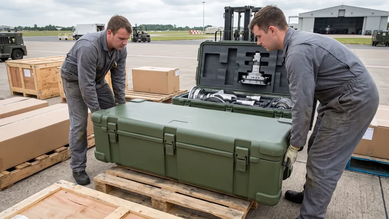
Quick answer: Military Controller Protective Case uses a 6 mm conductive foam and 8 mm shield lap to hold lid diagonal drift within 2 mm after a 1.2 m drop.
Table of contents
- How the Military Controller Protective Case Reinforces a Panel Cut-Out
- Conductive Foam and the Twin-Lip Seal Overlap
- What Drives Lid Diagonal Drift
- Salt Spray and Stack-Load Test Sequence
- Clearance Control of the Self-Locking Hinge
- FAQ
1. How the Military Controller Protective Case Reinforces a Panel Cut-Out
A Military Controller Protective Case is 660×470×290 mm outside, 590×400×225 mm inside, 4.5 mm wall, 8.1 kg empty, 16 kg payload. A cut-out breaks the lid rim and pulls closing force to the corners. A folded flange restores 4.5 mm locally and closes the load band. Long-side ribs match that wall; short sides use rounded corners. Four 460 N latches feed force through the frame into the twin-lip seal. JUNZHIJIA records frame flatness and flange thickness at one station.
Treat the frame of a Military Controller Protective Case as the datum and shielding shares one landing with sealing. Flatness drift leaves foam over-pressed in spots and barely touching in others.
| Cut-out zone | Reinforcement | Logged value |
|---|---|---|
| Long-edge flange | Same-mould fold-back | Wall 4.5 mm |
| Short-edge corner | Stress spread | Rounded transition |
| Frame corners | Rib alignment | Flatness record |
| Latch seats | Four positions | 460 N each |
2. Conductive Foam and the Twin-Lip Seal Overlap
On a Military Controller Protective Case the 6 mm conductive foam sits inside the frame, the twin-lip seal outside, both looping the opening. Shielding needs the pressed foam touching lid and base at once; the ≥8 mm lap is the width meeting the lid conductive layer, not the pressed thickness. Six millimetres is free height, closing to about 4 mm, leaving rebound so a 1.2 m drop does not pull the lap under 8 mm. Two lips, one inboard one outboard, leave a cavity for foam travel. The 460 N clamp spreads across the frame then splits between foam and seal, checked per segment with a feeler gauge.
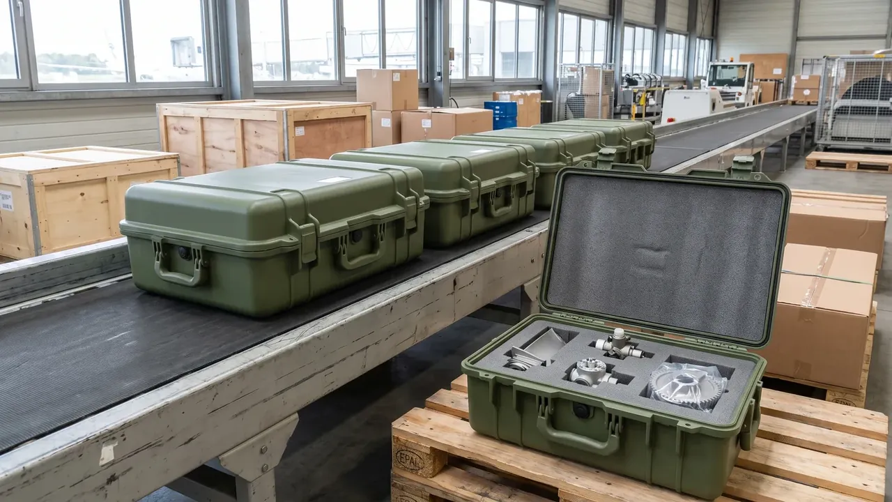
When the lap falls short on a Military Controller Protective Case, the shield parts first at the opening corners, where diagonal drift grows fastest. Logging ≥8 mm per side beats one figure on a drawing.
| Shielding stage | Material and position | Logged value |
|---|---|---|
| Conductive foam | In-frame 6 mm | About 4 mm pressed |
| Overlap width | To lid conductive layer | ≥8 mm |
| Inner lip | Outboard rim | Moisture block |
| Outer lip | Outboard rim | Salt-spray block |
3. What Drives Lid Diagonal Drift
The ≤2 mm diagonal drift of a Military Controller Protective Case is re-read after a 1.2 m drop; its cause is the cut-out splitting the lid into two bands of unequal stiffness. The long side has the frame, the short side only a flange, so the two rebound out of step and the lid twists along its diagonal. Past 2 mm the foam retreats from the corners and one seal lip loses pressure. The plant drops over corner, edge and face in three rounds, reading both diagonals each time and taking the difference.
A −30 °C to 60 °C span magnifies this for a Military Controller Protective Case: cold stiffens the foam, heat softens the lips, so both ends get a diagonal reading before the thermal share fits the ≤2 mm window. IP66 is judged last, only while lap and diagonal hold.
| Overlap reading | Measurement point | Judged item |
|---|---|---|
| ≥8 mm | Static closed | Four sides logged |
| ≥8 mm | Post-drop recheck | Corner retreat |
| ≤2 mm | Diagonal difference | Lid twist |
| 6 mm | Foam free height | Rebound margin |
4. Salt Spray and Stack-Load Test Sequence
A Military Controller Protective Case runs 96 h salt spray and 3-layer stacking on one lot, since either alone misses frame fatigue. Neutral mist runs 96 h first to see whether the outer lip and flange corrode into a channel; the lot is then stacked 3 layers so the lower lid bears load and the foam is checked for lost rebound. The ≥8 mm lap and ≤2 mm diagonal are re-read at the end and must match pre-test figures.

Spray comes before stacking on a Military Controller Protective Case; reversed, packed foam absorbs mist and the reading cannot split corrosion from creep. Both 96 h and 3 layers are benchmarked on the shell side, with no reference to how items sit inside. The 1.2 m drop is scheduled before the combined run so two damage modes never share one verdict.
5. Clearance Control of the Self-Locking Hinge
A Military Controller Protective Case holds its 90° open angle with a self-locking hinge sharing one insert group with the short frame edge. Clearance watches radial slack between pin and bush: too loose and the lid sags at 90°, pulling the lap off the corners; too tight and −30 °C makes opening bind. The plant reads bush clearance at room temperature and −30 °C, then checks the 90° stop for contact. The hinge governs posture only; clamp force still comes from the four latches.
Two items are logged here: bush clearance and 90° stop contact. Both must pass before lid posture is stable.
Conclusion
A Military Controller Protective Case treats the panel cut-out as a load band to close again: 660×470×290 mm outside and a 4.5 mm wall fix the datum, a folded frame, 6 mm foam and ≥8 mm lap carry shielding, and ≤2 mm diagonal after 1.2 m closes the chain. Spray at 96 h, 3-layer stacking and −30 °C to 60 °C fold drift onto one card, with IP66 judged only while lap and diagonal hold. Reading frame-to-lap-to-diagonal-to-recheck beats watching one rating. JUNZHIJIA keeps frame, press bench and drop recheck on one batch record.
Related Reading
- Electronic equipment case specification guide
- Protective case shell structure and inspection items
- Environmental test benchmarking for protective cases
- Cut-out and shielding design of equipment cases
Related Products
- 8 Series — Gun Cases; Military Equipment Cases; Camera Equipment Cases; Drone Cases; Watch Cases; Knife Cases; First Aid Cases; Electronics Equipment Cases
- WL8-2812 PP Gun Case — model WL8-2812
- All protective cases and toolboxes: 7 series, 158 models