

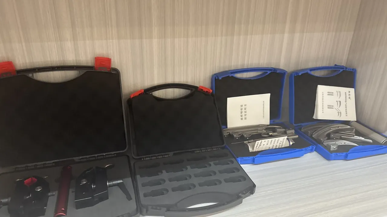
Quick answer: A Military Drone Transport Case starts from three numbers: 8 to 12 mm of clearance around the airframe, 15 mm at the top, a 5 mm rotomoulded PE wall, and four tie-down points rated 800 N each. Fix those first, and a 1.5 m drop and a 1.2 t stack become measurable questions rather than opinions.
Table of contents
- How the Cavity Is Zoned
- Support Pads and Limit Blocks
- Separating the Battery Bay
- Tie-Down, Lifting and Stack Loads
- Road, Air and Sea Add-Ons
- Sealing, Balance and Lid Opening
- FAQ
1. How the Cavity Is Zoned
A Military Drone Transport Case is divided by weight first and handling order second. For a four-rotor airframe the usual split is three zones: 55% for the body, 25% for batteries, 20% for blades and harness. The ratio is not cosmetic. It puts the loaded centre of gravity within 30 mm of the handle line, so the base does not tip up when one person lifts.
Clearance is set from the airframe outline: 8 to 12 mm on all four sides, 15 mm at the top. Under 8 mm the unit drags on the foam during loading; over 12 mm the foam no longer holds it, and a 2 mm shift in transit polishes a bright mark into the cavity wall within six months. Hold the internal height to ±1 mm, or two shells built to the same drawing end up with cavity depths that differ by 2 mm.
| Zone | Share of cavity volume | Shell-side provision |
|---|---|---|
| Airframe | 55% | base pad, corner limit blocks |
| Battery | 25% | separate walls, 10 mm vent gap |
| Blades and harness | 20% | 60 mm shallow tray, R3 mouth |
2. Support Pads and Limit Blocks
Pads cannot sit wherever the drawing looks tidy. The load paths run through the landing-gear mounts and the arm roots, four to six points in total. Pads bear on exactly those spots, in EVA at 30 kg/m³: one pad carries about 150 N at 10% compression, so four pads give 600 N, enough for an 8 kg airframe at three times dynamic load.
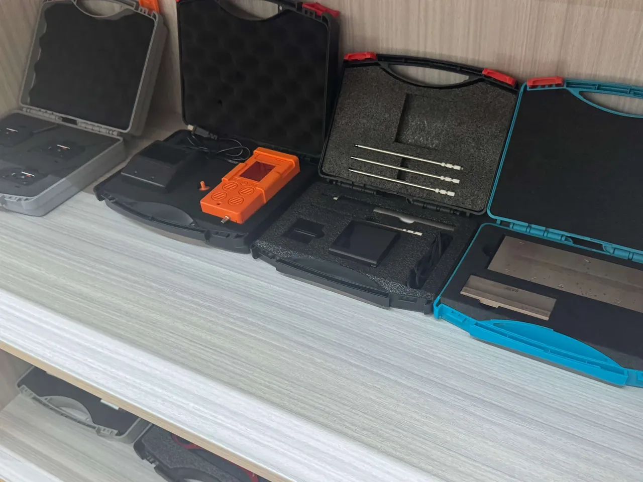
Set 1.5 mm of interference between pad and airframe, then add two 20 mm vertical ribs on the sides to stop lateral travel. Keep the four pads within 1 mm of each other in height. Past that, one corner of the airframe hangs free, the drop load lands on the diagonal pad alone, and that foam compacts and never returns to thickness, so the second drop has no cushion left.
Block position matters more than block hardness. A block bearing on the arm root lets the arm share lateral load; the same block moved to mid-arm doubles the moment arm and the same side force shears a slit through the foam. Measure the centre distance between arm roots, then place blocks at half that distance plus 5 mm.
3. Separating the Battery Bay
The battery bay has to be walled off from the airframe bay. The divider runs 15 mm thick and stands 10 mm taller than the bay floor, which forms a lip; leave a 10 mm vent gap between wall and battery, because a vehicle interior reaches 60℃ in summer and heat otherwise accumulates inside the cavity.
A glued divider alone will not hold. Cut two 3 mm locating grooves in the base, seat the divider, then bond it: the joint takes an extra 200 N in shear. With the case stood on end, the divider carries the full battery mass, and a failed bond drops the whole row rather than one unit.
Stagger the two bay depths as well. An airframe bay at 350 mm against a battery bay at 250 mm leaves a 100 mm step that houses the divider and the harness route. Equal depths look neater on a drawing but produce one continuous seam across the cavity, and moisture travels the full length of that seam.
4. Tie-Down, Lifting and Stack Loads
Four tie-down points sit on reinforced pads at mid-wall, 800 N each, 3.2 kN combined, which covers lateral inertia during a 1.2 t stack. Use 5 mm stainless rings set 12 mm deep, with a measured pull-out above 2 kN. A ring set into a plain wall without a pad will flare the wall into a trumpet shape before it lets go.
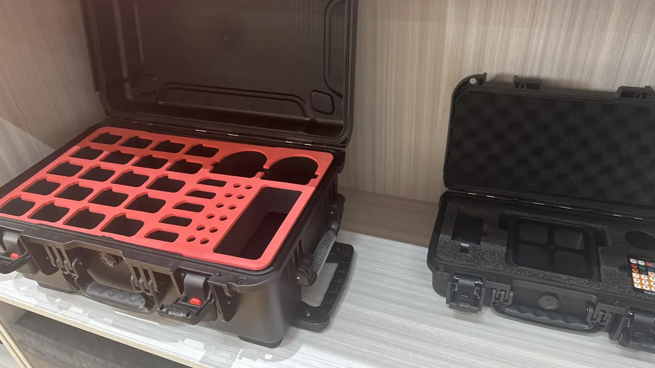
Lifting uses two points, both above the centre of gravity. An offset over 20 mm lifts one end first, drags the other across the floor and loads the slings unevenly. Lid strength comes from crown height: a 6 mm crown feeds stack load into the four walls, while a flat lid deflects 4 mm under 1.2 t and the gasket is drawn open along that deflection.
Leave 120 mm fork pockets in the base and cap the mouths with 2 mm stainless. Unprotected plastic mouths chip after repeated fork entry. Space the pockets symmetrically so the case lifts level, which is the single detail that keeps handling incidents out of a Military Drone Transport Case programme.
5. Road, Air and Sea Add-Ons
| Mode | Dominant load | Shell-side addition |
|---|---|---|
| Road | 5 to 200 Hz for 8 h | four base isolators, latch safety pins |
| Air | 0.5 bar differential, -40℃ | vent valve, low-temperature compound |
| Sea | 95% RH, 48 h salt spray | 70A gasket, 8 μm hardware plating |
Road accounts for most of the mileage and most of the failures. Floor unevenness turns a 3 mm step into a point load under the base; two 20 mm longitudinal ribs spread that load over 300 mm of length. Add a stainless safety pin at each latch and release in vibration effectively disappears.
Air freight needs its own arithmetic. Half a bar acting on a 0.54 m² lid equals 2.7 kN of lift, split between two latches at 1.35 kN each, which is why air-freight variants use a thickened latch keeper. Sea freight is judged on salt spray: no red rust after 48 hours of neutral spray, and plating below 8 μm will not hold that line.
6. Sealing, Balance and Lid Opening
Thirty percent gasket compression is the stable point: an 8 mm cord closed to 5.6 mm. Cycle the case five times between -30℃ and 60℃ and the cord should shift less than 5 Shore A while returning above 90% of its height. Groove dimensions of 3 mm deep by 6 mm wide, with the cord standing 5 mm proud, let a replacement cord drop in without reworking the mould.
Balance is read from the empty case. Keep the empty centre of gravity within 15 mm fore and aft and 10 mm vertically of the geometric centre; loaded, it shifts about 40 mm toward the battery bay, so the handle moves 25 mm the same way.
Lid attitude needs designing too. A 4 kg lid with two limiting straps, opening to 95° on a 260 mm strap, keeps hinge load near 60 N. Without straps the lid falls back and that load jumps to 300 N, which cracks the hinge pocket within a few uses. Stopping at 95° rather than 180° also lets the lid block crosswind on a coastal site instead of slamming shut.
Related Reading
- Specifying a military air transport case
- How a military air transport case is built
- Factors behind custom foam
- Running a batch incoming inspection
Related Products
- 8 Series — Gun Cases; Military Equipment Cases; Camera Equipment Cases; Drone Cases; Watch Cases; Knife Cases; First Aid Cases; Electronics Equipment Cases
- WL8-2812 PP Gun Case — model WL8-2812
- All protective cases and toolboxes: 7 series, 158 models