

Quick answer: A Military Supply Case specification is a chain, not a dimension table. A clause supplies load and temperature, the load becomes a moment, the moment fixes wall and rib pitch, and only then do tolerances reach the drawing.
Table of contents
- The Chain Starts With Three Clauses
- Turning Load Into Wall Thickness
- From Cavity to Outer Envelope
- Four Load Paths Through Latch, Hinge and Corner
- Tolerance Allocation and Measuring Points
- FAQ
1. The Chain Starts With Three Clauses
Drawings fail two ways: a full envelope with no traceable source, or one line claiming the case meets a military standard, which hands judgement back to the supplier. Neither has a starting point.
Start from clauses: MIL-STD-810H 516 for shock and vibration, 501 and 502 for storage from -46 °C to +71 °C, ASTM D4169 for stacking and a 1.2 m drop, IEC 60529 IP67 for 1 m immersion over 30 minutes.
| Source clause | Supplies | Fixes in the drawing |
|---|---|---|
| MIL-STD-810H 516 | Shock peaks, vibration spectrum | Corner buffer depth |
| MIL-STD-810H 501 and 502 | -46 °C to +71 °C | Resin grade, seal compound |
| ASTM D4169 | Stacking, 1.2 m drop | Base structure, minimum wall |
| IEC 60529 IP67 | 1 m immersion, 30 min | Seal groove width |
Every number on a Military Supply Case drawing then points to a clause, not a preference, so design and acceptance share units.
2. Turning Load Into Wall Thickness
Under stack load the side wall acts as a plate, not a beam: a simply supported strip of 400 mm span, the 135 kg lid load as a line load, deflection capped at span over 200, or 2 mm.
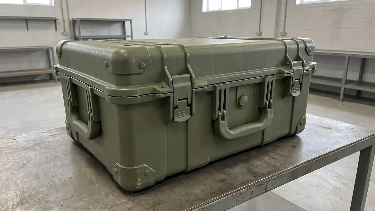
Back-calculating thickness needs bending modulus, span and deflection limit. HDPE copolymer measures about 900 MPa at 23 °C, putting the minimum wall at 5.2 mm; a 15 percent cold derating lifts the nominal value to 6.0 mm. The arithmetic is easy, the assumptions are not: temperature, load duration, creep factor, edge restraint. Omit one and a supplier moulds 4.5 mm. That is why a Military Supply Case wall is never an isolated figure, and why 6.0 mm behaves differently at -46 °C, where the plate sits near brittle fracture and creep grows past 30 percent.
| Location | Wall (mm) | Basis |
|---|---|---|
| Lid centre | 6.0 | Deflection under span over 200 |
| Side wall | 5.5 | Four-high stack, 135 kg top |
| Rib root | 3.5 | Draft angle, weld line |
| Corner buffer | 8.0 | 1.2 m corner drop |
Ribs sit at 120 mm pitch, three times the wall: tighter and weld lines merge into a crack origin, wider and a cold panel bulges until the lid leaks.
3. From Cavity to Outer Envelope
Cavity first, envelope second. A Military Supply Case cavity takes the largest item plus 20 mm per axis, plus-only tolerance, because a cavity is only moulded undersize.
The chain usually breaks at the corner cap, a second-operation part with a looser tolerance; folding it in stacks two tolerance sources. Keep the bare body on the drawing, the cap on its own line.
Shrinkage is written per direction: 1.9 percent along flow, 2.2 percent across, a gap that becomes 1.8 mm at each end of a 1200 mm body, enough to misalign the lid.
4. Four Load Paths Through Latch, Hinge and Corner
Impact energy on a Military Supply Case leaves by four paths, each with one group of parts and one value:
- Corner: cap and buffer ribs, 1.2 m corner drop, 25 mm radius
- Edge: flange and seal groove, 12 mm flange height
- Panel centre: rib grid, 2 mm maximum deflection at 120 mm pitch
- Latch: retention only, 4.5 N·m tightening torque
Treating the latch as a structural member is the commonest misjudgement. The nylon hook goes brittle in the cold, and once it carries impact the break starts at the hook root, the one place that cannot be thickened.
The hinge pin runs 6 mm with 0.2 mm clearance: below 0.1 mm it seizes in the cold, above 0.3 mm the lid rocks and works the seal.
5. Tolerance Allocation and Measuring Points
Tolerances should not be spread evenly. Group by function: mating features such as the lid interface and seal groove take plus or minus 0.3 mm, assembly 0.8 mm, envelope 2 mm.
Measuring points belong on the drawing: twelve wall points at long-edge midpoints, R25 corners and rib roots, three flatness points with a 300 mm straight edge, six groove widths on a projector. Verify in order: dimensions, 96 hours of salt spray, then the 1.2 m drop.
Conclusion
A Military Supply Case specification is a closed loop: clause supplies load, load becomes moment, moment fixes wall, and the wall splits force between latch and corner. Delivery turns on the link that never breaks, not the thickest wall, which is why a Military Supply Case sheet is a chain.
This article discusses only the container (case body) side of specifications and design intent, and does not cover any handling, loading or use of the contents.
Related Reading
- Material, colour and marking layers
- Acceptance: appearance, sealing and drop
- Scene configuration for transport
- Specification logic of a flight case
Related Products
- 8 Series — Gun Cases; Military Equipment Cases; Camera Equipment Cases; Drone Cases; Watch Cases; Knife Cases; First Aid Cases; Electronics Equipment Cases
- WL8-2812 PP Gun Case — model WL8-2812
- All protective cases and toolboxes: 7 series, 158 models