

When an optical fiber preform line is relocated, the outcome rarely hinges on the drawing tower itself, which may stand twenty or thirty metres tall. It hinges on the parts inside that tower: the nozzles and dies of the multi-stage heating zones, the high-alumina insulation shells exposed to temperatures above 2000 degrees Celsius, the tower shell sections ten metres and longer, and the payoff reels spinning at line speeds that can pass 2000 metres per minute. The glass core of the fiber is only nine microns across, so a single local bend beyond the minimum radius of curvature reduces the strength of a whole five kilometre spool at one point, and it fails later in a cascade during drawing or testing. The environment compounds this. Radiant heat from the hot zones bakes the tower shell, humidity leaves residual vapour that condenses as the metal cools, and particulate plus static discharge at unpacking act directly on the glass surface. Inside the cleanroom all of this is handled by the process. Once the machine is broken into pieces, crated and moved by road or sea, the protections that the machine carried with it no longer exist.
The principle we therefore apply is deliberately specific: JUNZHIJIA does not put a drawing tower and a payoff reel into a case. JUNZHIJIA treats hot-zone precision parts, tower shell sections, high-speed rotating parts and finished fiber as four different objects, each with its own compartment architecture, its own cushioning physics and its own acceptance criteria. The approach below has been applied to tower relocation and spare-parts turnover on several running lines, and it maps directly onto shop drawings.
Table of Contents
- Stress Sensitivity of 9 Micron Glass Filament in Transit
- Precision Compartments for Zone Moulds and Nozzles
- Sectioned Packing for Tall Tower Bodies and Flange Datums
- Shaped Cages for Multi-Zone Insulation and Thermal Mass
- Payoff Reel Runout and Spindle Seating
- Maintaining Coil End Flatness Through Handling
- Transport Locking of the Tension Control Mechanism
- Humidity-Induced Tensile Strength Loss in Glass
- Particulate and Static Suppression for Cleanroom Startup
- Winder Station Resonance and Microbending Risk
- Vibration Spectra and Stack Limits for Shell Sections
- Site Acceptance: Fiber Strength and Tower Plumb
- Compartment Classes and Packing List Discipline
- Frequently Asked Questions FAQ
- Conclusion and Related Reading
Stress Sensitivity of 9 Micron Glass Filament in Transit
Fiber protection logic differs from metal protection logic in kind. Metal fails by fatigue; glass fails by strength loss. The criterion is not peak stress at one point but the accumulation of flaw density along the whole length. A nine micron core carries a tensile strength in the three to five gigapascal range, yet one surface scratch a micrometre or two deep can drop that to under a third of the original. Three damage sources dominate in transit: hard retainer hardware pressing into the filament, particles grinding the glass repeatedly under vibration, and cyclic variation of winding tension that accumulates microbending loss.
| Failure mode | Trigger | Protection measure | Acceptance criterion |
|---|---|---|---|
| --- | --- | --- | --- |
| Retainer crushing | Hard reel edge part contacts the glass | Full-perimeter EPE edge ring covering the flange width | No marks on the flange; rebound above 30% |
| Particle grinding | Particles above 50 microns present during vibration | Clear window for visual check; fiber sealed before casing | No particulate in the bag; spool lifts out intact |
| Layer microbending | Winding tension cycling through vibration | Spool locked on a dedicated spindle frame | Clearance below 8%; displacement under 3mm |
Our approach is that finished fiber never enters the main case body. The spool is finalized on the winding machine inside the manufacturer's cleanroom, its end face conditioned, then sealed in three layers: an antistatic polyethylene bag at 0.08 to 0.1mm film thickness with a surface resistance between 10^9 and 10^11 ohms, an aluminium foil laminate as the vapour and mechanical barrier, and a rigid cylindrical outer shroud. The sealed assembly is backfilled with dry nitrogen at a dew point below minus 40 degrees Celsius. Only then does it enter a dedicated compartment, and that compartment contains no foam at all. Foam rubbing glass in vibration is actively harmful, so the compartment limits rather than cushions: low-friction expanded polypropylene rings hold the sealed spool with 2 to 3mm of circumferential clearance.
The controlling specification is vibration against displacement, and relative movement must stay under 3mm, because once the end face is knocked out of position the layer pattern is destroyed and unwinding tension at restart spikes, breaking filament from the innermost layers. The approach is shared with precision instrument protective cases, but stricter, because fiber tolerates no residual movement at all.
Precision Compartments for Zone Moulds and Nozzles
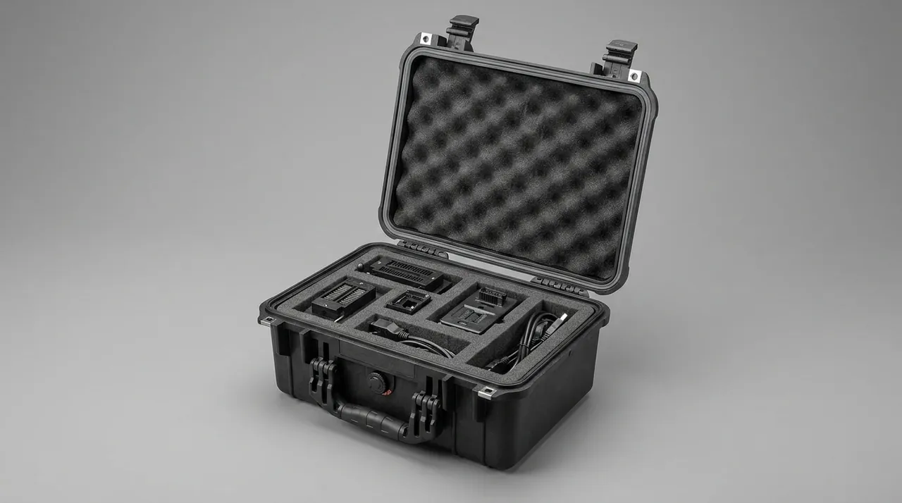
The draw nozzle and the die are the two most failure-prone parts in the tower. Nozzles run continuously at 2000 to 2200 degrees Celsius and are commonly made of tungsten, molybdenum or ceramic matrix composites. Dies are smaller again, with an internal bore measured in micrometres to tens of micrometres. While installed, neither needs much protection, because the furnace atmosphere and rigid location already do the work. The moment they are drawn from the hot zone for shipment they enter an entirely different state. A tungsten nozzle heated above 500 degrees Celsius oxidises violently in air. A ceramic die fractures under thermal shock. A bore a few micrometres across is permanently scrap the moment one particle lands inside it.
Nozzles and dies therefore travel in independent precision compartments, never alongside tower shell sections:
| Item | General compartment | Precision nozzle and die compartment |
|---|---|---|
| --- | --- | --- |
| Liner material | Flat EPE foam | Moulded closed-cell EVA at 90kg/m3 or higher |
| Location method | Bagged or wrapped | Location pins plus retaining ring, bore upward |
| Environment | Ambient, impact protection | Double moisture barrier plus two desiccant packs |
| Temperature requirement | None | No heat source above 40 degrees Celsius for 48 hours before casing |
| Packing attitude | Free | Specified orientation with anti-rotation spigots |
| Acceptance method | Visual | Visual plus 10x borescope plus a go-gauge check |
Volumetric utilisation in these compartments is deliberately held between 40 and 50 percent, the remaining space going to cushioning. The failure mode here is single-impact scrap, so we would rather add foam than allow one millimetre of movement under transport load. The cavity walls are lined with black closed-cell foam, which absorbs shock and prevents parts from rubbing together and generating metal debris.
One process detail is routinely overlooked. A part drawn while still hot and sealed immediately creates a closed high-temperature micro-environment, and on cooling vapour condenses on the part surface. Every precision compartment must therefore pass through a forced cool-down to ambient with no residual heat confirmed, and 48 hours is the practical window. Comparable compartment logic is described under glass mould cases.
Sectioned Packing for Tall Tower Bodies and Flange Datums
A complete optical fiber drawing tower may stand twenty to thirty metres, well beyond the height limit of a normal road vehicle. The practical answer is to section the tower in three to six metre lengths at the fabrication or modification stage and bolt or flange them together on site. That creates a new problem: a sectioned tower has no global stiffness and cannot keep itself plumb, while the drawing datum between the nozzle centreline and the payoff centreline decides whether a nine micron fiber can be drawn at all.
Keeping the plumb line true follows three paths, and the case is responsible for the third: the machine side, where the foundation and anchor bolts establish intrinsic accuracy; the tooling side, where the transfer trolley and adjustable legs handle movement inside the plant; and the packaging side, where compartment supports and flange face protection preserve that accuracy in transit.
For long sections we use a locating skeleton with four-sided constraint. The liner is not laid foam. A coaxial sizing steel spine runs through the shell section and is tightened against the case shell by adjustable supports, forming a four or six point constraint. The section changes from a thin-walled pipe that can bend into a short column restrained at both ends, and plumb and coaxial deviations are locked at the packing stage.
Flange faces need their own protection. Once a flange face is dented, bolts cannot be preloaded evenly on reassembly, the tower picks up additional bending, and drawing tension varies directly into fiber strength. Each flange therefore carries an independent end cap with a soft interlayer, so no hard material ever stacks against the sealing face. Coaxiality records and flange flatness reports travel in the same compartment so site reassembly has a reference.
Shaped Cages for Multi-Zone Insulation and Thermal Mass
The multi-stage heating zone is built from concentric shells whose inner wall temperatures step through 1200 to 2200 degrees Celsius, wrapped externally in layers of high-alumina ceramic fibre blanket, mullite fibre modules or insulating brick. These shells have two defining characteristics. Their thermal mass is very large, so heating and especially cooling take tens of hours. And once wetted, the blanket permanently loses both strength and thermal performance, because ceramic fibre attacked by water will powder at the first touch.
Thermal mass and transport pull in opposite directions. The shell must be cooled for a long period before packing, but every hour of cooling raises the humidity inside it, and sealing it while damp guarantees condensation. The packaging has to solve moisture and compression at the same time:
| Insulation form | Packing method | Controlling point |
|---|---|---|
| --- | --- | --- |
| Ceramic fibre blanket rolls | Sleeved in a moisture barrier bag inside a shaped cage | Two desiccant packs; cage limits volume loss to 15% |
| Mullite fibre modules | Laid into rigid divided cells | 5mm rebound allowance per layer; separator sheet between modules |
| Insulating brick masonry | Dry fill plus rigid baffles | No wet fill; no free movement in brick joints |
| Outer metal jacket | Separate thin-plate compartment | 20mm air gap between jacket and insulation body |
The shaped cage is the decisive component. Left unconstrained, ceramic fibre blanket settles to under 60 percent of its original volume during transport vibration, arriving as a collapsed waste product even though it looked full when packed. The cage is a galvanised steel skeleton welded to the shell diameter and wrapped in a moisture barrier film, holding volume change within 15 percent. The 20mm air gap matters equally: direct metal-to-fibre contact lets vibration abrade the blanket into powder, and the gap also serves as thermal insulation so external heat in transit does not preheat the interior.
Payoff Reel Runout and Spindle Seating
The payoff reel is the fastest rotating component on the line. At a winding speed above 2000 metres per minute the spool runs at several hundred revolutions per minute. Three mechanical consequences follow, and all three must be immobilised at the packing stage.
First, spindle runout. If the fit between spindle and bearing seat has clearance, the periodic runout at this speed is amplified into tension spikes. The remedy on site is to replace or refit the bearing, and a bearing assembly is expensive enough that one distortion in transit becomes an irreversible loss. The bearing seat therefore sits in its own cavity with a face-retaining pad, and the cavity length is aligned to the spindle axis so the journal carries no side load for the whole journey.
Second, spool sway. A large reel, commonly 600 to 800mm in diameter, carries a large and eccentric mass when full. Any free clearance lets the spool strike the cavity wall during vibration, and repeated impacts collapse the end face. The liner is therefore a conical locating element matched to the spool cone, axially locked between an end cover and a thrust block, and radially supported on three or four arc pads that remove play. Clearance is held within 1.5mm per side: tight enough to prevent rattle, loose enough to avoid squeezing.
Third, flange guards and the traverser. Traverser guide wheels are commonly engineering plastic or small-diameter metal parts, and any burr scores the glass. The traverser is caged separately, its wheel shafts held by soft clamps rather than rigid locks.
| Part | Risk | Compartment design | Acceptance check |
|---|---|---|---|
| --- | --- | --- | --- |
| Spindle and bearing seat | Distortion causing runout and tension spikes | Concentric cavity with face-retaining pads | Coaxiality within 0.5mm; no indentation |
| Spool body | Sway impacting the cavity wall | Conical locating liner with bidirectional thrust | Single-side clearance within 1.5mm |
| Flange guard and retainer | Hard edge crushing the fiber | Full-perimeter EPE with radiused transitions | No marks on the flange |
| Traverser guide wheel | Burrs scoring fiber, shaft bending | Separate small cavity with soft clamps | No burrs; no play when turned by hand |
General protective practice for rotating components of this kind is covered under industrial equipment parts cases.
Maintaining Coil End Flatness Through Handling
The coil end face is a quiet pain point on a drawing line. A freshly wound spool has an orderly face that operators rely on to locate the strand and unwind smoothly. Once that face is crushed out of pattern in transit, the layers collapse, and every pass of the strand over the flange edge rubs and overlaps itself. The result is fiber breakage at the unwind station or a scrapped spool.
Flange flatness rests on three control points:
| Control point | How it is destroyed | Protective design |
|---|---|---|
| --- | --- | --- |
| Flange edge regularity | Retainer hardware pressed into the winding layers | Full-perimeter EPE edge ring with locating collar, thicker than any flange protrusion |
| Layer restraint | Vibration permitting layers to slide | Twin conical locating surfaces plus a face equaliser plate spreading pressure across the whole face |
| Upper and lower faces | Stack load transferred into the coil face | Equaliser plates above and below, with soft interlayers |
The equaliser plate is the item most often skipped. In a stack, the mass of the case above passes through the liner down to the coil. If the liner happens to place a hard point or a void directly over the end face, load concentrates on the outermost winding and leaves an indentation. The whole face area must therefore be supported by a continuous flat soft layer whose compression matches the load above, spreading pressure across the face instead of at a few points.
Face inspection on arrival is quick. Viewed against a light, the layer boundaries should read as one continuous spiral. Visible step layering, a depression or a local collapse means transport loading exceeded the design limit. The check appears on our acceptance checklist and inside the site three-stage verification.
Transport Locking of the Tension Control Mechanism
Tension control is the core of fiber strength uniformity. The system normally comprises load cells, servo drives, encoders, PI control boards and a tension swing arm, all working on dynamic tension signals between roughly 0.3 and 5 newtons with measurement accuracy near 0.05 newtons. These parts rarely fail in transit by being dropped; they fail by zero drift and calibration loss. Load cell elastic bodies under sustained load do not fully recover, so residual stress redistributes and the zero point shifts. Encoder discs can move relative to their gratings. Precision components and connectors develop intermittent contact faults, the hardest kind to chase on site.
The mechanism therefore travels in a constrained electronics compartment. Each load cell is sealed in an antistatic bag filled with conductive foam that dissipates charge and provides restraint, closed with a sealing clip so charge cannot escape during transit. Servo drives and control boards stay in their factory antistatic boxes, wrapped in 30mm EPE. Moving parts such as the swing arm use a half-lock strategy, held at the calibrated position without excessive preload, so vibration cannot accumulate residual stress at the lock point. The compartment forms a rigidised bay with walls at least 15mm thick, supported by expanded polypropylene at 60 to 80kg/m3 density so it is decoupled from the case shell. This adds a requirement that antistatic protective case practice does not cover: not only preventing discharge, but keeping calibration, so the part needs no recalibration or has a defined datum.
Humidity-Induced Tensile Strength Loss in Glass
Optical fiber absorbs no moisture, yet it is highly sensitive to water. The mechanism is not absorption but ionic exchange at the glass surface: hydrogen ions in adsorbed water exchange with sodium ions in the glass network, forming a sodium hydrogenosilicate layer that partially dissolves the surface and creates a stress corrosion site. Fiber strength falls with time in humid conditions, and that fall is irreversible once the part is dried again.
In a drawing line, humidity reaches the fiber along three paths:
| Path | Mechanism | Control |
|---|---|---|
| --- | --- | --- |
| Finished fiber exposed to humidity | Surface ionic exchange reducing strength | Three-layer sealing plus nitrogen plus dew point below minus 40 degrees Celsius |
| Coating hydrolysis | Acrylate coating hydrolyses in humid heat, weakening layer adhesion | Keep humidity and temperature from coexisting at high values |
| Residual vapour in the machine | Tower cools after shutdown and condensation forms | Dry displacement before casing; dew point verified before sealing |
All three paths are governed by dew point, not relative humidity. Relative humidity shifts with temperature: as a case cools from 40 to 20 degrees Celsius, moisture content may be unchanged while relative humidity climbs from 20 to 60 percent, well outside the control band. A humidity indicator card inside the case is therefore a useful arrival tool, but the actual control is the combination of nitrogen backfill and desiccant.
Desiccant quantity is calculated from cavity volume and intended storage duration, not added by guesswork. A commonly used figure is 100 to 150 grams per cubic metre per 30 days of molecular sieve or calcium chloride, with two indicator cards placed at the top and the bottom of the cavity. Vapour settles low, so a card at the top alone gives a flattering reading. Long ocean routes get an intermediate check, and spools stored in humid regions sit under external monitoring as described in warehouse stacking and moisture cases.
Particulate and Static Suppression for Cleanroom Startup
The cleanliness requirement for fiber is frequently underestimated. With a nine micron core, a five micron particle that lands on the surface can no longer be removed by the cleaning and coating steps that follow, and it surfaces months later as a break or a strength defect. Every tower component must therefore receive its final cleaning in a cleanroom before casing, and the compartment interior has to reach the corresponding cleanliness level.
Particulate control rests on three things. Compartment walls use closed-cell foam, which does not shed, unlike open-cell material. Every part is wiped and vacuumed before insertion, and the insertion itself is performed entirely inside the cleanroom. The case must be thoroughly cleaned after its last use, especially in the recesses, the hinge seats and the latch pockets, which is where particles hide.
Static control matters just as much. Unpacking in dry conditions can generate several kilovolts of separation charge between case and liner, and that discharge lands on floating dust. Glass is an excellent insulator: charge accumulates on the surface instead of dissipating as it would on metal, and acts directly on the filament, creating a breakdown point during drawing or downstream testing.
| Stage | Static source | Suppression |
|---|---|---|
| --- | --- | --- |
| Packing | Separation and friction | Conductive foam liner with a bonded grounding strap |
| Transport | Continuous triboelectric charging | Internal metal parts bonded to the case; discharge aperture |
| Unpacking | Gasket peel | Equalise pressure before opening, touch the aperture first |
| Line start | Friction of glass over guides | Hold the cleanroom between 40 and 60 percent RH |
Configuration detail is covered under cleanroom equipment cases and optical lens coating cases, where low-shedding and static suppression are treated in depth.
Winder Station Resonance and Microbending Risk
Many people assume a case only matters during transport, but half of the vibration problem on a drawing tower is generated at the machine itself, and it is influenced by decisions taken during packaging design. A winder running at 2000 metres per minute produces continuous high-frequency vibration, and where its base is rigidly connected to the floor that vibration travels through the tower foundation and moves the draw point.
The important observation is that a drawing tower tolerates slow micro-movement far better than it tolerates high-frequency resonance. Between the nozzle and the payoff, the glass travels several to more than ten metres. If any structural member in that span has a natural frequency close to the excitation frequency from the winder, the filament picks up a periodic lateral disturbance that accumulates into microbending loss. This damage is invisible at final test. The macrobend test may pass, yet the attenuation peak pair in the water peak region shows abnormal broadening.
| Observation | Likely frequency source | Protection or corrective action |
|---|---|---|
| --- | --- | --- |
| Constant tremor in the winder foundation | Motor imbalance, insufficient base stiffness | Inertia base plus elastic pads under the machine |
| Periodic micro-sway of the tower | Rigid connection between tower base and floor | Vibration isolation trench and pads at the tower base |
| High-frequency flutter of guide wheels | Worn wheel bearings, pulsating strand tension | Replace bearings and close the tension control loop |
| Case or packaging resonance | Case or liner natural frequency inside the excitation band | Damped liner design, avoid a single foam thickness |
The case contributes here by refusing to amplify the problem. Sites frequently report that equipment behaves correctly after installation yet fails an incoming transport test once packed, because a case or liner resonance falls inside the excitation band and amplifies vibration through its walls. When we simulate transport vibration for these lines, the winder base frequency of roughly 30 to 60Hz is swept together with the case natural frequency, and the liner material is adjusted for damping to suit.
Vibration Spectra and Stack Limits for Shell Sections
A tower shell and a payoff reel are both heavy, large and frequency-sensitive, so the choice of transport condition drives the packaging configuration directly. On a road-dominated route, excitation is random road input with most of its energy between 5 and 80Hz. On a long ocean route, vessel sway and roll add content between 0.5 and 3Hz. The two bands act on the components through different mechanisms:
- The high band, 5 to 80Hz, acts on slender parts and readily excites local bending modes. This is the main threat to shell sections and insulation assemblies.
- The low band, 0.5 to 3Hz, acts on heavy masses and produces gross displacement and spool sway. This is the main threat to the payoff reel.
The two categories of part therefore need different cushioning logic and cannot share one parameter set.
| Part | Main excitation band | Cushioning strategy | Stack limit |
|---|---|---|---|
| --- | --- | --- | --- |
| Tower shell section | 5 to 80Hz local bending | Coaxial sizing skeleton plus sidewall EPE at 40mm or thicker | 2 tiers |
| Insulation assembly | 5 to 40Hz | Shaped cage constraint plus isolation pads | 2 tiers |
| Payoff reel | 0.5 to 3Hz sway | Conical locating surfaces plus full-face equaliser base | No stacking |
| Nozzle and die cavity | 20 to 100Hz high-frequency impact | High-density moulded closed-cell EVA liner | 2 tiers |
| Sealed fiber cylinder | Full band | Three-layer sealing with rigid location and no foam | No stacking |
Payoff reels are excluded from stacking for a specific reason. The reel's load capacity is governed by the spindle and bearing fit, and load from the case above reaches the spindle through the coil face. The concentrated load at the bearing inner race far exceeds the face-averaged pressure. Once that exceeds rating, the race deforms, and the reel runs with runout and rising temperature on arrival even though the exterior looks undamaged. Reel cases are therefore marked on the side as no stacking and no load above, and a dedicated spindle frame is supplied for site transfer.
Test basis: whole-case performance may reference the ISTA series, domestic transport may reference the GB/T 4857 series, and distribution cycles may reference ASTM D4169. Test conditions belong in the purchase technical agreement with named items, severity levels and criteria, where the criteria cover not only that the case does not break but that internal parts do not move, fiber is undamaged and the coil face shows no step layering.
Site Acceptance: Fiber Strength and Tower Plumb
The value of arrival acceptance lies in distinguishing transport damage from handling damage, so it must run in a fixed sequence and produce records.
Step one, inspect before opening. Record the case exterior, latch condition, humidity indicator reading if the card is visible through a window, any water marks and any evidence of resealing. Photograph everything.
Step two, open in sequence. Equalise pressure through the relief aperture first, confirm there is no residual pressure, then dismantle layer by layer in the specified order so the upper sections cannot fall out as the lid clears.
Step three, verify compartment by compartment against the packing list, with particular attention to:
| Compartment | Acceptance action | Criterion |
|---|---|---|
| --- | --- | --- |
| Sealed fiber cylinder | Inspect bag integrity and read the dew point card | Bag intact and airtight, card within limit |
| Nozzle and die cavity | Inspect bore and faces under 10x magnification | No oxidation, no chipping, no adhering particles |
| Tower shell section | Measure coaxiality across both ends and overall length | Coaxiality within 1mm over full height |
| Payoff reel | Turn the spool by hand, inspect shaft and edge guard | Rotates smoothly, no noise, no axial free play |
| Coil end face | View the face against a light for layer continuity | Continuous layers, no stepping or depression |
| Tension compartment | Inspect load cells and drive units, recalibrate if required | Zero and calibration still inside original validity |
| Insulation assembly | Inspect shaped cage and fibre volume | Volume loss within 15%, no powdering |
Step four, record and close the loop. Anything found is photographed on arrival and compared against the packing record to establish whether damage happened in transport or during handling. Nonconformances are recorded and notified to the shipper rather than absorbed on site. Unpacking results, the removed fixture list and any outstanding issues are returned to the packing party as input for the next batch.
Oversize items such as the tower add one further consistency check. After the sections are rejoined on site, re-measure the plumb line and the relative position of the nozzle centreline to the payoff centreline. That measurement is the final proof that packing precision survived the journey.
Compartment Classes and Packing List Discipline
The previous sections cover how to protect. This one covers how to organise: a packing scheme spanning dozens of compartments will fail on site if the organisation itself is muddled.
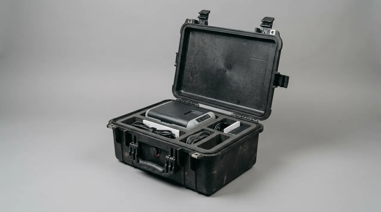
The division rule sorts components by the consequence of failure and their transport sensitivity. Class A covers high-value precision parts that are scrap on impact and unrepairable on site, namely nozzles, dies, bearings and load cells. Class B covers large structural parts such as shell sections, insulation assemblies and shaped cages. Class C covers consumables and auxiliaries including seals, heating elements, terminals and tools. Class A items each get their own compartment and ship first. Class B items may share a case but must be individually located. Class C items fill the remaining volume as secondary cushioning.
The packing sequence follows heavy parts at the bottom, precision parts at the top, and fiber spools in the upper middle. Large heavy items sit low, with payoff reels in their own case or on the lowest independent support. Precision compartments go high so the mass of stacked cases above is not transferred down onto delicate parts. Sealed fiber cylinders sit in the upper middle so lifting never loads them.
The packing list is not a name list; it must support reverse operation on site. Every line carries a compartment code, part name and drawing number, quantity, individual sealing method, inspection datum, mandatory arrival check and a fragile flag. Cavity labels inside the case must match the list, and identification uses both compartment code and colour, because colour remains readable in glare and dust where print may fail, and colour provides redundancy when a label is lost.
| Field | Purpose |
|---|---|
| --- | --- |
| Compartment code | Links drawing, list and site record |
| Part name and drawing number | Prevents fitting a superseded revision |
| Individual sealing method | Parts needed on line can be used without reopening |
| Inspection datum | Source of the quantified arrival criterion |
| Mandatory arrival check | Prevents omission of a critical check |
| Fragile flag | Signals extra care at opening |
| Cleanliness grade | Marks the clean-sealed state of fiber-related cavities |
Parts intended for direct line start, such as spare nozzles or spare load cells, are marked keep sealed during customisation so only the outer protection is stripped on site and the inner barrier is never opened. The wider customisation sequence is set out in instrument case selection guidance.
Frequently Asked Questions FAQ
Q: What is the most fundamental difference between an optical fiber drawing tower case and an ordinary equipment case?
A: The fundamental difference lies in the failure criterion. An ordinary equipment case targets an intact shell and no part displacement, which is a macroscopic judgement. Drawing tower components behave differently: nozzles and dies are single-impact scrap that cannot be rebuilt on site, glass filament suffers hidden strength loss without visible damage, and a crushed coil end face costs a whole spool. All three are low-probability, high-consequence events in transit. Design therefore shifts from shell impact resistance toward compartment isolation, finely tuned cushioning and traceable in-transit state. At JUNZHIJIA we build a failure mode list first and work backwards to the case structure. That is why compartments are divided by consequence of failure rather than by size, why precision parts occupy cavities at 40 to 50 percent volumetric utilisation, why fiber is triple sealed instead of foamed, and why every cavity carries its own arrival criterion. Case strength matters far less than knowing which item must not move at all, and which item must never be unpacked on site at all.
Q: What principles should govern where a drawing tower is sectioned for transport?
A: Three considerations must be balanced. First, transport limits: a single section must satisfy the loading height and width of the chosen transport mode, which for road haulage usually means 3 to 6 metres. Second, structural stiffness: each section must not deform elliptically beyond recovery under its own weight and transport vibration, so the flange section must have a considerably higher second moment of area than the shell centre. Third, reassembly accuracy: every extra joint adds tolerance, so section count should be minimised. Site conditions matter too, since section boundaries should land on existing floor openings, doorways or lifting access. Our packaging planning requests the tower general arrangement and the site lifting constraints, then develops the sectioning scheme together with the cavity layout so that no joint is placed where reassembly is hardest to lift. The rule of thumb is that sectioning is a joint decision between the mechanical designer, the site rigger and the case engineer, never a packaging decision made after the fact. Where a shell has already been sectioned, the packing list must also record which sections are matched neighbours, since a joint between two non-adjacent sections cannot be checked for coaxiality on arrival.
Q: Why can a payoff reel not simply be packed like other equipment, and what needs attention in transit?
A: The reel's character comes from four factors stacking up: large diameter, large mass, an eccentric centre of gravity and high-speed dynamic operation. Eccentricity is first. A full spool is far heavier on one side, and if single-side clearance in the case exceeds 1.5mm, vibration drives the spool into repeated wall impacts, and the accumulation collapses the coil face. Bearing load is second. The spindle and bearing seat tolerate far less than the face-averaged pressure, so stack load concentrated at the inner race can deform the race and produce runout and temperature rise on arrival. Flange crushing is third. Edge retainers and guards touch the glass directly, and any indentation is irreversible. The answer is a conical locating liner matched to the spool, bidirectional axial thrust locking, a full-perimeter EPE edge ring with radiused transitions, and a no-stacking mark on the side. Add a fourth point about the packing list: the reel weight and its centre of gravity offset have to be declared, because a crate that looks within limits at the fleet level can still be unbalanced at the pallet. For movement around the plant, use the supplied spindle frame rather than shuttling the case repeatedly on a pallet truck.
Q: Why is foam cushioning not used around finished fiber during packing?
A: Foam is a contaminating medium around glass. Expanded foams rub continuously against the filament during vibration, producing two effects: friction varies cyclically and adds directly to strand tension, creating tension pulsation; and foam particles and fibres shed onto the glass surface, where they interfere with the cleaning and coating steps that a nine micron core demands. The correct approach is triple sealing. An antistatic polyethylene bag at 0.08 to 0.1mm provides antistatic protection and a first barrier, an aluminium foil laminate provides the vapour and mechanical barrier, and a rigid cylindrical shroud resists crushing. The sealed unit is backfilled with dry nitrogen held below minus 40 degrees Celsius dew point. The compartment then contains no foam at all; location is achieved with low-friction expanded polypropylene rings leaving 2 to 3mm of circumferential clearance, so the sealed cylinder barely moves in transport. One consequence worth noting is that a foam-free compartment cannot be tuned by adding material, so the locating ring geometry has to be right the first time and verified on a trial spool before the batch is built. Foam belongs in the neighbouring precision compartments, where the parts are metal and tolerate aggressive cleaning.
Q: Where should humidity indicator cards sit inside the case, and how often should they be read?
A: Position matters, and placing a card casually at the bottom produces an optimistic reading. Vapour is lighter than air but condenses in the lower part of the cavity as temperature falls, so one card belongs at the top and one at the bottom. The difference between the two readings is itself diagnostic: if the lower card reaches its end-of-life colour first, condensation is occurring locally, usually because dry displacement before sealing was incomplete or the case has been wet. Inspection frequency follows the route and the climate. Domestic road moves need only an arrival check. Export sea freight warrants a check about one month after loading and again on arrival; tropical routes or summer shipments warrant a fortnightly review. The cards remain a fast check rather than a control: the real control is the nitrogen backfill together with desiccant dosed by calculation, at 100 to 150 grams per cubic metre per 30 days, not by eye. Record the readings on the packing list as well, so that a card found to have travelled can be traced back to which cavity it belonged to.
Q: What protection rating should a drawing tower case have, and is IP67 necessary?
A: A full IP67 rating on every case is not necessary, and the sensible approach is rating differentiation by compartment. Shell sections and insulation assemblies are large structures with no immersion exposure, so IP65 as defined by IEC 60529 and GB/T 4208, meaning dust tight plus protection against water jets, normally satisfies domestic road and general ocean routes. Three compartments do warrant more. The nozzle and die cavity reaches IP67 or adds an independent moisture barrier, since one ingress event destroys the part. The sealed fiber cavity, already protected by an inner barrier bag, should also sit at no less than IP67 to handle long ocean condensation and accidental immersion. The tension control electronics bay needs at least IP65 plus antistatic bags so condensation cannot short the boards. The reel cavity is judged mainly on dust exclusion and mechanical impact. One further point: the IP rating is a property of the whole case system, decided by shell, gasket, latch and pressure equalisation valve together, not by any single component in isolation.
Q: How long after removal from the hot zone can a nozzle or die be packed?
A: The process requirement is that it must cool to ambient with residual heat confirmed absent before entering a precision sealed compartment, and 48 hours is the window we recommend. This step is routinely skipped and is the most frequent cause of nozzle protection failures. A nozzle drawn at operating temperature can exceed 800 degrees Celsius internally; sealed immediately, it creates a closed hot micro-environment in which airborne vapour condenses into a film on the part. For tungsten and molybdenum nozzles that film accelerates oxidation on the next heat-up, and for ceramic dies vapour can enter microcracks and become a stress source. Polymers in the packaging may also release volatile material onto the hot part surface. The correct sequence is: draw the part, cool naturally to ambient in the cleanroom, wipe and vacuum the surface, measure and record part temperature before it enters the precision compartment, then complete dry displacement inside the cavity before sealing. Record the temperature, because it is the only evidence that the cool-down was verified rather than assumed by the operator who closed the lid.
Q: Which documents should accompany the case so that site acceptance can be carried out?
A: Seven document groups earn their place in the handover file. First, the compartment packing list with compartment code, part name and drawing number, quantity, sealing method, fragile flag and a colour identification cross-reference. Second, drawings: the case outline drawing with the internal compartment layout and the key positioning dimensions. Third, inspection and test records, covering the whole-case transport test report with its route and criteria under ISTA, GB/T 4857 or ASTM D4169, the sealing rating declaration, and the dew point record taken when the fiber cylinders were sealed. Fourth, the arrival acceptance checklist with quantified criteria such as coaxiality within 1mm over full tower height, reel clearance within 1.5mm per side and continuous coil face layers. Fifth, the environment control record stating desiccant quantities and card placement. Sixth, the declaration of conformity and traceability number, so shipper and consignee share one numbering logic. Seventh, the nonconformance and feedback form that closes findings back into the packing process. Organisation practice is illustrated in optical fiber equipment cases.
Conclusion and Related Reading
Transport protection for a drawing tower rebuilds heat-zone, cleanliness and precision protection once the machine leaves the cleanroom. JUNZHIJIA divides compartments by failure consequence, matches cushioning to frequency band, and accepts sealing on dew point, with custom liners, OEM/ODM and handover documentation from Kexin New Materials (Guangdong) Co., Ltd.
Related Reading