

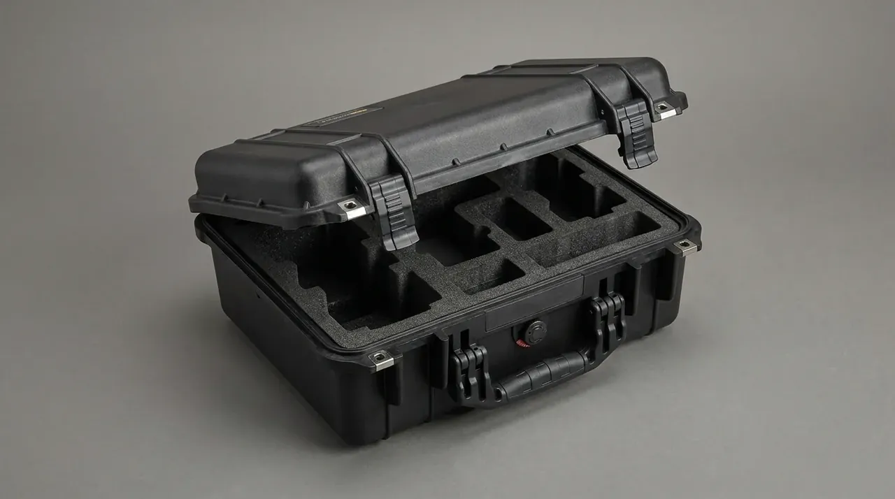
Quick answer: A power line drone case holds 15–25 °C with a 25 mm wall, 500 g of phase change material and a 15 W heater, clearing the cold lockout in 20 minutes.
Table of contents
- Why the Battery Bay Holds 15–25 °C
- How 500 g of PCM and a 15 W Heater Split the Work
- The 25 mm Wall Build
- Twenty Minutes at −20 °C
- Metal Parts Under a 220 kV Field
- FAQ
1. Why the Battery Bay Holds 15–25 °C
On a winter morning at the tower base, six packs come out of the van at −18 °C. At that temperature internal resistance sits 40% above its 25 °C value and the same pack delivers 65% of rated capacity. Closing that gap is the first job of the bay.
The upper limit is just as real. Thirty days at 45 °C costs 8% of usable capacity against 2% at 25 °C, and every 10 K above the sweet spot roughly halves calendar life. The wall has to block a −20 °C morning and a 60 °C afternoon in a parked van.
Ten kelvin is narrow, so the packs get their own bay.
| Ambient band | Bay start temperature | Warm-up needed | Heater duty | Hold above 15 ℃ |
|---|---|---|---|---|
| −20 ℃ | −18 ℃ | 20 min | 100% | 6.5 h |
| −10 ℃ | −9 ℃ | 11 min | 80% | 8 h |
| 0 ℃ | 0 ℃ | none | 0% | 10 h |
| 25 ℃ | 26 ℃ | none | 0% | 12 h |
| 45 ℃ | 48 ℃ | venting only | 0% | 9 h |
2. How 500 g of PCM and a 15 W Heater Split the Work
The heater lifts temperature; the phase change material holds it down. A 15 W pad between liner and packs runs on 12 V at 1.25 A and delivers 18 kJ in 20 minutes, while the PCM, charged on the previous shift, gives its latent heat back as it cools.
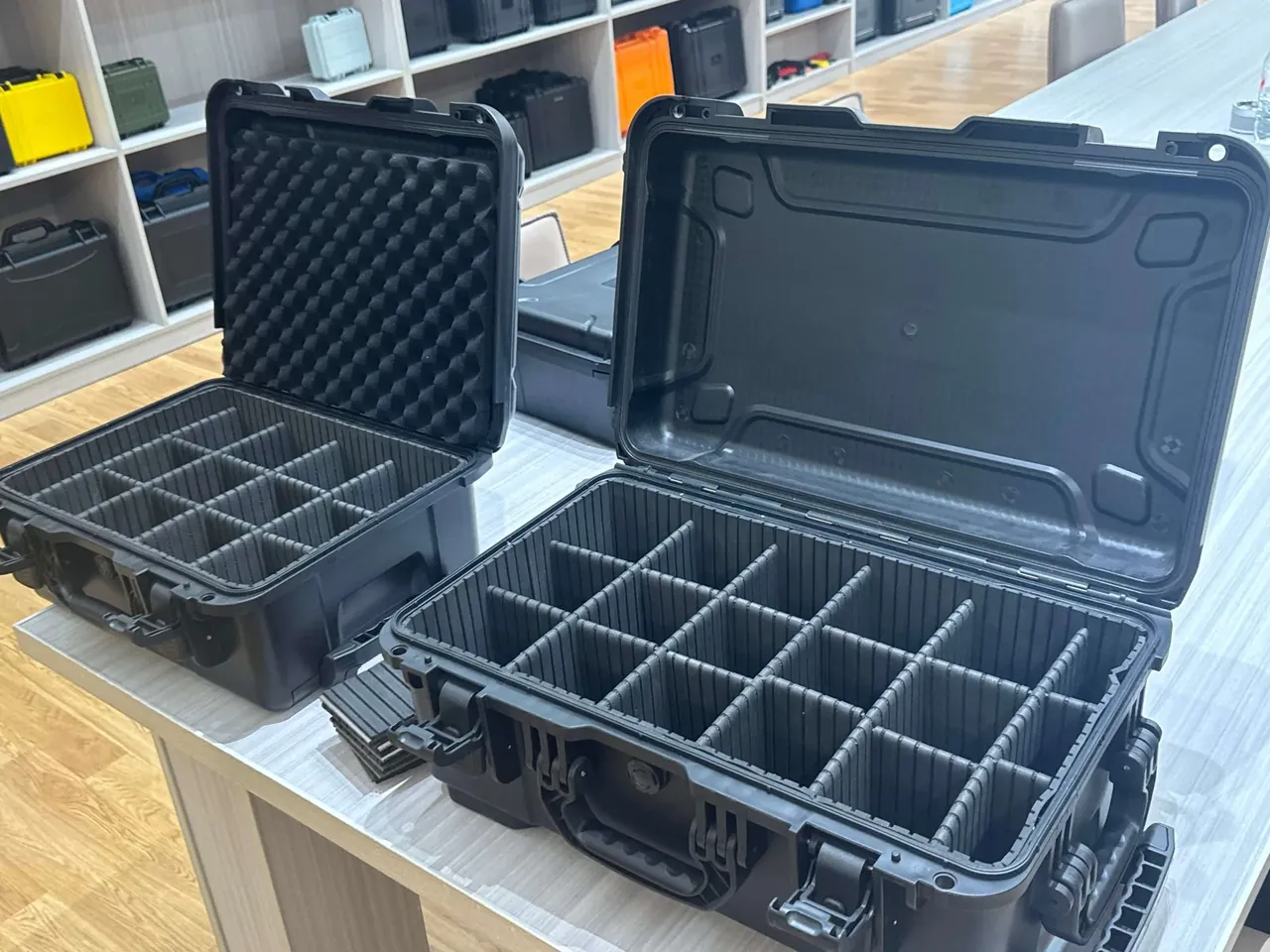
Five hundred grams of paraffin wax, melting at 22 ℃ with 190 kJ/kg latent heat, releases 95 kJ. With 7.2 kg of cells at 1.0 kJ/(kg·K) one kelvin costs 7.2 kJ, so the PCM lifts the bay 13 K and the heater adds 2.5 K: 16 K in total, a −20 °C start at about −4 ℃.
Sixteen kelvin does not reach 15 ℃. The 20 minutes exist to pull the packs out of cold lockout so the aircraft can launch; holding 15–25 °C for a full shift is the wall's job.
Where the PCM sits matters more than how much there is. Bonded to the liner 5 mm from the packs, heat arrives by radiation across a thin air layer; dropped in a corner 40 mm away, a third of it is absorbed by the wall.
| Bay zone | PCM mass | Gap to packs | Steady temperature |
|---|---|---|---|
| Under the pack cradle | 180 g | 5 mm | 21 ℃ |
| Lid interior | 140 g | 8 mm | 19 ℃ |
| Side wall sandwich | 100 g | 5 mm | 20 ℃ |
| Divider between packs | 80 g | 6 mm | 18 ℃ |
3. The 25 mm Wall Build
Twenty-five millimetres is three layers: 3 mm modified-PP shell, 18 mm polyurethane foam, 4 mm cross-linked PE liner. At 0.024 W/(m·K) the foam gives about 0.75 m²·K/W, and the assembly lands near 0.9 m²·K/W.
That sets how long the bay survives a power cut. With 20 ℃ inside, −20 ℃ outside and 1.35 m² of wall, heat flow starts near 60 W and narrows, so after 8 h the interior reads 12 ℃. Cut the foam to 10 mm and it drops below 10 ℃ in 4 h.
Thickness is not the whole story. Wet foam moves from 0.024 to 0.04 W/(m·K), loses 40% of its resistance and cuts hold time from 8 h to 4.5 h, so the shell seals the outside and no bare foam edge is left inside.
Thirty-five millimetres buys 0.3 m²·K/W and 1.5 h, at 12% of volume and 8 s per changeover.
4. Twenty Minutes at −20 °C
The bottleneck is not heater power but whether heat stays in. Fifteen watts against 1.35 m² of wall and a 40 K difference leaks through any 20 mm of insulation left unclosed, and that leak can eat half the heater output.
The second limit is conduction inside the packs. Six packs with 6 mm gaps let warm air climb the slots, and by the end of warm-up the spread is about 5 K. Narrow the gaps to 2 mm and it grows to 11 K, the top pack at 0 ℃ while the bottom sits at −9 ℃.
Heater output follows ambient: 15 W at −20 ℃, 12 W at −10 ℃, off at 0 ℃. Held flat in a −5 ℃ morning, the bay climbs to 35 ℃ in 40 minutes, harder on the cells than the cold.
Lid openings during warm-up must be rationed. Each one exchanges about 30% of the warm air and drops the bay 4 K; closing the gap takes 3 minutes, so two openings inside 20 minutes waste 6.
5. Metal Parts Under a 220 kV Field
At 220 kV the metal fittings become field concentrators. Sharp corners on latches, hinges and screw heads can see three times the field of a flat surface, so the case keeps only countersunk screws, sunk 3 mm and capped, swaps latches for PA66 with 30% glass fibre, and rounds the hinge pin to R2.
Metal is placed and shaped, not banned: the shielded leads of the sensing probes are wrapped in 0.2 mm copper foil with 10 mm of overlap at each end onto a 6 mm earth stud, tightened to 2 N·m and measured at 0.3 Ω.
Logging is the other half. A recorder inside the lid covers −40 to 85 ℃ at ±0.5 ℃, samples once a minute and holds 30000 entries, enough for 20 days unattended. Data leaves through a 12 mm waterproof connector.
Conclusion
Holding 15–25 °C is a fight against 40 K of ambient difference: a 25 mm three-layer wall keeps heat flow near 60 W, 500 g of phase change material stores a 95 kJ buffer, and a 15 W pad covers the last 2.5 K. Together they clear cold lockout in 20 minutes at −20 ℃ and stay above 12 ℃ across an 8 h shift. The metal treatment and the logger are what let a power line drone case work under 220 kV and still show its numbers.
Related Reading
- Battery bay and arm retention in drone transport cases
- Enclosure layouts for grid inspection equipment
- Compartment design for power inspection instruments
- A selection guide for utility protective cases
Related Products
- 8 Series — Gun Cases; Military Equipment Cases; Camera Equipment Cases; Drone Cases; Watch Cases; Knife Cases; First Aid Cases; Electronics Equipment Cases
- WL8-2812 PP Gun Case — model WL8-2812
- All protective cases and toolboxes: 7 series, 158 models