

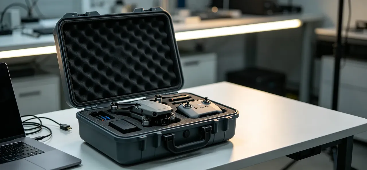
Quick answer: A drone transport case needs one bay per pack: a 169×58×48 mm pocket for a 165×55×45 mm 6S 22000 mAh cell plus 20 mm of air to the frame.
Table of contents
- Why the battery bay needs its own wall
- Pocket size for a 6S pack
- The 20 mm gap and the base pad
- Lid angle and one-handed access
- Axial stops for folded arms
- FAQ
1. Why the battery bay needs its own wall
After one 1.2 m corner drop, three packs came out with a 0.6 mm dent on the end face, each lined up with a divider edge. A shared divider bows 4 mm inward at impact and presses onto the aluminium end cap, which yields 0.3 mm.
Span sets the bow: a 240 mm bay bows 6.5 mm, a 72 mm bay bows 1.4 mm, because deflection follows the cube of the span.
| Layout | Bay span | Divider bow | Pack out | Packs |
|---|---|---|---|---|
| Open tray | 240 mm | 6.5 mm | 8 s | Retired |
| Three bays | 110 mm | 2.8 mm | 11 s | 2–3 |
| Six bays | 72 mm | 1.4 mm | 14 s | 4–6 |
Bay count follows pack count. Four packs in four bays give a 96 mm span and 2.1 mm of bow; forced into three bays, one spans 140 mm, bow returns to 3.6 mm, and the dent comes back.
2. Pocket size for a 6S pack
A 6S 22000 mAh pack measures 165×55×45 mm bare and 168×57×47 mm with tab covers, at 2.7 kg. Cut the pocket at 169×58×48 mm with 1 mm a side, so fingers grip the sides and the pack lifts out without scuffing foam.
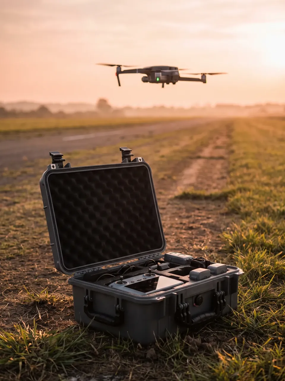
One millimetre is a floor, not a target. Below 0.6 mm the ±0.5 mm cutting tolerance eats the clearance; above 1.5 mm the pack slides 3 mm sideways and rubs the cover through.
The pocket floor is not flat: a 6 mm finger scoop sits at one end, so the pack lifts one-handed without pulling the tabs.
| Pack | Bare | With covers | Clearance | Mass | |
|---|---|---|---|---|---|
| 6S 22000 mAh | 165×55×45 mm | 168×57×47 mm | 169×58×48 mm | 1 mm | 2.7 kg |
| 6S 16000 mAh | 155×52×42 mm | 158×54×44 mm | 159×55×45 mm | 1 mm | 2.1 kg |
Depth is cut at 50 mm, 2 mm over the pack, to compress the 8 mm lid foam to 6.5 mm and clamp the top face.
3. The 20 mm gap and the base pad
Between battery bay and airframe bay sit 20 mm of still air. The airframe bay reaches 48 ℃ on its wall after long runs, and 20 mm of still air is worth about 0.6 m²·K/W, holding the bay wall under 35 ℃. Four 8 mm nylon pillars keep the gap open.
The pocket floor carries a 5 mm pad of 30 kg/m³ EVA. A 1.2 m fall lands at 4.85 m/s, and 5 mm of pad stretches braking to 10 mm, holding peak acceleration near 240 g; at 2 mm the peak climbs to 590 g and the bottom terminal fails first.
| Layer | Thickness | Material | Job |
|---|---|---|---|
| Base pad | 5 mm | EVA, 30 kg/m³ | Spreads 240 g over 10 mm |
| Air gap | 20 mm | Still air | Blocks 48 ℃ from the frame bay |
| Bay wall | 4 mm | Modified PP | Carries divider bending |
| Probe hole | 3.2 mm | Bore with sleeve | Puts the sensor on the skin |
Pillar spacing is 120 mm. At 180 mm the 4 mm wall bows 0.7 mm at 48 ℃, cutting the gap to 19.3 mm; below 90 mm the pillars block the pocket mouth.
The probe hole is drilled 12 mm above the pocket floor, 3.2 mm across, away from the land where the lid gasket presses. Its tip stands 0.5 mm off the skin, which reads 6 ℃ above cavity air.
4. Lid angle and one-handed access
At 120° the lid inner face sits 30° off horizontal and the wrist drops vertically onto the pack. At 95° the face stands upright and lifting one pack goes from 4 s to 9 s.
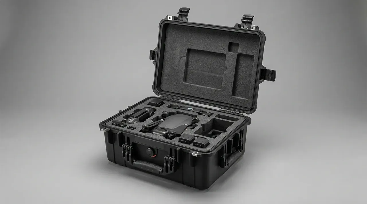
Two 15 mm webbing straps hold 120°, not hinge friction: each is riveted inside lid and body at 95 mm centres. Hinge damping stiffens below 5 ℃ to a 30 N opening force, which a gloved hand cannot manage.
At 120° the centre of gravity stays inboard of the hinge, with 40% overturning margin at 0.4 friction — needed, because field benches are often aluminium extrusion at 0.25.
5. Axial stops for folded arms
Folded against the body, each arm keeps 7 mm of axial freedom. Vibration from 5–200 Hz uses all of it, and after 40 hours the blade grip shows a polished band.
Stops are 30 kg/m³ EVA, 24 mm free height pressed to 22 mm, so 2 mm of interference equals 8.3% compression. Over a 1200 mm² face that is 6 N of rebound, enough to hold the arm without marking the carbon tube; past 3 mm the force jumps to 14 N and transverse lines appear.
The 2 mm includes 0.6 mm of compensation. The same foam takes a 4% set after 40 cycles, losing 0.96 mm, which still leaves 1.04 mm; with no allowance the stop becomes a spacer by the 60th cycle.
Bond stops to the slot end face, never the side: on the end face the load runs parallel to the glue at 0.35 MPa shear, on the side it becomes peel and lifts within 20 cycles.
Each arm gets two stops, at the root and 60 mm out. With only the root stop the tip swings 4 mm and the grip-to-wall clearance drops from 12 mm to 8 mm.
Conclusion
Fix bay geometry on the drawing, not in the foam shop after the first sample. Cut pockets at 169×58×48 mm with 1 mm a side, hold the 20 mm gap on four 8 mm pillars at 120 mm spacing, put a 5 mm pad of 30 kg/m³ EVA under each pocket, set lid straps at 95 mm for 120°, and press 24 mm arm stops down to 22 mm. Those six numbers are the purchase list: pocket size, pillar, pad, strap, stop height, interference. Before releasing the order, measure the cover thickness of three packs, take the largest, and add 2 mm. Anything estimated instead of measured leaves a mark on the pack face or the arm after 40 hours of transport.
This article discusses container-side specifications and design implications only, and does not cover any handling, loading or use of the contents.
Related Reading
- Drone case structure and model selection
- EVA and EPE custom foam inserts
- Battery bays in drone battery cases
- Heat and cell separation in high-rate battery cases
Related Products
- 8 Series — Gun Cases; Military Equipment Cases; Camera Equipment Cases; Drone Cases; Watch Cases; Knife Cases; First Aid Cases; Electronics Equipment Cases
- WL8-2812 PP Gun Case — model WL8-2812
- All protective cases and toolboxes: 7 series, 158 models