

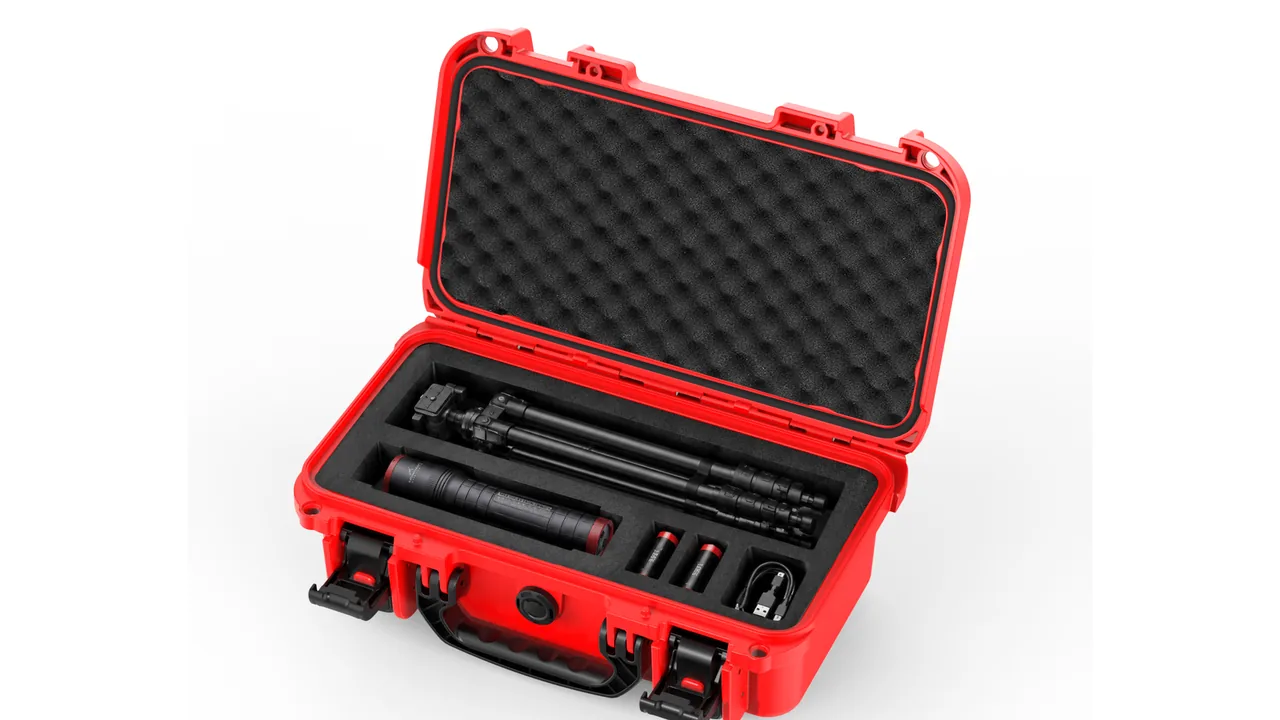
Take a protective case apart and it is two systems stacked: the shell delivers stiffness, sealing and stacking strength, while the liner delivers location, cushioning and energy absorption. Designed separately, the result is a very strong box that still delivers damaged equipment. JUNZHIJIA holds one principle across every complete case programme: the liner and the shell must be designed to a single load path, because shell stiffness decides how shock enters and liner structure decides how energy is dissipated, and both must converge under the same three constraints of volume, weight and preload.
Selecting a foam insert case means answering four questions: which liner structure to use, whether pick-and-pluck, solid contoured, layered pads or a divider hybrid; how much clearance and preload to leave; how much volume and weight to trade for cushioning stroke; and how long the configuration stays valid. This article starts from the shell and liner mechanism, then works through the structural families, fit parameters, weight and volume trade-offs, internal environment control and replacement strategy, ending with a selection checklist that can be applied directly.
Table of Contents
- How the Liner Works with the Shell: From Stiffness to Load Path
- Liner Structure Families: Pick-and-Pluck, Solid Contoured, Layered Pads and Hybrids
- Pick-and-Pluck Limits and Secondary Processing
- Solid Contoured Liners: Cavity Accuracy and Volume Efficiency
- Layered Pads and Modular Build-Ups
- Divider and Foam Hybrids: When Dividers Belong Inside
- Clearance Control, Preload and Closed-State Verification
- Liner to Shell Interface: Interior Dimensions, Radii and Stacking Datum
- The Weight, Volume and Portability Triangle
- Sealing, Pressure Valves and Liner Breathability Inside the Case
- Replacement Intervals, Spares Strategy and Remanufacture
- Selection Checklist and Acceptance Points
- Frequently Asked Questions FAQ
- Conclusion and Related Reading
How the Liner Works with the Shell: From Stiffness to Load Path
To understand a liner, first understand how shock enters. When a loaded case drops from a forklift, the outer surface deforms locally at contact, the deformation travels as a stress wave through the shell, and passes into the payload through the liner. A stiffer shell deforms less locally but hands the liner a higher peak acceleration; a more compliant shell absorbs part of the energy yet may press its deformation straight into the liner.
Liner input is therefore not payload weight alone but also shell stiffness. Rotomoulded polyethylene shells have uniform wall thickness and high toughness, deform noticeably and absorb energy during a drop, and are relatively forgiving of cushioning stroke. Injection moulded shells are stiff and dimensionally accurate but hand more energy to the liner, so they need a thicker cushion layer. The two are compared in more depth in Rotomolded Cases.
| Shell type | Wall character | Drop behaviour | Demand on the liner |
|---|---|---|---|
| --- | --- | --- | --- |
| Rotomoulded polyethylene | 3–6 mm, uniform | Large recoverable deformation | Moderate cushion layer |
| Injection moulded polypropylene | 2–4 mm, ribbed | Small deformation, stiff | Thicker cushion layer |
| Aluminium case | 1–2 mm sheet plus extrusions | Permanent local denting | Corner reinforcement needed |
| Laminated flight case | 9–12 mm panel | Very stiff, minimal deformation | Liner carries nearly all cushioning |
The second stage is how the liner itself transmits force. It spreads load across the payload surface, so larger contact area means lower unit pressure and less local damage. This is why fit is more often underrated than thickness: a cavity contoured to a curved surface spreads load over a whole contact patch, whereas a cavity with only a few support points concentrates the same force into small patches.
The third stage is the payload itself: weak features such as lenses, displays and thin walls set the allowable contact pressure ceiling, and the final step is to work backwards from contact area times allowable pressure to cavity shape and material. The method is developed systematically in Cushion Liner Cases.
Liner Structure Families: Pick-and-Pluck, Solid Contoured, Layered Pads and Hybrids
Foam insert cases divide into four families, ordered here by structural freedom.
Pick-and-pluck is a solid block pre-cut into a square grid; the user tears out cells by hand to form a cavity. Freedom is maximal and no design work is needed, but the cavity is stepped, fits curved equipment poorly, and removed cells cannot be restored.
Solid contoured liners are cut to measured payload geometry, in one layer or laminated. Fit and cushioning control are the best available, but the configuration is fixed and changing payload means changing liner.
Layered pads stack flat sheets, each opened or left solid as required, and adapt to different payloads by changing layer order, thickness and opening position. They sit between the other two and suit families of similar equipment with size variation.
Hybrids combine contoured foam, movable dividers and removable pouches: foam protects the main item, dividers separate accessories, pouches hold cables. Hybrids are the most flexible in the field and the hardest to design well.
| Family | Configuration freedom | Fit | Change cost | Best for |
|---|---|---|---|---|
| --- | --- | --- | --- | --- |
| Pick-and-pluck | Very high | Low, stepped | None | Sampling, temporary layouts, frequent change |
| Solid contoured | None | High, curved surfaces | High, new tooling | Fixed payloads in volume |
| Layered pads | Medium | Medium | Low, swap layers | Similar payloads, differing sizes |
| Hybrid | High | Locally high | Medium | Main item plus many accessories |
The first question is not which is best but how often the layout changes: above three changes a year, pick-and-pluck or layered pads cost far less over the case life; with a layout stable for three years, solid contouring wins on protection and appearance. The same logic applies in Case Dividers Versus Foam.
Pick-and-Pluck Limits and Secondary Processing
Pick-and-pluck is often dismissed as a cheap stopgap, but its usable range is wider than most buyers assume. Knowing the limits is what makes it worth using.
The governing parameters are grid pitch and cut depth. Common pitches are 10, 15 and 20 mm: a finer grid gives a smoother outline but tears less cleanly and is more likely to take neighbouring cells with it. Cut depth is normally 80 to 90% of block thickness, leaving 10 to 20% as tear points; too shallow and cells will not come out, too deep and they shed in transit.
| Grid pitch | Outline detail | Tearing difficulty | Structural strength | Recommended use |
|---|---|---|---|---|
| --- | --- | --- | --- | --- |
| 10 mm | High | High, cells tear together | Low | Small precision items, shallow cavities |
| 15 mm | Medium | Medium | Medium | General tools and instruments |
| 20 mm | Low | Low | High | Large items, deep cavities, heavy loads |
Three weaknesses are structural: the stepped cavity cannot follow curved surfaces, so contact reduces to points; torn walls are fracture surfaces prone to crumbling under repeated removal; and once the base is torn thin, bottom stroke drops sharply and the payload can bottom out.
Secondary processing recovers much of the gap. Three practices are common: consolidate torn walls with foam-grade adhesive to stop crumbling; leave the bottom layer intact as a cushion pad; and add a 3 to 5 mm low-density facing between payload and cavity to fill the steps. Together they lift pick-and-pluck close to layered-pad performance at the cost of one manual operation. Full techniques are set out in Pick-and-Pluck Foam Cases.
Solid Contoured Liners: Cavity Accuracy and Volume Efficiency
Solid contouring gives the best protection, governed by two metrics: cavity accuracy and volume efficiency.
Accuracy governs fit and handling. Practice keeps cavity outline within 1.0 mm of measured payload geometry, relaxed to 1.5 mm on curved sections. Tighter is pointless because foam rebounds and creeps; looser produces local bridging or over-pressure. Wall verticality matters just as much, because a tilted wall on a deep cavity jams the item during removal.
Volume efficiency is cavity volume divided by total case interior volume, and shows how much of the interior the liner actually uses. Solid contoured liners typically land between 55 and 75%, the remainder being wall thickness, finger recesses and lid pad. A figure below the band signals wasted nesting; above it signals walls too thin to survive handling.
| Liner type | Cavity accuracy | Volume efficiency | Unit cost | Change cost |
|---|---|---|---|---|
| --- | --- | --- | --- | --- |
| Pick-and-pluck | ± grid pitch | 40–60% | Low | None |
| Layered pads | ±2.0 mm | 50–70% | Medium | Low |
| Solid contoured | ±1.0 mm | 55–75% | Medium to high | High |
| Hybrid | ±1.5 mm | 60–80% | High | Medium |
Wall thickness is the other rule: at least 8 mm between adjacent cavities and 12 mm where depth exceeds 60 mm, since thin walls survive the first drop and crack on the tenth. Where several items share a case, high-frequency items belong on the top layer or nearest the opening.
Layered Pads and Modular Build-Ups
Layered pads let one liner serve a family of equipment rather than a single item. The interior is sliced horizontally into sheets, each opened or left solid, and different payload combinations are accommodated by changing layer order, thickness and opening position.
Inter-layer location is critical, because sheets that drift in transit no longer line up. Three methods exist: an interference fit of 1 to 2 mm against the interior, cleanest but demanding tight tolerance; locating pins or posts, most reliable but adding parts; hook-and-loop or double-sided tape, most flexible but short lived.
| Location method | Reliability | Ease of change | Interior tolerance demand | Service life |
|---|---|---|---|---|
| --- | --- | --- | --- | --- |
| Interference fit | Medium | High | High, about 1 mm | Long |
| Locating pins or posts | High | Medium | Low | Long |
| Hook-and-loop or tape | Low | Very high | Low | Short, needs renewal |
Layer thickness follows one rule: thick layers cushion, thin layers separate. A typical build is a 20 to 30 mm base pad as the main cushion, several 10 to 15 mm separator pads, and an 8 to 15 mm top pad. Stroke belongs at the bottom because the floor takes load first and the stroke is consumed most effectively from the bottom upward.
Modular build-ups extend the idea: the pad is cut into standard modules, each matching one item or accessory, assembled through a common interface. This pays off best where model count is high and volume per model is low, such as spare-part cases and demonstration kits. The penalty is discontinuous cushioning at the seams, which is handled by keeping a continuous cushion base layer beneath them.
Divider and Foam Hybrids: When Dividers Belong Inside
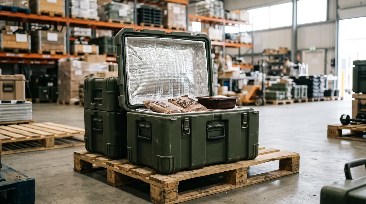
Foam excels at contouring and cushioning; dividers excel at separating and reconfiguring. Used together they cover cases neither handles alone.
The decision turns on two questions: whether items are regular in shape, and whether the layout must change often. Regular shapes that change often suit dividers; irregular shapes with protrusions and fixed layouts suit foam; everything between suits a hybrid.
Three layouts recur. Foam body plus divider accessory zone: the main item sits in contoured foam while accessories are separated by movable dividers. Divider frame with foam lining: dividers carry separation and load while 3 to 5 mm foam lining prevents slip and abrasion. Foam base with upper dividers: the base cushions while light accessories sit above in divider slots.
| Decision axis | Favours dividers | Favours foam | Hybrid answer |
|---|---|---|---|
| --- | --- | --- | --- |
| Item shape | Regular, square | Irregular, curved | Contoured body, divided accessories |
| Change frequency | High | Low | Fixed contoured plus variable divided |
| Item mass | Light to medium | Medium to heavy | Heavy contoured, light divided |
| Retrieval frequency | High | Low | High-frequency divided, low-frequency foam |
| Budget | Low | Medium | Contour critical areas only |
Divider reliability rests on the joints. Plug-in dividers engage slots in the shell, and slot depth should be at least 1.5 times divider thickness or they pull out under side load. Clip-on dividers use plastic clips whose fatigue life is the shortest element in the case and should be listed separately as spares. Structural detail is covered in Removable Divider Systems.
The failure mode specific to hybrids is stiffness discontinuity: the foam zone is compliant, the divider zone rigid, and if the boundary faces a drop corner, shock concentrates along it and tears foam or bends dividers. A transition strip of medium-density foam across the boundary solves it.
Clearance Control, Preload and Closed-State Verification
Clearance is the parameter most often ignored and most often responsible for failure. There are two kinds: fit clearance between payload and cavity, governed by interference; and free play in the closing direction, governed by preload.
Fit clearance comes from interference. Solid contoured liners take 0.5 to 1.5 mm per side, with clamping produced by foam compression. Pick-and-pluck needs 2 to 4 mm because the stepped cavity contacts poorly. Too little interference lets the payload shift and abrade; too much makes removal hard and accelerates foam fatigue.
Free play in the closing direction is removed by preload, defined as the percentage by which the lid pad compresses once the lid is shut, normally held between 20 and 30%. Preload restrains the payload vertically and prevents it from jumping and landing again inside the case, which is a second impact.
| Clearance parameter | Typical value | Too small | Too large |
|---|---|---|---|
| --- | --- | --- | --- |
| Cavity interference per side | 0.5–1.5 mm, pick-and-pluck 2–4 mm | Hard removal, tearing | Shift and abrasion |
| Lid pad preload | 20–30% | Lid will not close, latch overload | Vertical free play, second impact |
| Payload top to lid pad | 0–3 mm | Over-pressure, bulging | Vertical looseness |
| Liner to interior clearance | 0–1 mm | Hard assembly | Liner shifts as a whole |
Closed-state verification must be done with everything loaded, never on an empty case. Four checks apply: whether the lid latches without anyone pressing on it, since forcing it shut means preload is too high; whether latches show abnormal load, since a deformed tongue or a dull closing sound indicates overload; whether the side walls bulge, which means total liner thickness exceeds design; and whether the lid-to-base joint opens when the case is lifted by its handle, since an open joint compromises sealing.
One field rule covers most of it: with everything loaded, hold the case and shake gently, and nothing inside should make a sound, since any rattle means free play needing a shim or cavity correction.
Liner to Shell Interface: Interior Dimensions, Radii and Stacking Datum
A liner is not a standalone part; its outline must match the case interior precisely. If this interface fails, no amount of cavity design helps.
The first interface parameter is interior dimension. Published interior dimensions are nominal, and actual tolerance varies: rotomoulded parts can reach ±3 mm, injection moulded parts hold about ±1 mm. Liner outline should be designed to the lower limit, that is to the smallest interior the process can produce, so the tightest case still accepts it. Designing to nominal means a small case rejects the liner; making it far too small lets the whole liner shift in transit so cavities no longer line up.
| Interface parameter | Design value | Consequence of error |
|---|---|---|
| --- | --- | --- |
| Liner outline versus interior | 0–1 mm interference or line fit | Too large will not fit, too small shifts |
| Liner base radius | Match interior radius, R10 to R25 | Mismatch leaves the base floating |
| Total liner height | Interior clear height minus compressed lid pad | Excess prevents closing |
| Handle and latch clearance | Local slot or relief | Interference stops full closure |
| Stacking datum | Align with shell stacking features | Misalignment hurts stack stability |
The second parameter is corner radius. Case interiors carry radii, pronounced on rotomoulded parts, typically R15 to R25. A square-cornered liner floats on the corners once installed and bridges underneath. The correct approach is to chamfer to the measured radius or cut 45 degree reliefs at the liner corners, which matters most on deep cases because a floating base lets the whole liner sink.
The third parameter is the stacking datum. Stackable cases carry stacking load through the shell, and the liner should not carry it: the liner top surface must sit below the shell's stacking bearing face, otherwise the weight of the case above compresses the liner permanently over time. Stacking principles are set out in Stackable Toolbox Design Benefits and height limits in Stackable Toolbox Height Limits.
The Weight, Volume and Portability Triangle
The final constraint is that cushioning performance, case volume and total weight cannot all be optimised at once. Better cushioning needs thicker foam, thicker foam needs a bigger case, a bigger case is heavier and bulkier, and a heavier bulkier case generates more impact energy when dropped. It is a negative feedback loop.
Four routes break it. The first is cushioning efficiency: use the cushion curve to find the minimum thickness that satisfies fragility instead of adding thickness by habit, since moving from 40 mm to 32 mm often drops the case one size and total weight by more than 10%.
The second is zoned material. Vulnerable features usually account for only 20 to 30% of surface area, so high-performance thick foam belongs there and thin low-density foam, or nothing, everywhere else.
The third is mass distribution. Placing the heaviest item near the case centre and toward the handle does not change total weight but markedly improves handling and reduces the chance of tumbling during a drop.
The fourth is to accept a larger shell with a thinner liner. A bigger shell has a longer deformation stroke and absorbs more itself, which often makes it the best answer where vehicles or handling aids are available, though it fails for single-person carrying.
| Trade-off route | Cushioning | Case volume | Packed weight | Best for |
|---|---|---|---|---|
| --- | --- | --- | --- | --- |
| Thick liner, small case | High | Small | Medium | Single-person carry, tight space |
| Thin liner, large case | Medium to high | Large | Medium to large | Vehicle based, handling aids |
| Zoned efficient material | High | Small | Small | Precision, high-value payloads |
| Swappable layered pads | Medium | Medium | Medium | Several models sharing cases |
Material choice is also a weight variable. EVA runs 60 to 200 kg per cubic metre, EPP 20 to 100, IXPE 33 to 200. At equal cushioning performance EPP is typically 30 to 40% lighter than EVA, at higher cost and weaker contouring ability. Weight-critical applications such as carried communications cases should prioritise EPP or low-density IXPE. Material behaviour is compared in Protective Case Plastic Materials.
Sealing, Pressure Valves and Liner Breathability Inside the Case
Sealing performance and liner breathability pull in opposite directions: better sealing traps more moisture, and a thicker denser liner lets less of it escape.
Three sources feed internal moisture: water carried in on the payload surface, moisture adsorbed in the foam itself, and vapour in the air sealed inside. Where day and night temperatures differ widely, relative humidity inside rises overnight and condensation forms on metal surfaces once the dew point is reached, which is a leading cause of corrosion and circuit faults in sealed cases.
Foam permeability varies sharply. Open-cell PU breathes but also absorbs and dries slowly. Closed-cell EVA, EPE and IXPE neither breathe nor absorb, so vapour can only migrate slowly along cavity gaps, which is why closed-cell liners tend to develop localised high humidity while open-cell liners distribute moisture evenly at a higher total water content.
| Moisture control measure | Mechanism | Effectiveness | Note |
|---|---|---|---|
| --- | --- | --- | --- |
| Desiccant | Adsorbs vapour | High but finite | Renew or replace on schedule |
| Pressure equalisation valve | Balances pressure through a membrane | Medium | Fails once the membrane clogs |
| Breather grooves in liner | Creates a migration path | Medium | Keep off load paths |
| Drying before packing | Removes initial moisture | High | Needs a process step |
| Closed-cell foam, surface treated | Reduces adsorption | Medium | Adds cost |
The pressure equalisation valve plays a double role here: it balances internal and external pressure so the case is not crushed at altitude or in air freight, and it exchanges vapour slowly through a waterproof membrane. Membrane exchange rates are far below desiccant capacity, so the valve is not a substitute for drying. Valve selection and placement are covered in Case Pressure Equalization Valves.
Seal condition matters equally. Once a gasket ages, sealing drops, internal humidity tracks the outside, and desiccant is consumed faster, so gaskets should be inspected whenever liners are replaced. Gasket selection and maintenance are covered in Outdoor Case Seal Rings.
Liner emissions matter too: foam held at elevated temperature in a sealed case can release volatile compounds that contaminate optical surfaces, so long-term storage calls for low-odour, fully matured grades. Related points appear in Inner Cushioning for Outdoor Cases.
Replacement Intervals, Spares Strategy and Remanufacture
A liner is a consumable, and treating it as a durable part is the commonest lifecycle mistake in protective case management.
Replacement criteria should be quantified. Four decidable signals: thickness loss beyond 10%, with visible compression at the cavity floor or lid pad and slow rebound; insertion force falling below 20 N, so the payload moves when the case is gently shaken; structural damage such as torn or crumbling cavity walls or broken divider clips; and material ageing, where the surface turns tacky, powders or develops odour.
| Duty level | Assessment interval | Typical replacement | Focus of inspection |
|---|---|---|---|
| --- | --- | --- | --- |
| Daily high-frequency access | Every 6 months | 1–2 years | Wear at removal recesses, tearing |
| Normal rotation | Annually | 2–3 years | Thickness loss, compression marks |
| Long-term stacked storage | Every 6 months | 3–5 years | Creep, permanent set |
| Extreme temperature and humidity | Every 3 months | 1–2 years | Ageing, tackiness, powdering |
Spares strategy hinges on ordering to drawing revision. Liners change as payloads are revised, so the order must state the current revision or cavities will not match. A working stock is 10 to 15% of the case population, and it must include lid pads, which fail first.
Remanufacture is a realistic cost route. Where a solid contoured liner is only locally worn, the affected area can be cut out and replaced with a block of the same material bonded with foam-grade adhesive, restoring most of the original performance. Pick-and-pluck blocks are simply replaced whole at low cost. Modular layered pads are inherently remanufacturable, since a damaged module is swapped on its own.
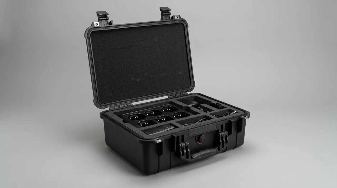
Verification after replacement must not be skipped. Three checks apply to a new liner: the lid latches naturally with everything loaded, the shake test produces no rattle, and for critical payloads one drop sequence confirms performance. Skipping them turns a liner change into a fresh failure risk.
Selection Checklist and Acceptance Points
The preceding sections reduce to a checklist, applied top to bottom.
First, fix the change frequency: above three changes a year choose pick-and-pluck or layered pads; at one change a year or fewer choose solid contouring; a main item with many accessories calls for a hybrid. Second, fix payload geometry: regular square items can use dividers to save cost, irregular items with protrusions must be contoured. Third, fix cushioning parameters: compute static stress from mass and fragility and read material, density and thickness off the cushion curve. Fourth, fix the case: choose a size from liner outline plus 20 to 30 mm allowance, confirming stacking datum and interior radius. Fifth, fix the internal environment: decide on desiccant, valve and breather grooves from the service environment.
| Decision item | Input | Output | Common error |
|---|---|---|---|
| --- | --- | --- | --- |
| Change frequency | Changes per year | Structure family | Solid contouring despite frequent change |
| Payload geometry | Measured shape, protrusions | Dividers or contouring | Dividers around irregular items |
| Cushioning parameters | Mass, fragility | Material, density, thickness | Guessing instead of calculating |
| Case size | Liner outline plus allowance | Case model | Sizing from brochure dimensions |
| Internal environment | Service temperature and humidity | Desiccant, valve | No desiccant in a sealed case |
| Spares | Cases in service | Stock quantity | No lid pads held |
Acceptance falls into four classes. Dimensions: liner to interior clearance 0 to 1 mm, critical cavity dimensions within drawing tolerance, total thickness within ±1.5 mm. Properties: hardness within ±5 points of nominal, density within ±8%, insertion force between 20 and 60 N. Function: the lid latches naturally when loaded, no rattle on shake, no abnormal latch load. Documentation: assembly drawing, material statement, maintenance guidance and change log complete.
For volume purchases, agree first-article approval and retained samples: build one approval liner, seal it as the comparison standard, and audit later batches against it under an AQL plan. This can run together with shell acceptance so liner and shell are assessed as one system rather than approved separately and assembled afterwards.
Frequently Asked Questions FAQ
Q: Should I choose pick-and-pluck foam or a custom contoured liner, and is pick-and-pluck only a temporary solution?
A: The deciding factor is not which performs better but how often the layout changes. Above three changes a year, pick-and-pluck or layered pads cost far less across the life of the case, because a contoured liner needs fresh profiling and often a new die every time, and change cost can be several times the liner price. Pick-and-pluck is also not merely temporary: secondary processing raises its protection considerably, for example consolidating torn walls with foam-grade adhesive to stop crumbling, leaving the bottom layer intact as a cushion pad, and adding a three to five millimetre low-density facing between payload and cavity to fill the steps. Together these bring it close to layered-pad performance. The structural limits remain: a stepped cavity cannot follow curved surfaces, and once the base is torn thin, bottom stroke drops sharply and the payload can bottom out, so it is still not recommended for payloads with fragility below 30 g. Keep a photograph of the finished layout so the same pattern can be reproduced when the block is eventually replaced.
Q: How much clearance should a case have, and how much preload is correct?
A: There are two kinds of clearance, controlled differently. Fit clearance between payload and cavity comes from interference: solid contoured liners take 0.5 to 1.5 millimetres per side, while pick-and-pluck needs 2 to 4 millimetres because the stepped cavity contacts poorly. Too little lets the payload shift and abrade; too much makes removal hard and accelerates foam fatigue. Free play in the closing direction is removed by preload, the percentage by which the lid pad compresses when the lid shuts, normally held between 20 and 30 percent, which stops the payload jumping and landing again inside the case. Verification must be done with everything loaded, checking four things: whether the lid latches without anyone pressing, whether latches show abnormal load, whether side walls bulge, and whether the lid-to-base joint opens when the case is lifted by the handle. The shake test remains the best field rule, since any rattle means unconstrained free play that needs a shim or a cavity correction.
Q: Does a foam liner make a sealed case more humid, and is a desiccant necessary?
A: Yes, and thicker liners make it worse. Three sources feed internal moisture: water carried in on the payload surface, moisture adsorbed in the foam, and vapour in the air sealed inside. Where day and night temperatures differ widely, relative humidity rises overnight and condensation forms on metal surfaces once the dew point is reached, which is a leading cause of corrosion and circuit faults in sealed cases. Foam permeability varies sharply: open-cell PU breathes but also absorbs and dries slowly, while closed-cell EVA, EPE and IXPE neither breathe nor absorb, so vapour migrates only slowly along cavity gaps and localised high humidity develops. The practical answer is a combination: dry the payload and liner thoroughly before packing, size the desiccant to interior clear volume and renew it on schedule, cut breather grooves into the liner away from load paths, and fit a membrane pressure valve where altitude or air freight is involved. Inspect the gasket whenever the liner is replaced, because a tired seal makes internal humidity track the outside and consumes desiccant faster.
Q: Can dividers and foam be combined, and when does a hybrid make the most sense?
A: Yes, and hybrids are the mainstream answer for complex loads. The decision rests on two questions: whether items are regular in shape, and whether the layout must change often. Regular items in a changing layout suit dividers; irregular items with protrusions in a fixed layout suit foam; everything between suits a hybrid. Three layouts recur: a contoured foam body with a divided accessory zone, so the main item is fixed and accessories are separated freely; a divider frame lined with three to five millimetres of foam, where dividers carry separation and load while the lining prevents slip and abrasion; and a foam base with upper dividers, where the base cushions and light accessories sit above. The specific risk is stiffness discontinuity, because the compliant foam zone and rigid divider zone concentrate shock along their boundary if it faces a drop corner, tearing foam or bending dividers. Also keep plug-in divider slot depth at least 1.5 times divider thickness, or the divider pulls out under side load.
Q: How long does a foam liner last, and are there quantifiable replacement criteria?
A: Four criteria are measurable. Thickness loss beyond ten percent, with visible compression at the cavity floor or lid pad and slow rebound. Insertion force falling below twenty newtons, so the payload moves when the case is gently shaken. Structural damage such as torn or crumbling cavity walls, broken divider clips, or a lift strap debonded at the root. Material ageing, where the surface turns tacky, powders or develops a clear odour, which means the polymer is degrading. Assessment intervals follow duty: daily high-frequency access every six months with replacement at one to two years; normal rotation annually with replacement at two to three years; long-term stacked storage every six months even when unused, because constant compression produces creep; extreme temperature and humidity every three months with replacement at one to two years. Hold spares at ten to fifteen percent of the case population and always include lid pads, which fail first. Every order must state the current drawing revision. Remanufacture is worth considering first, since a locally worn cavity can be cut out and replaced with matching material at a fraction of replacement cost.
Q: The case is too heavy and bulky to carry. How do I cut weight and volume without losing protection?
A: Four routes work. Improve cushioning efficiency by using the cushion curve to find the minimum thickness that satisfies fragility rather than adding thickness by habit, since moving from forty to thirty-two millimetres often drops the case one size and total weight by more than ten percent. Zone the material, because vulnerable features usually account for only twenty to thirty percent of surface area, so high-performance thick foam belongs there and thin low-density foam, or nothing, everywhere else. Redistribute mass by placing the heaviest item near the case centre and toward the handle, which does not change total weight but markedly improves handling and lowers the chance of tumbling. Consider material substitution, since EPP is typically thirty to forty percent lighter than EVA at equal cushioning, with low-density IXPE close behind, at higher cost and weaker contouring. One counter-intuitive option also helps: a larger shell with a thinner liner, because a bigger shell has a longer deformation stroke and absorbs more itself, which suits vehicle-based work but fails for single-person carrying.
Q: The lid will not close or the case bulges once loaded. What is wrong and how do I fix it?
A: This is the classic symptom of total liner thickness exceeding design, with four usual causes. Layered pads are added up from nominal thicknesses while ignoring adhesive films, each about 0.3 to 0.5 millimetres, so five layers add more than two millimetres. The lid pad is too thick or its compression has been miscalculated, since it should be sized for twenty to thirty percent compression. The liner outline was designed to nominal interior dimensions rather than the lower tolerance limit, and rotomoulded interiors can vary by three millimetres, so a small case either rejects it or forces it in. Relief for latches and handles was omitted, so the liner contacts the latch mechanism before seating. Work in order: measure actual total liner thickness and compare it with interior clear height to size the excess; identify which layer is out; reduce lid pad thickness or one separator pad rather than the main cushion layer, since that layer governs drop protection; then repeat the loaded closed-state checks, including the shake test, before releasing the case.
Q: One case has to carry different equipment. What is the most economical liner configuration?
A: Match the approach to how different the payloads are. For small differences, such as one family of instruments in several sizes, use layered pads: slice the interior horizontally and adapt by changing layer order, thickness and opening position, locating the layers with pins or posts, which are more reliable than an interference fit and longer lived than tape. For moderate differences, where shapes are similar but protrusions sit in different places, use swappable modules: cut the pad into standard modules, one per item, assembled through a common interface, keeping a continuous cushion base beneath the seams because cushioning is discontinuous there. For large differences, use interchangeable liner kits, one contoured liner per payload sharing a common shell, which costs the most but makes sense whenever the payload value far exceeds liner cost. Label each case with the configuration fitted and keep the revision on spares orders.
Conclusion and Related Reading
Selecting a foam insert case means solving shell stiffness, liner structure, clearance, volume and internal environment inside one constraint set, and JUNZHIJIA supports that from selection through custom liners and full case verification with OEM and ODM service.
Related Reading