


A flow battery, and especially an all-vanadium redox flow battery, is engineered almost nothing like a lithium-ion pack. Its energy is not sealed inside the electrode material of a cell; it is held in external electrolyte tanks, and at run time a circulation pump drives a vanadium-bearing sulphuric acid solution through the stack, where valence changes across an ion-exchange membrane convert chemical energy into electricity. The consequence is that the movable unit of a flow battery system is not one battery pack but a long chain of components whose sensitivities have almost nothing in common: the cell stack, the ion-exchange membrane, the bipolar plates, the felt electrodes, the tanks, the piping, the pumps and the valves. That chain leaves the assembly shop and passes through a test bench, a finished-goods store, long-haul road freight, a sea container and finally a site pad that may be only half sheltered. Any rough handling or long idle stretch along the way can surface later as a membrane puncture, a chipped plate edge, a weeping fitting or a loss of stack compression, and it will usually show up only after the system has been filled and cycled.
JUNZHIJIA takes a firm position on this category: a flow battery case must be designed around the longest idle segment and the roughest handling point in the chain, not around the comfortable conditions of the assembly shop. A stack is intolerant of shock, a membrane is intolerant of creasing, compression loss and dehydration, and an electrolyte loop is intolerant of corrosion and leakage. All three demands have to hold inside one case, and every opening and refitting has to be recordable and traceable. Treating the protection case as a passive container is the single most common reason flow battery components arrive with hidden performance loss rather than visible damage.
Table of Contents
- 1. Where Field Risk Comes From in Flow Battery Components
- 2. Handling Path for Stacks Through Build, Test and Site Replacement
- 3. Ion-Exchange Membranes and Bipolar Plates: The Two Most Fragile Core Components
- 4. The Electrolyte Loop: Tanks, Piping, Pumps and Valves in Transit
- 5. Electrolyte Corrosivity and Leak Containment
- 6. Shock and Vibration: The Sensitive Axes of a Stacked Cell Assembly
- 7. Sealing and Pressure Equalisation in an Acid-Vapour Environment
- 8. Liner and Compartment Design: Layering from Membrane Box to Full Stack
- 9. Stacking, Drop and Salt Spray Testing
- 10. Protecting Piping, Fittings and Fasteners as Sets
- 11. Marking, Traceability and Travelling Documents
- 12. Acceptance Criteria and Selection Checklist
- Frequently Asked Questions FAQ
- Conclusion and Related Reading
1. Where Field Risk Comes From in Flow Battery Components
The failure logic of a flow battery is quite unlike that of a lithium-ion pack. Lithium damage is mostly internal to the cell and irreversible, and it tends to reveal itself in a single moment as thermal runaway. Flow battery damage tends to be slow, distributed and cumulative: a crease in the membrane too faint to see, a small chip on the edge of a bipolar plate, a tie rod a few newton-metres short of its specified preload. None of these stops the system, but together they raise internal leakage current and cut coulombic efficiency month after month. By the time an operator notices, the source has long since left the site where the goods were dispatched.
The starting point for case design is therefore not impact resistance but the identification of which stresses change electrochemical performance in a hidden way.
| Risk category | Typical manifestation | Effect on components | Packaging countermeasure |
|---|---|---|---|
| --- | --- | --- | --- |
| Mechanical shock | Loading knocks, dropped cases, crane swing | Membrane creasing or puncture, chipped plate edge, broken end-plate ports | Fragility-based cushioning, corner wrap, travel stops |
| Sustained vibration | Long road legs, repeated transfers, container stacking | Relaxed stack compression, loosened tie rods and fittings, shifted liner | Compartment location, axial limit, torque witness marks |
| Electrolyte corrosion | Drip residue, acid vapour, vanadium ion ingress | Pitting of metal parts, detached labels, stress cracking | Acid-resistant liner, neutralising absorbent, drip tray |
| Leak contamination | Seeping fittings, tank residue spill | Environmental pollution, very high clean-up and claim cost | Secondary seal, absorbent pads, leak indication |
| Moisture and condensation | Day-night cycles, rain, humid sea freight | Membrane dehydration and shrinkage, damp felt, rusted metal | Desiccant, humidity indicator, pressure equalisation valve |
| Mixed or wrong parts | Plates, membranes and gaskets of one type but different batches stored together | Wrong build, scattered performance, broken traceability | Compartment marks, batch and serial binding |
The most underrated rows in that table are corrosion and leakage. Vanadium electrolyte is a high-concentration sulphuric acid system, and the pentavalent form is also a strong oxidiser; it attacks most ordinary carbon steels and aluminium alloys and will turn a paper label brittle and loose within days. If leakage occurs in transit, the loss is not limited to one case of components: it includes cleaning of the carrier vehicle, treatment of the ground along the route and possible compliance liability.
2. Handling Path for Stacks Through Build, Test and Site Replacement
One stack passes through four very different sets of conditions between assembly and site installation. What actually drives the packaging plan is where somebody will open the case and where somebody will lift it.
| Path node | Environment | Main risk | Packaging requirement |
|---|---|---|---|
| --- | --- | --- | --- |
| Stack assembly line-out | Controlled workshop, higher cleanliness | Lifting squeeze, side load on membrane | Dedicated tooling pallet, keep upright, no stacking on top |
| In-house test bench | Filled loop, wet, residual electrolyte | Drip residue, contaminated fittings | Drip tray, drainable structure, port caps |
| Finished-goods store | Ambient, multi-tier stacking | Long-term load, slow membrane dehydration | Tier limit, sealed against dehydration, periodic check |
| Long-haul road | Sustained vibration, wide temperature change | Relaxed compression, shifted liner | Cushioning liner, axial limit, torque marks |
| Sea container | High humidity, salt fog, long duration | Corrosion, condensation, moisture uptake | Barrier film, adequate desiccant, salt-fog protection |
| Site installation | Open or half-sheltered, crane lift, uneven ground | Shock, tilt, mis-seating | Lifting marks, tilt indicator, base guide |
| Return for repair | Carrying residue, possibly already leaking | Cross-contamination, spreading corrosion | Drain, neutralise, dedicated recovery cavity and seal |
| Spare parts dispatch | Small lots, direct to project site | Mixed with main units, crushed | Separate compartment, crush-resistant pack, own label |
The return-for-repair leg is a flow battery peculiarity. A lithium pack is usually swapped as a whole, while a flow stack often has to go back to the workshop for teardown and analysis, and a unit still carrying electrolyte may be regulated as dangerous goods. The case therefore has to be able to drain, neutralise and reseal. The applicable rules for that kind of shipment are set out in the discussion of hazardous goods transport rules for cases; the actual classification and any exemption must follow the regulations in force in the transport region concerned.
3. Ion-Exchange Membranes and Bipolar Plates: The Two Most Fragile Core Components
If the stack is the heart of a flow battery, the ion-exchange membrane is its valve leaflet. Perfluorosulphonic membranes are typically 50 to 200 micrometres thick, and what they fear is never weight as such but four specific actions: creasing, point loading, drying and contamination.
Creasing matters because a hard fold compresses the ion-conduction path along the fold line, raises local current density and makes that line the first place to age or perforate in service. A membrane roll wound at too small a diameter develops the same continuous curvature problem on its inner turns, so membranes should travel flat or on a large-diameter core, and no sharp corner may exist anywhere inside the case.
Point loading leaves an imprint that does not recover. Nothing heavy may sit on the top layer, and tools or fasteners must never be dropped onto a membrane for convenience.
Drying matters because a wet membrane shrinks as it loses water, and the resulting internal stress changes the tension state it will have when built into the stack. Membranes should be sealed with a humidity indicator card rather than simply laid in open-cell foam.
Contamination is the fourth route. Metal ions, oil, mould release agents and paper dust all degrade membranes, and iron or copper ions in particular occupy exchange sites and directly reduce voltage efficiency. The liner in contact with membranes must be clean, oil-free and non-shedding.
Bipolar plates are the other brittle family. Whether graphite, carbon-polymer composite or metal, a chipped edge or a scratched flow channel disturbs electrolyte distribution. The damage usually happens when a handful of plates is carried as a stack and the edges knock together under their own weight, so interleaving paper and edge wrapping are the cheapest countermeasures available.
| Component | Typical size and form | Sensitivity | Packaging points |
|---|---|---|---|
| --- | --- | --- | --- |
| Ion-exchange membrane | 50 to 200 micrometres thick, sheet or roll | Creasing, point imprint, dehydration, metal ion contamination | Travel flat or on large core, sealed against dehydration, clean oil-free liner |
| Bipolar plate | 1 to 5 millimetres thick, flat plate | Chipped edge, scratched channel, warping | Edge wrap, interleaving, flat location |
| Felt or cloth electrode | 2 to 6 millimetres thick | Loss of resilience under compression, oil and debris pickup | Crush-resistant pack, clean bag, no stacking |
| End and current collector plate | Several to tens of kilograms each | Flatness, threaded holes, lifting interface | Face down, port protection plugs, dedicated lifting points |
| Gasket | Thin sheet, plate-specific size | Deformation, oil pickup, stretching | Separate packing, no heavy load, keep away from oil |
| Stack fasteners | Tie rods, bolts, disc springs as a set | Mixed parts, corrosion, lost preload data | Kitted by stack, dry pack, torque record enclosed |
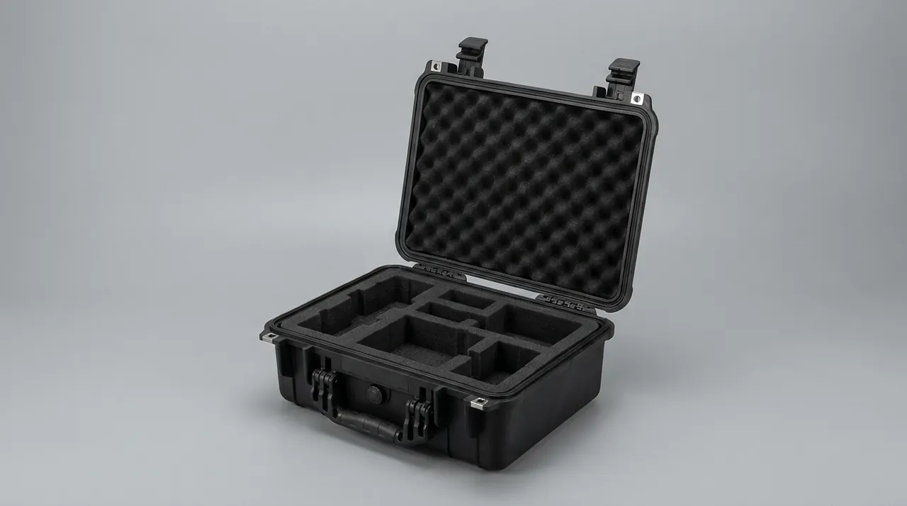
One point deserves emphasis: the condition in which a membrane travels is the condition it enters the stack with. A membrane that dried out in transit or picked up dust through static attraction will raise no alarm at build time, but the effect shows up over thousands of cycles. Membrane packaging is therefore not an accessory to logistics; it is part of stack assembly quality.
4. The Electrolyte Loop: Tanks, Piping, Pumps and Valves in Transit
The fuel tank of a flow battery is one or more external tanks ranging from a few hundred litres to tens of cubic metres. They are usually polypropylene, PVC, polyethylene or rubber-lined steel: large, top-heavy and full of fittings. Their protection priority is the opposite of the stack's. A stack fears shock; a tank fears stacking load and damaged interfaces.
| Component | Typical material | Failure mode | Trigger | Protection |
|---|---|---|---|---|
| --- | --- | --- | --- | --- |
| Electrolyte tank | PP, PE, PVC, lined steel | Shell distortion, damaged flange face, cracked port | Over-stacked, sling squeeze, forklift impact | Tier limit, dedicated slings, flange covers |
| Centrifugal circulation pump | PP or PVDF wetted parts, metal bearings | Bearing shock damage, distorted impeller, dry-run seal damage | Drop, long storage at an angle | Upright transport, axial limit, shaft-end guard |
| Magnetic drive pump | Seal-less, PVDF wetted parts | Cracked containment shell, demagnetisation from heat | Shock, storage near heat source | Cushioning liner, keep from heat, attitude marks |
| Transfer piping | PVC, PP, PTFE-lined, PE | Permanent bend, deformed end, liner separation | Small-radius bend, stacking load, sunlight | Straight runs in box, end plugs, no stacking on pipe |
| Valves | Ball, butterfly, diaphragm | Broken handwheel, struck actuator, damaged seat | Cantilevered load, impact with hard items | Handwheel clearance, separate compartments, valve position fixed |
| Heat exchanger | Plate or plate-fin | Distorted plates, cracked nozzle | Crane swing, stacking crush | Lifting marks, nozzle covers, vertical fixing |
| Online instrumentation | Sensors, electrodes, flowmeters | Broken probe, pulled cable | Overhang, cable carrying load | Dedicated probe cavity, coiled and fixed cable |
Large tanks present one easily missed problem: an empty tank is harder to restrain than a full one. It is light, top-heavy and has a large windage area, so airflow and inertia push it around the trailer, while an unsupported shell has less resistance to external pressure than a liquid-filled one. Empty tanks should be carried in dedicated saddles or with a sling array that limits movement, not simply propped with two pieces of foam.
5. Electrolyte Corrosivity and Leak Containment
The order of decisions in this area is: drain and neutralise first, then talk about cushioning.
Before dispatch, the stack and piping should be drained as far as practical. If liquid must be carried, for example because the stack has undergone an activation treatment, the shipment should be classified under the applicable dangerous-goods rules with the matching packaging and documentation. Whether or not liquid is carried, the packaging should assume that a small amount of leakage will occur and be designed accordingly.
The first layer is an acid-resistant liner. Any liner that may contact electrolyte should be polypropylene, polyethylene or PTFE-laminated. Ordinary open-cell polyurethane foam should be avoided: it absorbs liquid, loses its cushioning capacity and can be slowly attacked by acid vapour into powder that then contaminates membranes and felt electrodes.
The second layer is a secondary seal. Placing all components that could weep inside an acid-resistant bag or inner shell confines any leakage so that it cannot reach the outer case or the carrier's equipment.
The third layer is absorbency and neutralisation. An acid-resistant absorbent pad goes into the drip tray, together with a small quantity of a carbonate-based neutraliser. The pad provides volume and the neutraliser lowers local acidity; together they remain effective under transport vibration.
The fourth layer is leak indication. A colour-change strip or indicator at the outside of the case or at the base of the drip tray lets anyone judge at a glance, during transit or on arrival, whether leakage has occurred without opening the case.
| Leak source | Appearance | Direct consequence | Packaging countermeasure |
|---|---|---|---|
| --- | --- | --- | --- |
| Threaded fitting seep | Damp ring and crystallisation around the port | Corroded nearby metal, stained liner | Secondary seal, absorbent pad, port caps |
| Flange seep | Liquid in the flange gap | Pitted bolts, damaged gasket | Flange covers, drip tray, neutraliser |
| Tank residue spill | Pooling at the tank base | Large-area contamination, compliance risk | Full drain, sealed ports, upright fixing |
| Pump mechanical seal seep | Pooling under the pump body | Rusted bearings, damaged electrical parts | Sump, absorbent pad, electrical isolation |
| Aged hose rupture | Seep after a bulged wall | Sudden leak with no warning | Pre-shipment inspection, no sharp bends, date marking |
| Condensed acid vapour | Corrosion on inner wall and metal faces | Long-term corrosion, label loss | Equalisation valve, barrier film, acid-resistant labels |
It should be said plainly that vanadium electrolyte carries real environmental and personal risk: it is corrosive and irritant to skin, eyes and the respiratory tract, and pentavalent vanadium compounds are toxic. Case design therefore has to protect the person opening it as well as the component inside. A drip tray that lifts out as one piece, absorbent pads that can be swapped as a sheet, and an opening sequence that works from the outside inwards all materially reduce site exposure.
6. Shock and Vibration: The Sensitive Axes of a Stacked Cell Assembly
A stack is built from many single cells stacked in one direction and held by end plates and tie rods under preload. That structure makes its sensitivity anisotropic: compression change along the stack axis and shear perpendicular to it have completely different failure mechanisms.
| Load direction | Failure mechanism | Consequence | Liner strategy |
|---|---|---|---|
| --- | --- | --- | --- |
| Axial, along the stack | Compression overload or unloading | Permanent deformation of membrane and gasket, or rising internal leakage and shunt current | Axial travel stops, low-stiffness preload support, no direct end-face loading |
| Lateral, in the plate plane | Relative displacement of plate and membrane | Misaligned channels, shifted gasket, local leakage | Side location, tight compartment fit, limited cell clearance |
| Vertical drop | Corner and ports take peak acceleration | Chipped end plate, broken nozzle, damaged lifting point | Corner wrap, bottom load layer, drop height limit |
| Torsion | Tie rods and fasteners in bending | Scattered preload, damaged threads | Full pallet support, no cantilever placement |
| Long-term resonance | Progressive loosening of location | Secondary shock after the liner has failed | Avoid 5 to 50 Hz excitation, check liner on arrival |
There is a counter-intuitive engineering result worth stating: manual handling shock is often more severe than vehicle vibration. A single drop from 0.8 metres produces a peak acceleration far higher than the accumulated effect of hours of road transport, while the main harm from vehicle vibration is the slow relaxation of stack compression and slight drift of the liner. A test plan should therefore cover both drop and random vibration rather than choosing one. The general approach to those tests and their pass criteria is described in the discussion of transport vibration testing.
One more practice deserves a mention: torque witness marks are the invisible insurance of stack transport. Painting a witness mark across each tie rod nut and key fitting lets an inspector see on arrival whether anything rotated during the journey. It is far faster than re-measuring every torque value and provides objective evidence for release or rejection.
7. Sealing and Pressure Equalisation in an Acid-Vapour Environment
The sealing difficulty of a flow battery case differs from that of ordinary electronics packaging. It does not merely keep water out; it has to keep acid vapour in, while still allowing pressure to equalise.
Protection rating. The sealing level of a case should be stated and verified under IEC 60529 or GB/T 4208. IP65 resists water jets and suits most road and warehouse scenarios; where brief immersion or long outdoor storage is expected, an IP66 or IP67 structure should be chosen and confirmed by the corresponding test. The rating digits describe resistance to water and solid objects only, not resistance to acid vapour, and this is the most common source of confusion in selection.
Shell material. Material choice is a trade between acid resistance, impact resistance, weathering and cost.
| Material | Acid resistance | Impact | Weathering | Relative cost | Typical use |
|---|---|---|---|---|---|
| --- | --- | --- | --- | --- | --- |
| Homopolymer PP | Excellent | Medium | Medium | Low | Shell, liner, drip tray |
| PP with 30 percent glass fibre | Excellent | Good | Medium | Medium | Load pallet, structural parts |
| PC | Medium | Excellent | Good | Medium-high | Inspection window, panel |
| PC/ABS blend | Medium | Good | Good | Medium | General-purpose shell |
| ABS | Poor | Good | Medium | Low | Not recommended in acid vapour |
| EPDM gasket | Excellent | Not applicable | Excellent | Low | Continuous seal ring |
| FKM gasket | Excellent | Not applicable | Good | High | Hot or concentrated acid |
| ePTFE membrane | Excellent | Not applicable | Excellent | Medium | Pressure equalisation valve |
Pressure equalisation valve. In an acid-vapour environment the hydrophobic breathable membrane has to meet two conditions at once: it must block liquid water and electrolyte while resisting degradation by acid vapour. A standard hydrophobic membrane may change pore size or become brittle after prolonged acid exposure, so a chemically more resistant ePTFE is the better choice, and the valve body should be positioned clear of the drip tray and any pooling zone. Selection must consider opening differential, flow rate and membrane area, because too small an area cannot balance pressure during a rapid change. Mounting and maintenance are covered in the guide to pressure equalisation valve selection, and the compression and material pairing of the seal ring is covered in the guidance on gasket and O-ring material selection. If those two parameters are mismatched, no rating on the nameplate will survive contact with the field.
Structural load. Heavy items such as tanks and heat exchangers transfer load through a base pallet into the shell, so the corners and stacking faces need reinforcement ribs, and the load path from handle and latch should run directly into the shell frame rather than into a thin wall.

8. Liner and Compartment Design: Layering from Membrane Box to Full Stack
A flow battery shipment is hard to solve with the idea of one box holding one system, because a single consignment contains five categories at once: fragile, heavy, wet, dirty and traceable. Layering and compartmentalising is the more workable answer.
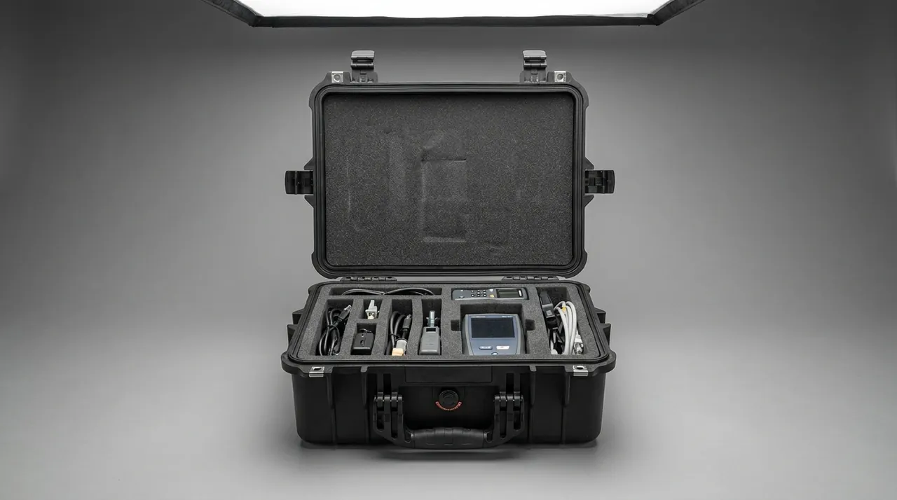
Layering runs from the outside in: a load-bearing layer, meaning the shell and pallet; a cushioning layer, meaning EPE or EVA; and a functional layer, meaning the acid-resistant barrier and the locating geometry. The cushioning layer absorbs energy, and the functional layer provides location, moisture resistance and liquid resistance. Neither replaces the other.
Compartmentalising typically produces a main cavity for the stack or tank, a spares cavity for membranes, plates, gaskets and fasteners, a tool cavity, a document pocket and a leak collection cavity. The greatest benefit is not tidiness but the severing of stress paths between components of different sensitivity: heavy parts no longer press on membranes, tools no longer strike plates, and leakage no longer reaches documents.
| Layer or cavity | Suggested material | Function | Caution |
|---|---|---|---|
| --- | --- | --- | --- |
| Cushioning layer | EPE, EVA | Absorb shock and vibration energy | Thickness must match fragility; too thin is useless, too thick wastes volume |
| Locating skeleton | Numerically cut or die-cut EVA | Limit movement, hold attitude | Avoid interference fit that hampers handling |
| Moisture barrier | IXPE, aluminium-laminate film | Reduce vapour transmission | Does not replace desiccant; pair with a humidity card |
| Acid-resistant functional layer | PP, PE, PTFE laminate | Resist electrolyte and vapour | Do not use water-absorbing open-cell foam |
| Leak collection cavity | Drip tray with absorbent pad and neutraliser | Contain and neutralise seepage | Tray lifts out whole; pad swappable as a sheet |
| Spares cavity | EVA compartments | Kit membranes, plates, gaskets, fasteners | Kit by stack, avoid cross-stack mixing |
| Document pocket | Separate moisture-proof bag | Paperwork and records | Isolate from components and residue |
For the general trade-offs between foam materials, the comparison of internal foam types for cases is a useful reference. Here it is enough to stress one flow-battery-specific principle: open-cell foam and an acidic medium environment are inherently incompatible. Ordinary open-cell polyurethane absorbs liquid and holds it, then slowly powders in acid vapour, losing cushioning and contaminating components. Liners should therefore favour high closed-cell content and chemical resistance, or laminate an acid-resistant barrier onto the foam.
9. Stacking, Drop and Salt Spray Testing
The purpose of testing is not to obtain a certificate but to reproduce the rough conditions of the field in the laboratory and expose the weak points of the design. A flow battery test plan should cover at least the following.
| Test | Purpose | Meaning for flow battery scenarios |
|---|---|---|
| --- | --- | --- |
| Controlled drop | Verify corner and liner energy absorption | Dropped by hand, crane impact on site |
| Random vibration | Verify location reliability under long vibration | Long road legs, intermodal transfer, container stacking |
| Stacking load | Verify loaded stiffness and sealing retention | Multi-tier storage, full sea container |
| Low pressure | Verify sealing and equalisation valve | High-altitude road leg and air freight |
| Temperature and humidity cycling | Verify condensation and material stability | Day-night cycles, humid sea freight |
| Salt spray | Verify corrosion resistance of metal parts and coatings | Coastal project sites and sea freight |
| Seal check | Verify leak rate and rating compliance | Every case making a sealing claim |
Test methods and pass criteria should come from the purchase specification and the agreed test plan. Shell testing can follow the GB/T 4857 series and the relevant ISTA procedures, and metal corrosion resistance can follow the guidance on reading a salt spray corrosion test using the method of GB/T 10125. Two caveats apply. First, the relationship between salt spray hours and service life involves real uncertainty, so a number of hours without rust should not be converted directly into a service-life claim. Second, a packaging test demonstrates only the packaging's capacity to withstand transport stress; it is not a statement about the stack's own performance, sealing class or any form of certification.
10. Protecting Piping, Fittings and Fasteners as Sets
What most often goes wrong on a flow battery site is not the big item but the small one: a squashed hose, a deformed threaded port, a set of bolts from the wrong stack.
| Item | Main risk | Protection | Arrival check |
|---|---|---|---|
| --- | --- | --- | --- |
| Pipe end and bevel | Deformed end, separated liner | End plug, fixed cap | Roundness and inner wall visual |
| Thread and flange | Damaged thread, scratched sealing face | Thread sleeve, flange face cover | Hand-thread check, face flatness |
| Hose | Sharp-radius crease, bulge, ageing | Large-radius coil, no stacking, shade | Appearance and crease marks |
| Butterfly and ball valves | Broken handwheel, drifted position | Handwheel clearance, position fixed | Open and close action, travel stop |
| Actuator | Housing impact, pulled cable | Separate compartment, coiled cable | Appearance and cable fixing |
| Fastener kit | Mixed parts, corrosion, flattened disc springs | Kitted by stack, dry pack | Quantity, specification, appearance |
| Sensor probe | Broken probe, calibration drift | Dedicated probe cavity, impact-free fixing | Appearance and enclosed calibration file |
Kitting is the highest-value measure in this section. Packing the tie rods, nuts, disc springs, gaskets and torque record for one stack into a single labelled set removes mixed parts, missing parts and broken traceability at the same time. Against the cost of one extra compartment in a case, the waiting time caused by a missing or wrong part on site is far more expensive.
11. Marking, Traceability and Travelling Documents
A distinctive feature of flow battery components is that the lives of items in one consignment differ enormously. The case should serve more than ten years, a membrane may be replaced after two, and gaskets are consumables. If the identification system does not distinguish these differences, traceability degrades quickly.
| Identification layer | Content | Durability requirement | Note |
|---|---|---|---|
| --- | --- | --- | --- |
| Component body | Model, batch, serial, production date | Same life as component | Follow the manufacturer's original marking |
| Compartment mark | Model and batch matching the body | Abrasion and wipe resistant | Print or laminate; avoid paper |
| Outside label | Case number, part number, quantity, stacking limit | Weather, handling and acid-vapour resistant | May carry a QR code |
| Handling and transit label | Dispatch date, carrier, tilt indicator status | Removable with no residue | Replaced each journey |
| Document pocket list | Packing list, material certificate, torque record, safety data sheet | Moisture-proof, isolated from components | Verified item by item |
The position of the document pocket should not be arbitrary. Place documents next to the drip tray and the first thing destroyed by a leak will be the very records that matter most, so the pocket should be independently moisture-proofed and kept away from anything carrying liquid. For how a single scan can read case number, batch and longest expiry, the approach described in asset QR-code tracking is especially effective across the multi-project, multi-site operation typical of flow batteries.
12. Acceptance Criteria and Selection Checklist
The conclusions of the preceding sections compress into a list that can be written straight into a purchase specification.
| Acceptance item | Criterion | Method |
|---|---|---|
| --- | --- | --- |
| Protection rating | Stated and verified under IEC 60529 or GB/T 4208 | Third-party or agreed sealing test |
| Shell material | Acid resistance, impact and weathering matched to intended life | Material certificate and specimen validation |
| Seal ring | Joint-free continuous ring, compression within design band | Dimension measurement and assembly check |
| Equalisation valve | Acid-vapour resistant, flow sufficient for pressure change rate | Selection documents and pressure balance test |
| Acid-resistant liner | Contact surface is PP, PE or PTFE laminate | Bill of materials and immersion test |
| Leak control | Secondary seal, absorbency and neutralisation present | Simulated leak test |
| Cushioning liner | Thickness matched to fragility, no shift after transit | Post-vibration and post-drop inspection |
| Compartment design | Main, spares, tool and document cavities present | Drawing review and sample check |
| Stacking capability | Loaded sealing retained at the marked number of tiers | Stacking load and loaded sealing test |
| Marking and traceability | Three redundant layers including batch and serial | Physical check and scan verification |
| Travelling documents | Packing list, material certificate, torque record, safety data sheet | Item-by-item count |
| Customisation and delivery | Liner tooling, OEM/ODM and batch consistency | First-article approval and batch sampling |
Two selection errors deserve a separate mention. The first is reading only the protection rating of the shell and ignoring the liquid resistance and compression performance of the liner. The second is treating salt spray hours as a service life. The first lets an IP67 case fail quickly in front of acid vapour and residue; the second leads to an over-commitment on the corrosion resistance of metal parts. Both are avoidable if the criteria are fixed at the design stage.
Frequently Asked Questions FAQ
Q: Why can flow battery components not simply reuse a lithium-ion packaging scheme?
A: Because the damage mechanisms and the sensitive objects are entirely different. A lithium pack normally ships as one unit, its protection priority is thermal runaway and short circuit, and the packaging stresses insulation, crush resistance and state-of-charge control. A flow battery's movable unit is instead a long chain of components with different sensitivities: a membrane that fears creasing, point loading, drying and contamination; bipolar plates that chip at the edge; tanks that fear stacking load and damaged ports; and a loop that fears corrosion and leakage. Reusing lithium packaging most often produces not a broken shell but four hidden damages, namely membrane dehydration and shrinkage, micro-cracks along plate edges, weeping fittings and relaxed stack compression. None of them shows at the moment of opening. They appear only after thousands of hours of cycling as falling coulombic efficiency and rising internal leakage, by which point the cause can no longer be traced. Choosing the wrong packaging scheme at the outset therefore costs far more than the price difference between the two cases, because the corrective action is not a new box but a rebuilt stack.
Q: What usually goes wrong with an ion-exchange membrane in transit, and how is it prevented?
A: Four things: creasing, point loading, drying and contamination, and none of them is easy to see on opening. Creasing comes from a roll wound at too small a diameter or from a sharp corner inside the case, and the fold line compresses the ion-conduction path so it becomes the first place to age in service. Point loading comes from stacking or from carelessly resting something heavy on the top layer and leaves an imprint that does not recover. Drying comes from inadequate sealing; a wet membrane shrinks as it loses water and changes the tension it will carry when built into the stack. Contamination comes from metal ions, oil and paper dust, and iron or copper ions occupy exchange sites and directly cut voltage efficiency. The countermeasures are to travel flat or on a large core, to ban end-face loading and stacking, to seal the pack with a humidity indicator card, and to use a clean, oil-free, non-shedding liner. Membrane packaging condition should be treated as a part of stack assembly quality, not as a logistics detail.
Q: Why is stack compression the key issue in transport protection?
A: Because a stack is built from many single cells stacked in one direction and held under preload by end plates and tie rods, and transport vibration and shock act directly on that load path. Compression overload permanently deforms the membrane and gasket, so after unloading there is internal leakage and rising shunt current. Insufficient compression lets plate and membrane shift relative to each other, producing local poor contact and uneven electrolyte distribution. Neither shows as an immediate shutdown; both slowly change the electrochemical performance of the stack. The packaging should therefore provide low-stiffness preload support and travel stops along the stack axis, avoid direct impact loading on the end face, and forbid cantilever placement and arbitrary turning. Painting a witness mark across tie rod nuts and key fittings adds a fast arrival check: any rotation during the journey is visible immediately, which is far quicker than re-measuring every torque value and gives objective evidence for release or rejection of the shipment.
Q: How should a stack carrying residual electrolyte be handled before dispatch?
A: In principle it should be drained as far as possible, and the packaging and documentation chosen to match the actual condition after draining. If liquid must be carried for a process reason such as activation treatment, the shipment should be classified under the dangerous goods regulations in force in the transport region, with the matching packaging class and paperwork, and a dedicated package able to drain, reseal and neutralise. Inside the case this means a drip tray, an acid-resistant absorbent pad and a carbonate-based neutraliser. Whether or not liquid is carried, the packaging should assume a small leak will occur: any liner that may touch electrolyte should be polypropylene, polyethylene or a PTFE laminate, the collection tray should lift out as one piece, and a leak indicator should be visible from outside. Vanadium electrolyte is corrosive and irritant to skin, eyes and airways, and pentavalent compounds are toxic, so the opening sequence should proceed from the outside inwards and operators should wear the specified protective equipment.
Q: How should shell material be chosen for an acid-vapour environment?
A: Put acid resistance ahead of impact resistance in the decision order. Homopolymer polypropylene gives the best combination of acid resistance and cost and suits the shell, liner and drip tray, although its stiffness and weathering resistance are only moderate. Adding roughly thirty percent glass fibre substantially raises load capacity and suits pallets and structural parts. Polycarbonate has the best impact and weathering performance but only medium acid resistance, so it is better used for an inspection window than for a body exposed to acid vapour over years. ABS is not recommended in an acid-vapour environment at all. For the seal ring, a continuous joint-free EPDM is low cost and resists both acid and weather; FKM can be considered for hot or concentrated acid duty, but at noticeably higher cost. For the equalisation valve, choose a chemically resistant ePTFE membrane and position the body clear of the drip tray, so that long-term acid exposure cannot alter pore size or embrittle the membrane.
Q: What special requirements does a pressure equalisation valve face in a flow battery case?
A: Beyond the usual hydrophobic breathable function, it must withstand long-term exposure to acid vapour, and that is the main difference from ordinary electronics packaging. A standard hydrophobic membrane may change pore size, become brittle or clog after prolonged acid exposure, and once equalisation fails the case builds negative pressure when the temperature drops and then draws humid outside air in the instant it is opened. In high-altitude road transport or air freight the opposite happens, and the seal is continuously pressed by internal pressure. Membrane material should therefore be a chemically more resistant ePTFE, and the valve body should be mounted clear of the drip tray and any pooling zone so the membrane is never submerged. Selection has to consider opening differential, flow rate and membrane area together, because too small an area cannot balance pressure during a fast change. Maintenance should include periodic inspection of the membrane face for dust, crystallised salt or grease. Keeping a spare membrane and a spare valve insert inside the case turns a field failure into a short planned stop instead of a return shipment.
Q: Why should ordinary open-cell polyurethane foam never be used as a liner?
A: Because open-cell polyurethane foam and an acidic medium environment are inherently incompatible. The open cell structure absorbs and retains liquid, and inside a case carrying acid vapour the foam can be slowly attacked and gradually turn to powder. It then loses cushioning capacity on the one hand, and on the other produces debris that contaminates ion-exchange membranes and felt electrodes. Wet foam also gains weight and changes its cushioning curve, so the thickness originally matched to the component's fragility no longer applies. A better approach is to choose materials with high closed-cell content and good chemical resistance, or to laminate an acid-resistant barrier of PP, PE or PTFE onto the outside of the foam, separating the cushioning function from the liquid-resistance function. Note that a barrier layer reduces vapour transmission but does not replace desiccant, so a humidity indicator card should still be used to monitor and record the internal condition. Open-cell foam also hides residue, which makes a genuine leak far harder to find during an arrival inspection.
Q: What acceptance criteria matter most for a flow battery protection case?
A: Group them into structure, liquid resistance, cushioning and traceability. The structure group covers whether the protection rating is stated and verified under IEC 60529 or GB/T 4208, whether the seal ring is a joint-free continuous ring with compression inside the design band, and whether sealing is retained at the marked stacking tiers. The liquid group covers whether liners touching electrolyte are PP, PE or PTFE laminate, whether secondary sealing and neutralising absorbency are present, and whether the equalisation membrane resists acid vapour. The cushioning group covers thickness matched to fragility, no shift after vibration and drop, and compartment layout that severs the stress path between heavy parts and membranes. The traceability group covers three redundant identification layers, batch and serial content, and verifiable travelling documents and torque records. A missing group can render the investment in the other three meaningless.
Conclusion and Related Reading
Flow battery transport protection fills the unsupervised interval between dispatch and first fill: limits and cushioning replace installation restraint, sealing and equalisation replace site ventilation, drip trays and neutraliser replace site drainage, and marking replaces the maintenance ledger.
Related Reading