

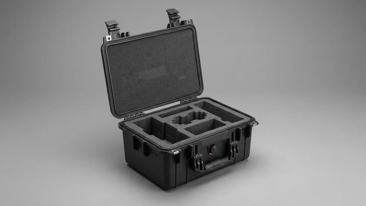
Aerial imaging work rarely happens indoors. Mountain survey routes, offshore wind decks, rooftop flight corridors, and improvised emergency launch points all mean the aircraft and everything mounted on it must survive repeated journeys through vibration, dust, moisture, temperature swings, and the occasional hard knock. The losses that hurt imaging teams most are seldom caused by the flight itself. They happen during the short, unglamorous transfer from vehicle to launch point: an airframe pinned under a tripod, a gimbal rocking until its damping balls fatigue, batteries baking on a rear seat, a controller with bent sticks from a lid pressing down.
JUNZHIJIA approaches drone case design from one position: treat the aircraft as a precision opto-electro-mechanical system, not as a plastic toy with propellers. The case must simultaneously solve impact isolation, attitude locking, particulate and moisture containment, battery heat and transport compliance, and the efficiency of "open and fly, pack and go." The value of a protective case is not measured by wall thickness. It is measured by whether the equipment is still flight-ready after every open-and-close cycle.
Table of Contents
- The Real Risk Profile of Drone Transport
- Payload Inventory and Cavity Planning
- Shell Material Selection: PP, PE, and Aluminum Extrusion
- Sealing and Ingress Protection: IP65 and IP67 in Practice
- Cushion Liner Design: EVA, EPE, and IXPE Combinations
- Locking the Gimbal and Lens Attitude
- Battery Transport: Thermal Control, Isolation, and Compliance
- Compartment Management for Controllers and Accessories
- Latches, Hinges, and Pressure Equalization Valves
- Stacking Load and Vehicle Vibration Testing
- Salt Fog, Humid Heat, and Long Outdoor Deployment
- The Customization Workflow: From 3D Scanning to Production
- Acceptance Checklist and Failure Mode Troubleshooting
- Frequently Asked Questions FAQ
- Conclusion and Related Reading
The Real Risk Profile of Drone Transport
Transport damage to aerial equipment falls into four categories with entirely different mechanisms, and each requires a different countermeasure.
Impact damage. A case drops off a tailgate or gets crushed by other gear. Peak accelerations easily exceed 30 g, while axial clearance in a gimbal motor is on the order of 0.05 mm. Energy that the liner does not absorb propagates as a stress wave into the sensor mount, lens bayonet, and ribbon cable.
Resonance and fretting wear. This is the most overlooked category. If vibration at a particular road speed approaches the natural frequency of the gimbal cantilever, a few dozen kilometers of driving relaxes fastener preload. Symptoms appear later as attitude warnings or a regular flicker in the video feed. When an ordinary box leaves equipment semi-free, fretting never stops.
Environmental attack. Coastal salt fog corrodes aluminum parts and connector contacts. Fine dust works into gimbal rails and motor gaps. Condensation at a post-rain launch site travels along cooling ducts into the airframe.
Thermal and regulatory risk. Battery temperature inside a closed case defines the safety margin, and air transport imposes explicit constraints on state of charge, packaging, and labeling.
| Risk type | Typical trigger | Damage observed | Countermeasure |
|---|---|---|---|
| --- | --- | --- | --- |
| Impact | Tailgate drop, stacking crush | Tilted gimbal, loose bayonet, cracked shell | Graded cushion liner plus hard stops |
| Resonance / fretting | Long highway or off-road haul | Backed-out fasteners, jitter, worn ribbon | High-damping EVA, full-contact locating |
| Environmental attack | Coastal, desert, rain, snow | Oxidized contacts, sticky rails, mold | IP65/IP67 sealing plus desiccant bay |
| Thermal and regulatory | Sun-exposed cabin, air freight | Swollen cells, refused shipment | Isolated cells, heat spreading |
| Handling error | One-hand opening, lid rebound | Broken blades, lid striking gear | Paired latches, limited hinges |
An effective design assigns every risk source an explicit engineering countermeasure and hard-wires those countermeasures into the packing procedure, so the operator never has to improvise.
Payload Inventory and Cavity Planning
Cavity planning is the first decision in drone case design and the one most often done badly. Many teams only discover after delivery that the folded airframe footprint differs substantially from published unfolded dimensions, or that controller antennas land exactly on top of the airframe.
Start with a payload matrix: list every item, annotate dimensions, weight, sensitive areas, and access frequency, then allocate positions by three rules. Frequently accessed items go toward the outside, heavy items toward the bottom, and sharp corners never share a cavity with optical surfaces.
| Item | Typical weight | Sensitive areas | Recommended position |
|---|---|---|---|
| --- | --- | --- | --- |
| Airframe, arms folded | 0.9–2.4 kg | Gimbal, motor shafts, downward sensors | Central cavity, full bottom contact |
| Spare propellers | 0.05–0.15 kg | Tips, hub bores | Side slots, stacked separately |
| Controller | 0.6–1.2 kg | Sticks, antennas, screen | Upper side cavity, sticks to wall |
| Flight batteries, four units | 0.5–0.7 kg each | Cells, connectors, shell clips | Individual cells, vertical or angled |
| Camera and gimbal payload | 0.2–1.5 kg | Front element, bayonet, ribbon | Shallow cavity, silicone cradle |
| Filter set | Under 0.3 kg | Coated surfaces | Tray with rigid backing |
| Tablet or field monitor | 0.5–1.0 kg | Screen | Upper layer, screen inward |
| Tool kit and cabling | 1–3 kg | Connectors | Separate lower cavity |
Then run a cavity dimension check. Slot depth must not equal equipment height: leave 2–4 mm of compression allowance so the EVA applies light preload once the lid closes. Too little preload and the item is not located; too much and long storage leaves permanent witness marks.
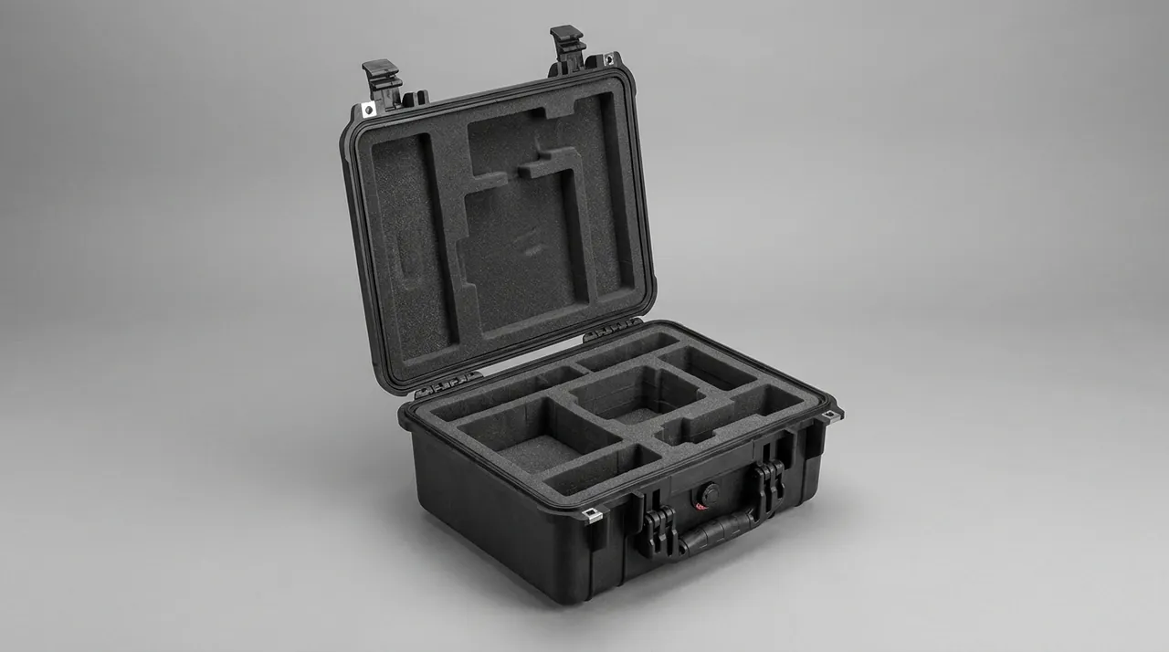
Planning must also consider the relationship between center of gravity and handle position. With the case loaded, the center of gravity should sit under the handle or slightly toward it, so a one-handed carry does not produce violent tilt. Batteries clustered in one corner make the case carry off-balance, which increases wrist fatigue and makes corner impacts more likely.
Shell Material Selection: PP, PE, and Aluminum Extrusion
Material sets the floor of what a case can do, and choosing the wrong route causes more trouble than choosing the wrong dimensions.
Injection-molded PP is formed in a single shot in a large mold. Wall thickness is uniform, dimensional accuracy is high, and surface detail is rich, so ribs, handle recesses, and latch seats can be molded as integral features. The advantages are low weight, production cost that falls steeply with volume, and appearance consistency. The limits are high tooling investment and part size constrained by clamping force.
Rotomolded PE is produced by rotational molding of powder, giving a seamless part with outstanding impact toughness and walls of 6–12 mm. For carrying a multirotor with arms deployed, drop resistance is clearly superior. The cost is weight, lower surface finish, and wider tolerance.
Aluminum extrusion combines extruded frames, aluminum or composite panels, and corner castings joined by rivets or bolts. Stiffness is high, geometry is rectilinear, and flat panels make sealing and lock layout straightforward. Thermal performance suits continuously heat-generating equipment. The drawbacks are the highest weight at a given protection level and the need for insulating gaskets between dissimilar metals.
| Shell route | Impact resistance | Weight | Tooling investment | Typical fit |
|---|---|---|---|---|
| --- | --- | --- | --- | --- |
| Injection PP | Medium | Light | High, large mold | Single-aircraft portable setups |
| Rotomolded PE | High | Heavy | Medium | Full aircraft, heavy payloads |
| Aluminum extrusion | Medium-high | Heaviest | Low, cut and assemble | Ground stations, rack cabinets |
JUNZHIJIA selects material by total system weight and transport mode, never by price alone. Under 5 kg fully equipped, with vehicle and hand carry, injection PP offers the best balance. Above roughly 10 kg, or where a multi-day road haul involves rough handling, rotomolded PE becomes decisive. See rotomolded protective case structure and rotomolding versus injection molding.
Sealing and Ingress Protection: IP65 and IP67 in Practice
Ingress protection ratings describe resistance to solids and water under IEC 60529 or the equivalent GB/T 4208. For aerial equipment the mechanisms differ: IP65 protects against water jets directed at the enclosure, while IP67 protects against temporary immersion at a defined depth and duration.
| Rating | Dust | Water form | Test conditions | Fit for aerial work |
|---|---|---|---|---|
| --- | --- | --- | --- | --- |
| IP54 | Limited | Splashing | Splash from all directions | Indoor transfer, dry regions |
| IP65 | Dust-tight | Water jets | 6.3 mm nozzle, about 12.5 L/min | Outdoor use, brief rain |
| IP66 | Dust-tight | Powerful jets | 12.5 mm nozzle, about 100 L/min | Decks, heavy rainfall |
| IP67 | Dust-tight | Immersion | 1 m depth, 30 minutes | Water crossings, emergency scenes |
The practical question is whether the case ends a working day in standing water. Mountain survey vehicles park beside muddy runoff; offshore wind decks hold continuous water; emergency work often requires opening a case in rain to swap a battery. Under those conditions IP67 is the more defensible choice.
Understand that an IP rating is a property of the complete case system, not of the gasket alone. A case rated IP67 whose latches are not fully engaged, whose gasket carries a grain of sand, or whose vent is left open performs far below IP54 immediately. JUNZHIJIA therefore fits a pressure equalization valve rather than a permanently open vent, resolving lid suction while preserving sealing integrity; see how a pressure equalization valve works. Silicone or EPDM at 40–60 Shore A with 20%–30% compression is the common gasket specification.
Cushion Liner Design: EVA, EPE, and IXPE Combinations
The liner is the part that actually does the work. The shell provides form and containment; the liner decides whether impact is absorbed and whether equipment is truly located.
EVA recovers well, cuts cleanly, and resists water absorption, with density typically 38–80 kg/m³. Higher density means greater compressive strength but a shorter cushioning stroke. For precision gimbals, 45–60 kg/m³ offers support while still deforming controllably.
EPE is softer, lighter, and highly resilient, suiting surface layers and repeatedly compressed top cushions. Its weakness is low tear strength, so deep pockets cut into EPE tend to tear in service.
IXPE has finer cells and a flatter surface, suiting thin conformal wraps over curved parts at 1–3 mm, suppressing fretting without witness marks.
| Material | Density range | Primary role | Thickness | Cautions |
|---|---|---|---|---|
| --- | --- | --- | --- | --- |
| EVA, medium | 45–60 kg/m³ | Load bearing, locating pockets | 20–60 mm | Seal cut faces to limit crumbs |
| EVA, high | 65–80 kg/m³ | Base bearing, sharp corners | 15–30 mm | Too hard shortens the stroke |
| EPE | 20–30 kg/m³ | Top cushion, void filling | 10–40 mm | Never alone for deep pockets |
| IXPE | 30–50 kg/m³ | Conformal wrap, anti-fretting | 1–3 mm | Needs reliable adhesive |
| Rigid PE foam | 30–45 kg/m³ | Large-cavity structural fill | 30–100 mm | Strong support, poor cushioning |
Multi-layer construction is standard. A 15–20 mm high-density base bears load, a 40–60 mm medium-density layer carries the cut pockets, and a 10–20 mm EPE layer bonded to the lid provides soft preload. This hard-base, medium-core, soft-cap architecture attenuates peak acceleration into a tolerable range. Quantitative comparisons appear in protective case foam material comparison.
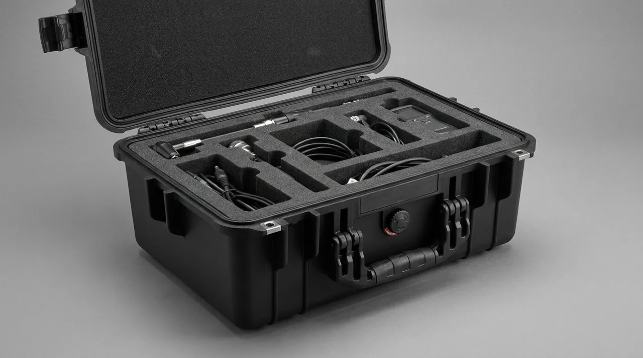
A useful rule is that every degree of freedom should be constrained by at least two faces. The base supports from below, pocket walls locate laterally, and the soft cap preloads from above. Slender items such as arms should never bridge an open cavity.
Locking the Gimbal and Lens Attitude
The gimbal is among the most fragile and most expensive parts of an aircraft, and its damage usually accumulates rather than arriving in one blow. With power off, gimbal motors are free. Damping balls deform back and forth throughout a drive, producing fatigue, ribbon cable wear, and limit structure damage.
Three measures are effective. First, use the gimbal guard or locking clip. Most platforms offer an official retainer whose purpose is to mechanically lock the gimbal in a defined attitude. It must be installed before packing; no liner conformality stops a free gimbal from swinging. Second, use a dedicated shallow cavity rather than a through cavity, separating airframe and camera with an 8–12 mm EVA divider so that airframe movement cannot drag the camera. Third, fix and reproduce the lens orientation, orienting the lens upward or toward a fixed wall with a shallow barrel cradle and a thin IXPE lining, seating with slight interference so no rotational freedom remains.
| Failure mode | Trigger | Early symptom | Design countermeasure |
|---|---|---|---|
| --- | --- | --- | --- |
| Damping ball fatigue | Fretting without locking | Low-frequency jitter | Retainer plus dedicated cavity |
| Ribbon cable wear | Free gimbal swing | Intermittent dropouts | Attitude constraint, limit wall |
| Loose lens bayonet | Axial impact | Edge softness | Axial stop, base cradle |
| Lens fungal growth | Humid storage | Spider-web haze | Desiccant bay, sealed shell |
| Filter coating scratches | Filters stored loose | Veiling flare | Filter tray, rigid backing |
For teams carrying multiple lenses or third-party payloads such as thermal modules, swappable liner trays are worth the investment: each payload gets its own tray, exchanged before a mission, guaranteeing conformal locating without tooling separate cases.
Battery Transport: Thermal Control, Isolation, and Compliance
Batteries deserve the most serious treatment of any payload: they combine stored energy, thermal runaway risk, and regulatory constraints in one component.
Placement should satisfy three conditions: individual cells, no metal contact, and distance from heat sources. Individual cells prevent compression between packs and against hard objects, and avoid stacking heat output. No metal contact prevents connectors or tabs from being bridged by tools or loose screws. Distance from heat sources keeps batteries out of lid liners that may see direct sun.
| Battery transport point | Engineering implementation | Common mistake |
|---|---|---|
| --- | --- | --- |
| Short-circuit prevention | Compartment pads, uniform terminal orientation | Storing batteries with tools |
| Compression prevention | One pack per cell, 2–3 mm lateral preload | Several packs crammed together |
| Thermal control | Avoid sun-exposed lid surfaces | Batteries in the lid liner |
| Moisture control | Desiccant bay plus gasket | Long-term storage with lid open |
| Traceability | In-case label and charge-state card | No record of battery state |
Air transport of lithium-ion batteries commonly requires approximately 30% state of charge, protected terminals, and packaging that prevents movement and damage in transit. Requirements differ between carriers and routes, so the carrier's current rules always govern.
One frequently missed detail is the interaction between pressure equalization and the battery. A case sealed while hot develops internal negative pressure as it cools, sucking the lid down at opening. A case closed in the cold and brought into a warm room develops positive pressure that can lift the lid and upset equipment stored above. Higher-specification cases therefore use a closable equalization valve.
Compartment Management for Controllers and Accessories
Workflow efficiency depends heavily on the time between opening the case and taking off. When the controller, tablet, video link, and cabling share one large cavity, every setup involves searching and untangling. Repeated cable tangling and connector bending are themselves damage mechanisms.
Controller cavities must orient the sticks toward a case wall or downward, never upward against the lid liner, because lid pressure directly deforms the potentiometers. Fixed antennas need a dedicated slot; detachable antennas are better served by a clamping slot alongside.
Tablet and monitor cavities must keep the screen away from every hard surface. The usual approach is screens inward and backs outward, with a thin IXPE layer on the screen side and small EVA corner blocks supporting the device in suspension. Where dimensions allow, an embedded slide-in format further reduces handling friction.
Cables and connectors deserve individual cells or a spool, grouped by function, with connectors clamped rather than loose.
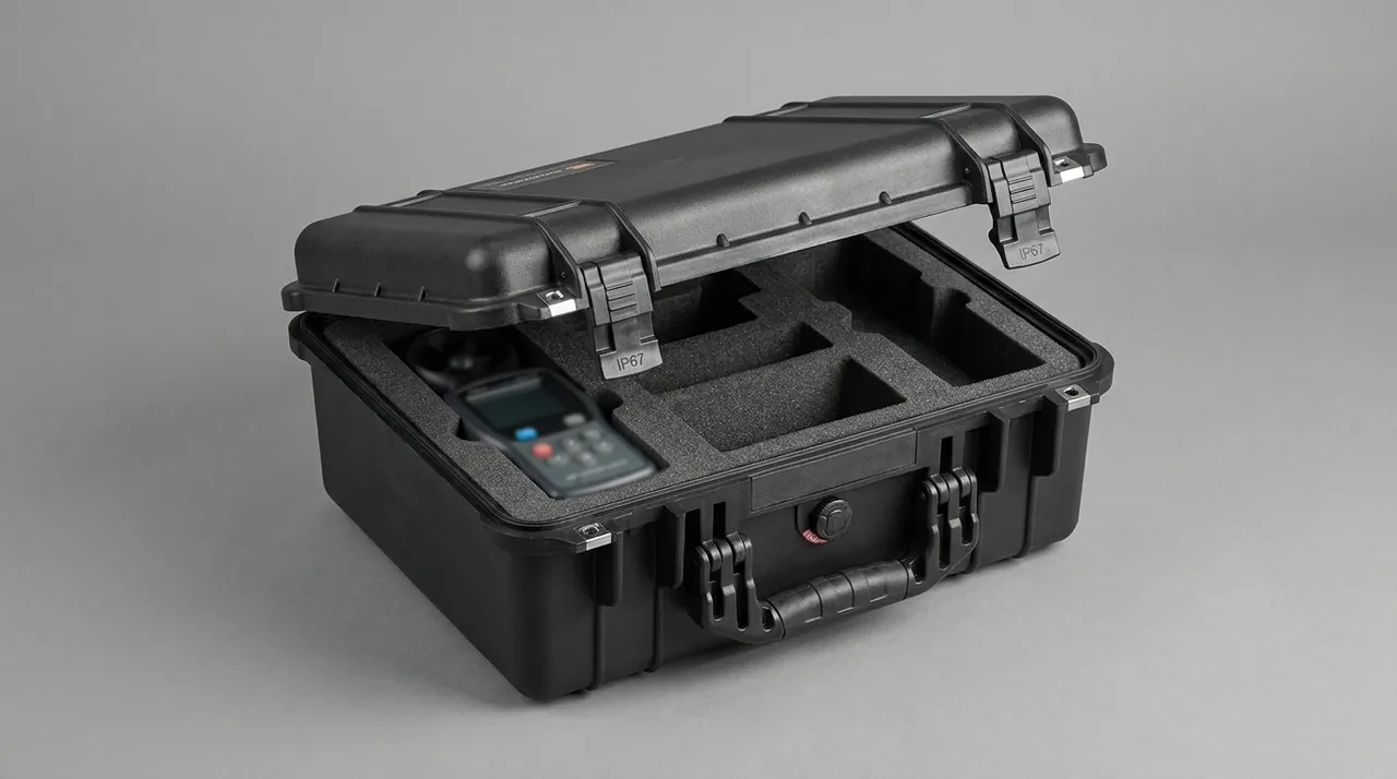
Spare propellers should be stacked flat with thin EVA sheets between adjacent blades, and tips must never bear against a cavity wall. Propellers are consumables: any delamination or crack requires replacement, so reserve a dedicated cell for damaged blades to keep them from mixing with serviceable stock. More ideas appear in drone accessory case compartment design.
Latches, Hinges, and Pressure Equalization Valves
These are the small but decisive components of a case, and any one failing drops protection to zero.
Latches need symmetrical placement and a reliable closing feel. Above roughly 500 mm of case length, one latch per side cannot distribute compression evenly around the sealing perimeter, so two or more pairs are normal. Anti-accidental-opening features prevent vibration or scraping from popping them. The most direct check that a latch is engaged is full contact between latch and catch plus a continuous compression witness on the sealing face.
Hinges define lid travel and opening limit. For heavy equipment, hinges should support the lid's weight and hold at any angle, or provide a positive stop at full opening to prevent the lid slamming back under wind load. The junction between metal hinges and molded shell is a classic stress concentration point.
Pressure equalization valves solve pressure differential from temperature change. Design considerations include diaphragm cracking pressure, membrane airflow capacity, and sealing reliability in the closed state.
| Component | Key metrics | Consequence of failure | Verification |
|---|---|---|---|
| --- | --- | --- | --- |
| Latch | Holding force, anti-pop, fatigue | Pops open in transit | Inspect after 500 cycles |
| Hinge | Load, opening stop, corrosion | Lid slams back, fracture | Static hang test, loaded lid |
| Gasket | Shore hardness, compression, aging | Water ingress, condensation | Witness check, spray test |
| Valve | Cracking pressure, airflow | Suction or pop on opening | Opening force after cycling |
| Handle | Load, grip, return | Fracture, pinched fingers | Hang test at twice rated load |
Gasket maintenance matters equally: after every outdoor job, wipe the groove and gasket with clean water to remove sand and salt, and check for flattening or hardening. Gaskets are consumables. See seal ring replacement and care and judging seal ring aging.
Stacking Load and Vehicle Vibration Testing
Structural strength is tested not only in a drop but continuously under stacking and vehicle transport.
Stacking load is governed by the compressive stiffness of side walls and lid. If stiffness is insufficient, the case bulges inward and the sealing face deforms over time, so design practice raises it through ribs, double-wall construction, and thickened corners. Establishing a stacking height combines fully loaded weight, storage temperature, since heat reduces the elastic modulus of plastics, and permitted storage duration.
| Test | Reference standard | Key conditions | Acceptance points |
|---|---|---|---|
| --- | --- | --- | --- |
| Drop | ISTA series, GB/T 4857.5 | Corner, edge, face drops | No rupture, no displacement |
| Vibration | ASTM D4169, GB/T 4857.7 | Random and fixed frequency | No loosening, no liner powder |
| Stacking | GB/T 4857.3 | Constant load, defined duration | No bulging, no collapse |
| Spray and immersion | IEC 60529 | Conditions for the declared rating | No internal water traces |
| Salt fog | GB/T 10125 | Neutral salt spray, defined duration | No red rust as agreed |
Vehicle transport adds one issue: how the case is restrained inside the vehicle. Even a case that passes vibration testing accelerates forward under hard braking if it is not tied down, striking the cab bulkhead or other cargo. Reserve tie-down points or anti-slip feet at the base. Related: sea freight and long-haul transport and benefits of stackable toolbox design.
Salt Fog, Humid Heat, and Long Outdoor Deployment
Salt fog mainly attacks metal components: latch rivets, hinges, valve parts, and the profiles and corner castings of aluminum cases. It destroys the passive film on metal surfaces and initiates pitting and galvanic corrosion. GB/T 10125 defines the test method, but there is no simple conversion between test duration and service life. Real life depends on salt concentration, wet-dry cycling, temperature, and maintenance, so hour-to-year conversions are unsound. Select stainless steel or properly treated components and rinse the exterior after every coastal job.
Humid heat and condensation present the more realistic threat. By day the case heats in the sun, internal air expands and vents; at night the temperature falls and internal negative pressure forms. If sealing is imperfect, external moisture enters with returning air and condenses inside, causing fungal growth in lens assemblies, damp circuit boards, and oxidized connectors.
| Environment | Primary threat | Protection measure | Maintenance action |
|---|---|---|---|
| --- | --- | --- | --- |
| Coastal salt fog | Metal corrosion | Resistant metal, sealed shell | Rinse exterior after each job |
| Humid tropics | Condensation, mold | Desiccant bay, sealing | Replace desiccant on schedule |
| Desert dust | Particles in rails | Dust-tight construction | Wipe the case before opening |
| Cold highlands | Brittle material, hard gaskets | Low-temperature rated materials | Avoid violent opening when cold |
| Rainy season | Water ingress | IP67 sealing, drain provision | Inspect gasket witness marks |
A desiccant bay is a low-cost, high-return feature. Provide a dedicated compartment for replaceable silica gel and record the replacement date. Desiccant only absorbs residual internal moisture; it cannot compensate for continuous ingress caused by a sealing failure, so it supplements sealing rather than replacing it.
The Customization Workflow: From 3D Scanning to Production
Airframes iterate quickly and no case maker can pre-tool a liner for every model, so most cases built for imaging teams are custom liner projects.
Requirements confirmation defines the payload list, platform model, whether a spare airframe or third-party payload must share the case, transport mode, protection rating, and whether wheels or a telescopic handle are needed.
Data acquisition uses either a supplied 3D model with key protrusion locations, or a 3D scan of the physical equipment. For complex curved components such as gimbals and lenses, scanning delivers noticeably better accuracy.
Cavity design works from the model while verifying compression allowance after lid closure, grab points, and handling clearance. This stage normally produces a layout drawing for customer confirmation. Prototype fitting produces the first EVA liner by CNC cutting, loads the actual equipment, and checks interference, grab point ergonomics, and smooth lid closure. Verification testing runs drop, vibration, or spray checks to confirm negligible equipment displacement after impact. Production cuts or molds liners in batch to the confirmed drawing with critical dimension re-inspection on every unit.
| Stage | Deliverable | Common rework point |
|---|---|---|
| --- | --- | --- |
| Requirements | Requirement sheet | Omitted third-party payload |
| Data acquisition | Model or dimension drawing | Folded arm dimensions missing |
| Cavity design | Layout drawing | Grab point pinches fingers |
| Prototype fitting | First article liner | Insufficient clearance |
| Verification | Test record | No physical road trial |
| Production | Shipping report | Batch color variation |
JUNZHIJIA supports the transition from single-piece prototyping to volume supply and can provide tooling, OEM and ODM services, and case documentation including packing lists, liner layout drawings, care instructions, and desiccant record cards. Process detail is covered in EVA foam insert customization and design points for pre-cut foam.
Acceptance Checklist and Failure Mode Troubleshooting
When a new case arrives, acceptance should not stop at appearance. Run a complete packing rehearsal against the checklist below.
| No. | Check item | Acceptance criterion | Action if failed |
|---|---|---|---|
| --- | --- | --- | --- |
| 1 | Shell appearance | No cracks, distortion, or sharp edges | Reject or replace |
| 2 | Gasket | Seated, untwisted, continuous witness | Reseat |
| 3 | Latches | Symmetrical engagement, no binding | Adjust or replace |
| 4 | Equalization valve | Opens and closes freely, no leak | Inspect diaphragm seal |
| 5 | Liner pockets | Conformal, 2–4 mm preload | Rework liner |
| 6 | Packing rehearsal | Full list fits, lid closes smoothly | Re-layout |
| 7 | Access efficiency | Packing within 3 minutes | Optimize grab points |
| 8 | Loaded carry | Stable center of gravity | Rebalance distribution |
| 9 | Spray test | No internal water or damp liner | Inspect sealing face |
| 10 | Documentation | List and care card present | Supply missing documents |
The recommended troubleshooting order is action first, sealing second, structure last. Many cases reported as leaking turn out to have latches that were never fully engaged, or a grain of sand on the gasket. Many cases reported as having loose equipment turn out to have pockets cut 1–2 mm oversized or foam of insufficient density. Fixing the diagnostic order avoids pointless structural reinforcement.
A further practical step is to keep a case log. Number each case and record the commissioning date, transport routes, maintenance actions, and gasket replacement dates. When something goes wrong, the log quickly establishes whether the problem belongs to a specific route or a specific case.
Frequently Asked Questions FAQ
Q: Is a thicker drone case always safer? Would a 10 mm wall be better than 6 mm?
A: Not necessarily, and the reasoning matters more than the answer. Wall thickness primarily provides structural stiffness and resistance to cracking during a drop, but the damage an impact delivers to equipment depends on the cushioning stroke of the liner and how completely the equipment is constrained inside. A 10 mm shell with only 15 mm of liner and oversized pockets lets equipment move freely, which produces greater damage risk than a 6 mm shell with 45–60 kg/m³ medium-density EVA, 2–4 mm preload, and full-contact locating. The correct engineering sequence is to establish the allowable acceleration at the sensitive area, derive the required cushioning stroke from it, and only then specify wall thickness and rib geometry. Heavier walls also increase one-handed carry fatigue and can make the case harder to secure inside a vehicle. In short, define the cushioning structure first, then the shell material and wall thickness. A practical point is that props and gimbal arms should be removed or folded into their own relief so they are not left as unsupported cantilevers that take the first impact of a drop and can crack the airframe joints.
Q: For aerial work, does the difference between IP65 and IP67 matter enough to justify the extra cost?
A: It depends entirely on where the case ends its working day. IP65 addresses water jets, such as carrying the case from a vehicle to shelter in rain. IP67 addresses temporary immersion, such as a case left in standing water on a vessel deck, in a puddle beside a mountain road, or on a roof during a brief downpour. Teams working vessel-borne operations, water crossings, or emergency response will find IP67 genuinely necessary, because those scenarios put the case in contact with pooled water rather than spray. If work is mostly indoor transfer and dry-region shoots, IP65 is sufficient and the saved budget is better spent on a more precisely cut liner. A practical test is to recall the worst single transfer of the past year and ask whether the case touched standing water. Remember that IP67 assumes fully engaged latches, a clean gasket, and a closed equalization valve, so if any of those conditions fails, real protection drops well below the nominal rating.
Q: Do lithium batteries inside a protective case create thermal runaway risk that requires special design?
A: Yes, special design is warranted, but the key is not simply separating batteries from other gear. Risk arises from three stacked factors: external heat input, internal short circuits, and cell-to-cell thermal propagation. Three engineering measures address them. First, give each battery its own compartment, one pack per cell, with 2–3 mm lateral preload to prevent compression and to keep terminals away from conductive objects such as tools and loose screws. Second, keep batteries out of lid liners and any position exposed to direct sunlight, which limits external heat input during vehicle transport. Third, leave a path for heat to spread rather than packing all packs into one closed pocket. Air transport also imposes requirements on state of charge, terminal protection, and packaging for spare batteries, and these vary by carrier and route, so the carrier's current rules must always be followed. Periodic inspection for swelling or shell dents completes the picture. Also keep batteries away from any heat source in the vehicle and avoid leaving a closed case in direct summer sun for extended periods, because internal temperatures can rise well above ambient and accelerate cell aging. Recording charge state and inspection dates on the in-case card makes it easier to retire packs before they become a liability.
Q: After a long transport, why does my gimbal show image jitter even though the case looks completely undamaged?
A: This pattern typically indicates resonance and fretting wear rather than impact damage. An intact case means no impact large enough to crack it occurred, but if the equipment retains a small degree of freedom, sustained vehicle vibration repeatedly deforms the gimbal damping balls, gradually relaxes fastener preload, and flexes ribbon cables near their anchor points. After several hundred kilometers the dynamic behavior of the damping balls changes and low-frequency jitter appears in the footage. Three corrective directions apply. First, confirm the gimbal retainer was installed before packing, which is the most frequently skipped step in the whole workflow. Second, check whether the liner pockets are oversized and shim them with thin IXPE where necessary. Third, check whether the gimbal cavity connects directly to the airframe cavity and add an EVA divider if it does. A physical road trial with an accelerometer during first-article customization is strongly recommended. For a case that travels by air, the battery cells are best carried separately and at storage charge, because a sealed case holds heat and a fully charged pack in an insulated box can be left warmer than the surrounding cargo.
Q: Is EVA or EPE the better liner material, and why not use pure EPE to reduce cost?
A: Pure EPE typically runs 20–30 kg/m³. It is soft, resilient, and inexpensive, but its tear strength is low, so deep cut pockets tend to tear and propagate along the cut once in service. After a few packing cycles the cavity deforms and the equipment loses its locating reference, which shows up later as a gimbal that will not hold attitude or a lens that will not seat properly. EVA can be formulated at 45–80 kg/m³ with markedly better compressive and tear performance, stable cut faces, and pocket geometry that holds its shape for years. The right answer is not choosing one over the other but layering them: high-density EVA as the bearing base, medium-density EVA for locating pockets, and EPE as the soft preload cap. This keeps total cost reasonable while assigning each layer the function it performs best. If the budget is truly tight, reduce case size and eliminate unnecessary compartments rather than substituting EPE into the load-bearing layer.
Q: Does a pressure equalization valve compromise water resistance, and can it simply be deleted?
A: It cannot be deleted, and doing so creates worse problems than it solves. A sealed case necessarily develops pressure differentials as temperature changes. Heated in the sun during the day, internal air expands, lifting the lid and loading the latches. Cooling at night or entering an air-conditioned space creates negative pressure that sucks the lid down, makes opening difficult, and more importantly draws external moisture into any imperfect seal. The equalization valve opens briefly when differential pressure exceeds a threshold and then reseals, so the pressure never accumulates. In a properly designed unit the valve body itself incorporates a waterproof breathable membrane, so it does not reduce the case's ingress protection rating while closed. The correct practice is to specify a closable or self-resealing equalization valve and to check after each job that the diaphragm is not jammed by dust or sand. If the valve is left open or blocked by debris, protection drops immediately. A simple field check is to close the empty case, let the temperature change, then open it: a brief resistance followed by a soft release indicates the valve is working, while a hard suction or a loud pop suggests the diaphragm is stuck or the sealing face is damaged.
Q: What information is needed for a custom liner? Is the model name alone enough?
A: A model name alone is usually insufficient, because the same platform varies substantially in outline across configurations and accessory sets. Required inputs include accurate three-axis dimensions and key protrusions, especially the folded arm, gimbal, antenna, and landing gear profiles, plus the weight and center of gravity of the loaded configuration. Also supply the complete list of accessories that must share the case with quantities, photographs or video showing the intended handling motion, the transport mode, and whether wheels or a telescopic handle are needed. Any third-party payload that must share the case should be declared at this stage. If a 3D model can be supplied or a physical scan permitted, liner conformity improves noticeably, particularly for curved parts such as gimbals and lenses. Where no model exists, supply photographs with a scale reference at minimum, then verify with physical equipment during prototype fitting. Approve the first article before committing to volume. Where several aircraft of the same model but different accessory generations will share one case, list each configuration separately, because a single set of dimensions may fit one build and interfere with another.
Q: How should a case be stored when it will not be used for a long time? Should it stay closed?
A: Store it closed but ventilate it periodically, which sounds contradictory but is the practice that preserves both the shell and the liner. Keeping the case closed prevents dust, insects, and moisture from entering the liner pockets and prevents unsupported deformation of the shell. Every one to two months, open the lid for 10–20 minutes and check whether the desiccant has changed color, indicating saturation that requires replacement. If the case will sit idle for more than a quarter, remove the equipment and store the empty case closed, so the liner is not held under permanent preload and does not take a permanent compression set. Avoid direct sunlight, avoid storing directly on the floor where moisture rises from the slab, and never stack heavy objects on top of the case. Before long-term storage, wipe the gasket with clean water and apply a thin film of silicone grease to slow hardening. Before returning the case to service, reinstall the equipment, close the lid, and check that the latches engage with the same feel as when the case was new, since a gasket that has taken a permanent set may need replacement rather than more grease.
Conclusion and Related Reading
The goal of a drone case is not to be thick.
Related Reading