

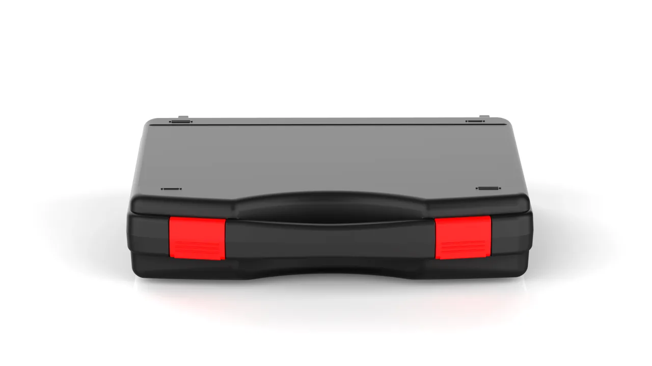
The changeover logic of a sanitary ware pressing line dictates its transport protection logic. When one line presses toilets, washbasins or squatting pans, the pressing mold and the press main ram sit on two completely different timelines. The mold comes off the machine every time the product changes, is bulky, has a precious parting line and carries a long list of loose inserts. The main ram piston rod is one of the most expensive single parts on the machine; its hard chrome or nitrided surface is exposed to shop air for years, and repairing a scratched rod costs far more than fitting a new cylinder. The two cannot share a case, and neither can be handled with a generic anti-rust, anti-dent mindset borrowed from ordinary machine spares.
The most awkward object is the green ceramic blank coming out of the press. A freshly demolded blank still carries a high water content, and the particles inside it are held together only by capillary force. Its flexural strength is on the order of a few hundred kilopascals, so a single drop onto a hard floor can chip an edge. Even when nothing breaks on the spot, microcracks already sit inside the body and only announce themselves after firing at 1200 degrees Celsius. By then the mold and the press have long since been installed at a new plant, so transport has to carry part of the responsibility for finding latent defects early.
JUNZHIJIA holds that the load-bearing face of a pressing mold must be fully decoupled from the protected face, and that the main ram rod must travel in a compartment of its own, packed to bare-part standard. JUNZHIJIA turns that principle into compartment rules, support rules and an acceptance checklist for press equipment cases, so that green blanks, molds and main rams each travel the distance from press to installation position under the humidity and force conditions each of them actually needs.
Table of Contents
- Latent Cracks Surfacing Only After Firing
- Detecting Parting Surface Bruising and Insert Shedding
- Plaster Mold Drying Shrinkage and Fracture Morphology
- Cracking at the Metal Core to Plaster Interface
- Scoring and Rust Grading on Main Ram Rods
- Residual Pressure and Residual Oil in the Cylinder Bore
- Vent Channel Blockage and Forming Surface Pressure Loss
- Platen Parallelism and Ram Stroke Lockout Allowances
- Ceramic Powder Dust Intrusion into Sealing Interfaces
- Green Blank Moisture Content and Transfer Loading
- Three Load Bearing Cases That Crush Flat Liners
- Compartment List and Packing Acceptance Signoff
- JUNZHIJIA Customization Workflow and Packing Documents
- Frequently Asked Questions FAQ
- Conclusion and Related Reading
Latent Cracks Surfacing Only After Firing
A pressed green blank passes through trimming, drying, glazing and saggarm loading before it reaches the kiln, and its strength changes the whole way. Straight off the press the moisture content sits between 15 and 22 percent and the body is in a wet strength state. After drying it falls below 1 percent and the blank enters a dry strength state. Between those two points lies a drying shrinkage transition zone, and that is where the body is most brittle.
A knock during transport does not necessarily produce a visible crack at the moment of impact. Release agent residue still coats the surface of a pressed blank, and the moisture distribution inside the body is uneven, so impact stress first creates microcracks in a local zone. Drying shrinkage then opens those microcracks, and by the time the piece reaches 1200 degrees Celsius, thermal stress has extended them into visible through-cracks. At that moment the blank is already on the customer line and the mold is already bolted to a new press.
| Stage | Moisture content | Flexural strength reference | Transport risk level |
|---|---|---|---|
| --- | --- | --- | --- |
| Just demolded | 15 to 22 percent | 0.2 to 0.8 MPa | High, any drop chips the edge |
| Drying transition | 5 to 15 percent | 0.5 to 1.5 MPa | High, shrinkage plus vibration |
| Dry blank | Under 1 percent | 2 to 6 MPa | Medium, latent cracks appear |
| After bisque firing, unglazed | 0 | 15 to 30 MPa | Low, stackable |
This table explains why JUNZHIJIA does not recommend shipping freshly demolded wet blanks in the same case as press components. Wet blanks need continuous ventilation and stable temperature, while press components need dryness and corrosion protection. Their humidity curves run in opposite directions. For the generic view of related parts, see Ceramic and Tile Machinery Cases.
For the blank layer itself, each blank sits in a compressible foam tray contoured to its outer profile, so the pressure bearing area lands on the support ribs of the body rather than on the thin walls. The tray also carries a ventilation channel that lets residual moisture escape in one direction, which stops condensation from forming on the blank surface inside a sealed case.
Detecting Parting Surface Bruising and Insert Shedding
The parting line of a pressing mold is the most accurate and most vulnerable surface on the whole tool. Once it is bruised by a hard object, every blank pressed afterwards carries a step or a misalignment at the matching position, and trimming cannot remove that error. The only remedy is to take the whole mold out of service.
Bruising shows up in three typical shapes, and the shape tells you which handling stage did the damage. Shape one, linear compression marks. The mark is straight and of consistent depth, meaning a hard edge inside the case touched the parting face directly and then slid across it once vibration excited the case. This is the most dangerous shape, because it proves the parting face was in contact with something hard for the entire journey, with no buffer gap anywhere in between. The diagnostic point is the continuous length of the mark: an impression longer than 30 mm is essentially proof of line contact.
Shape two, point chipping. The mark is a small conchoidal fracture concentrated on parting line corners or near the gate. Most of these come from a free drop impact during transport. They are single event damage, easy to spot visually, and usually do not affect pressing accuracy afterwards.
Shape three, ribbon wear. The mark is a wide shallow band with a tidy edge, most often caused by the parting face rubbing against the case wall liner during packing. This is progressive damage and the sneakiest of the three, because by the time the case is opened a shallow groove has usually already formed.
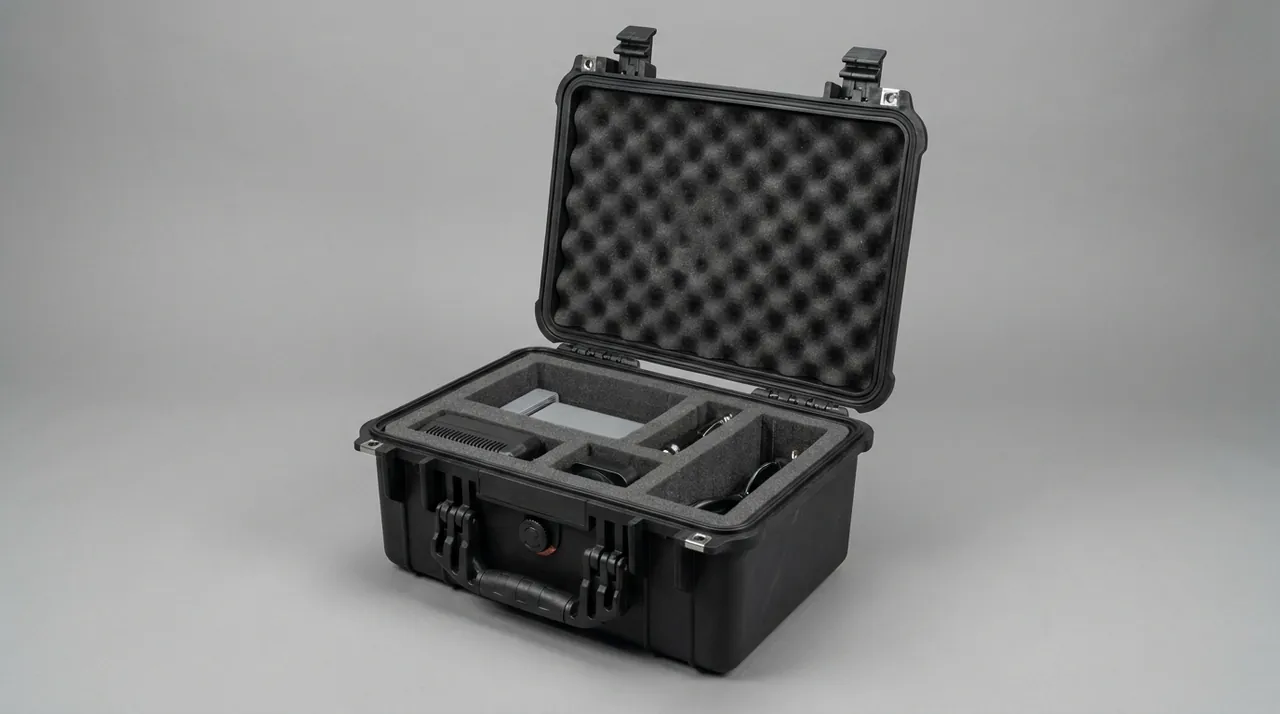
Three rules govern parting line protection. First, the parting face must not carry normal force from any direction. Second, the liner must leave at least 15 mm of clearance in the region corresponding to the parting face. Third, packing uses soft locating blocks to restrain translation of the mold, and those blocks must not press on the parting face itself. Detachable inserts get their own small compartments so a dropped insert cannot travel back into the parting line. Broader compartment detail for metal tooling is discussed in Casting Mold Transport Cases.
Plaster Mold Drying Shrinkage and Fracture Morphology
Sanitary ware pressing lines still use a great deal of plaster molds. Plaster molds normally hold 10 to 20 percent water by mass, with the balance being a mixture of hemihydrate and dihydrate calcium sulfate. The plaster dehydrates progressively during pressing and gives up crystal water during the drying stage, and that release comes with volumetric shrinkage.
Drying shrinkage sits in the 0.1 to 0.3 percent range, which sounds negligible until you apply it to a 1.5 m long pressing mold: 0.2 percent there is 3 mm of dimensional change. If a plaster model meets a serious drying cycle in transit, its parting line dimensions move with it, and once it is mounted on the press you may see pressing pressure climb out of range or blanks come out out of tolerance.
| Fracture type | Fracture color | Fracture texture | Usual cause |
|---|---|---|---|
| --- | --- | --- | --- |
| Fresh break | Bright white, faintly grey | Fine and dense | Instant impact during packing |
| Old break | Grey white, yellowed | Rough, clearly granular | Fatigue propagation after repeated loading |
| Delamination break | Layered color banding | Obvious layering | Interface degradation from wet dry cycling |
Delamination is the one to watch. It means the plaster already carried a microcracked layer before it was ever packed, and transport was only the last trigger. For those models JUNZHIJIA recommends a full body tap test before packing: strike along the perimeter of the parting line with a rubber mallet about every 200 mm and listen for a hollow response. A hollow zone is a degraded layer that must be assessed for repairability before the model goes anywhere near a case. Broader enclosure design notes for plaster and ceramic ware are in Glass Mold Cases.
Cracking at the Metal Core to Plaster Interface
Modern pressing molds widely use a metal core with plaster cast against it. The metal skeleton supplies stiffness and positioning accuracy, while the plaster layer supplies the forming face and the vent passages. In transport, this composite structure usually fails at the interface rather than in either material on its own.
The mechanism is a mismatch in thermal expansion and shrinkage. The metal core expands at roughly 11 times 10 to the minus 6 per degree Celsius, while plaster sits closer to 20 times 10 to the minus 6 per degree Celsius and shifts with moisture content while still wet. When a case swings through the day night temperature difference of a yard route, the two bodies deform out of step and the plaster layer sees shear and tension right at the bond line. Plaster is very strong in compression and very weak in tension, and that one sided stress state is exactly why cracks initiate at the interface.
Protection therefore works in two layers. The first is environmental control: nothing that generates a local heat source goes inside the case, and the case is never left standing in direct sun for hours. Plaster models should not share a compartment with metal parts, because metal has a small specific heat capacity, heats and cools quickly, and drives larger interface stress. The second layer is structural. Leave 5 to 8 mm of interface gap between metal core and plaster body, fill it with a flexible material such as foam or nonwoven fabric, and let the filler absorb relative displacement instead of forcing the brittle plaster to take it.
Once an interface crack exists, the plaster layer starts shedding flakes. Those flakes, if left loose inside the case, will abrade the parting line during subsequent vibration. So plaster packaging must include a removable liner bag or thin liner board inside the cavity, making the plaster body lift out as one piece rather than sitting directly on foam.
Scoring and Rust Grading on Main Ram Rods
The piston rod of a press main ram is the archetypal bare part. It has to reciprocate inside its guides, its surface is exposed directly to shop air, and it normally carries a hard chrome or nitrided layer. The protection target for this part is singular: no scratch and no corrosion of any kind may appear on the rod face during the entire journey.
| Grade | Description | Effect on later service | Recommended action |
|---|---|---|---|
| --- | --- | --- | --- |
| Grade 1 | Shallow hairline visible to the eye, under 10 microns deep | Local pressure concentration under the seal preload, harmless at first | Polish on site and use, assembly unaffected |
| Grade 2 | Longer than 20 mm, or 10 to 40 microns deep | May drag the seal during reciprocation and leak hydraulic oil inward | Reject the rod, polishing is not acceptable |
| Grade 3 | Deep longitudinal groove, chunk loss, or plating flaking | Rod geometry can no longer be restored, scrap outright | Replace the cylinder assembly |
Field depth judgment is simple. Draw a fingernail or a hard plastic card across the scratch; if it clearly catches, the scratch is Grade 2 or worse. That judgment must happen when the case is opened, not weeks later after the press is installed.
Rust needs an equally clear grading. Light rust is a uniform pale yellow powder that wipes away to leave bright metal, and it belongs to the removable category. Pitting corrosion is a local brown black spot that leaves a pit in the substrate after wiping, and it belongs to the non-removable category. A main ram rod with any pitting at all has to be scrapped at assembly level, because pitting means the surface has already suffered irreversible material loss.
The packing sequence is fixed. Wrap the rod face first in a corrosion inhibiting film, either vapour corrosion inhibiting film or waxed paper, then fit an EVA foam end cap, and finally add a rigid sleeve over the rod, in aluminium or injection moulded ABS. The sleeve is not there for cushioning. It exists so that hardware, fasteners and swarf inside the case can never touch the rod face. Layered treatment of high precision exposed parts is discussed in Precision Instrument Protective Cases.
Residual Pressure and Residual Oil in the Cylinder Bore
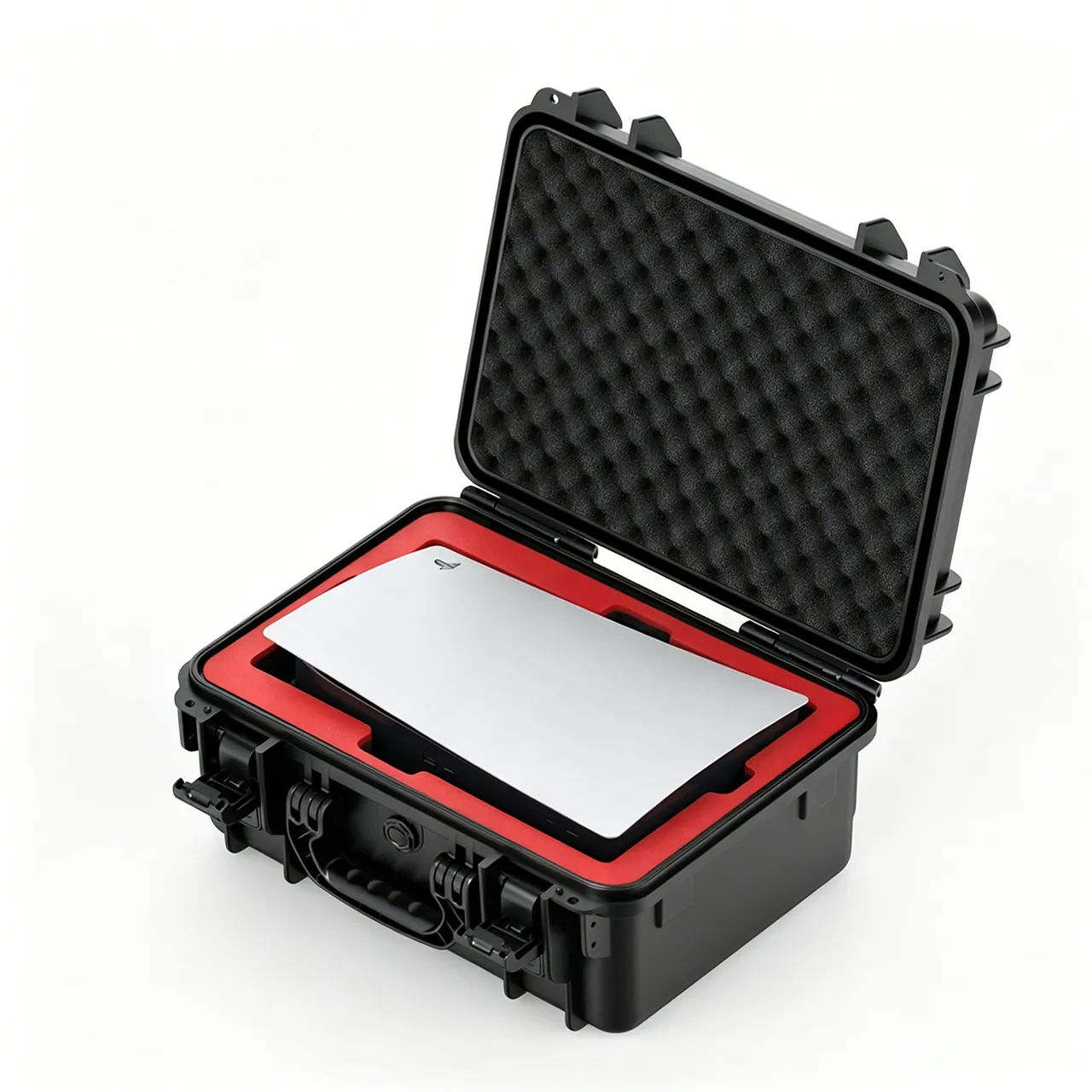
The hydraulic cylinder bore and the piston rod are the two ends of one main ram assembly. The bore interior needs corrosion protection while the rod outside needs scratch protection, so the two must be packed by different methods and must never share one cushioning scheme.
Residual pressure comes first. After assembly or overhaul, the bore may still hold hydraulic oil and stored energy in the accumulator. Even with the main ram powered down and unloaded, the bore can sit at roughly 0.5 MPa. Depressurizing before packing is mandatory: fully open the relief valve, crack the accumulator bleed valve, loosen the bore vent port, and confirm the gauge reads zero. Residual pressure is dangerous in transit because a vibrating case lets oil surge inside the bore, which can damage a seal or squeeze residual oil past the rod gland and contaminate the compartment.
Residual oil film picks up ceramic dust and turns into an abrasive paste. Stored upright, the oil collects at the lower port and sits against the seal lip, where it promotes corrosion. The procedure is to drain the oil, wipe the port and outer cylinder with a nonwoven cloth dampened in anhydrous ethanol, blow dry air through the bore, and then close it inside a barrier bag.
The bore wall itself is a honed surface with roughness around Ra 0.4 to 0.8 microns and a cross hatch pattern left by the honing tool. Honed surfaces are vulnerable to hard point contact and to abrasive grinding, so pack the bore lying horizontally rather than standing, which keeps residual oil and debris settling at the port instead of onto the honed wall. Close the bore with a soft plug; never drive a hard plastic plug into the port with a hammer. The general approach for hydraulic and pneumatic assemblies is covered in Hydraulic and Pneumatic Cases.
Vent Channel Blockage and Forming Surface Pressure Loss
The vent channels cut into a plaster mold are what let air escape as the slip fills the cavity, and their cross section is deliberately narrow. In transport they are the first thing to clog, because ceramic powder, release agent mist and plaster debris all settle where airflow is weakest. Once a vent channel is blocked, the next pressing cycle loses pressure at the forming surface, and the defect shows up as a local thin wall or a soft edge on the ware rather than as a fault you can see on the mold.
JUNZHIJIA treats vent channels as a protected interface, not as a cosmetic detail. Before packing, each vent is cleared with a soft bristle and a low pressure air pass, then the channel mouth is capped with a removable breather tab so powder cannot re-enter during the yard route. The cavity liner that carries the mold leaves a 3 to 5 mm relief around the vent band so nothing presses the channel closed.
A simple acceptance check is built into the packing documents: the packer records vent channel count and marks any that resisted clearing, and that note travels with the mold to the receiving plant. If a press later reports forming pressure loss on a specific cavity, the note tells the operator whether the channel was suspect before it ever left the sender. Related handling of fine powder interfaces is discussed in Ceramic and Tile Machinery Cases.
Platen Parallelism and Ram Stroke Lockout Allowances
A press platen and the main ram must stay parallel within a tight band, because the mold parting faces are machined to match that parallelism. If the ram locks out with a tilt, the mold sees uneven closing force and the parting line bruises on one side only. Transport has to protect two things at once: the platen flatness and the ram stroke end position.
Platen protection starts with how the case supports it. JUNZHIJIA uses three point support on the platen back, not edge clamping, so the platen cannot be bent by its own weight during a long sea route. The support pads are tuned to the platen stiffness, softer for thin platens and denser for thick, and they sit clear of any bolt hole so no local reaction force is introduced.
Ram stroke lockout is a separate control. Before packing, the ram is driven to a recorded mid stroke position and a lockout block is fitted between the rod end and the cylinder head, so vibration cannot drive the rod into either end stop. The lockout gap is recorded in the packing sheet, and the receiving plant checks it before the ram is freed. This prevents the rod from hammering the gland seal during a dropped corner, which is the usual cause of a weeping rod after installation. Broader alignment logic for press type equipment appears in Casting Mold Transport Cases.
Ceramic Powder Dust Intrusion into Sealing Interfaces
Ceramic body and glaze powder is fine enough to behave like a fluid when a case is shaken. It works into every seam, and the places it does the most damage are the sealing interfaces: the ram gland, the mold parting line and the cylinder bore port. Once powder is trapped against a seal, the next reciprocation grinds the seal like lapping compound.
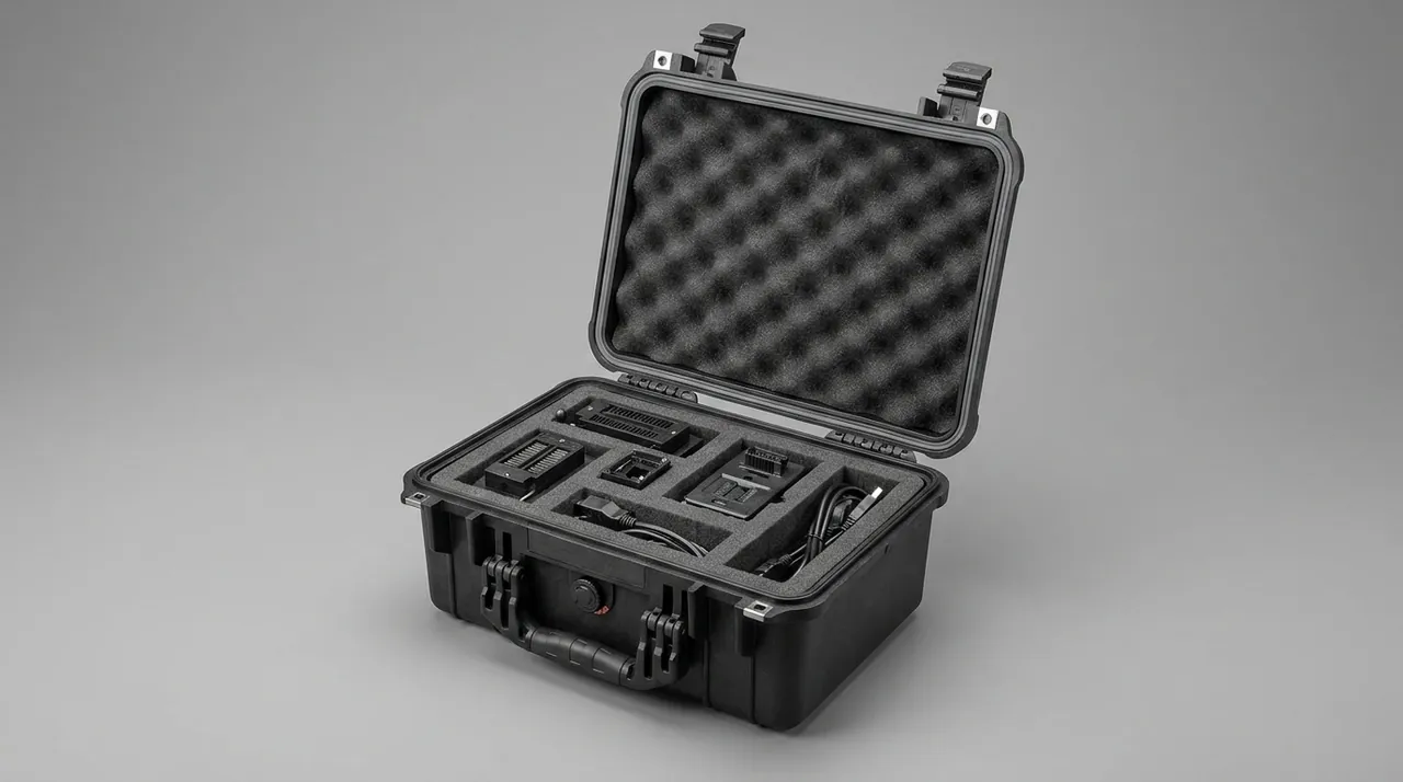
JUNZHIJIA stops intrusion at the source rather than cleaning it after. The mold and ram travel in sealed compartments with a positive pressure breather, so outside dust is pushed away from the seam instead of drawn in. Any surface that must stay open, such as a vent mouth or a gauge port, gets a removable cap rather than a wrap, because a wrap still leaves a gap edge where powder collects.
Inside the compartment, the liner is a closed bag system. The mold lifts out as one piece inside its liner bag, so powder that settles on the bag never reaches the parting face. The ram sleeve already provides a hard barrier, and the bag adds a second one at the compartment level. The packing sheet records whether the compartment was closed before the case was moved, because a case shifted before closure is the classic way dust gets past the first barrier. The general enclosure approach for dusty precision parts is in Precision Instrument Protective Cases.
Green Blank Moisture Content and Transfer Loading
The green blank and the press components must never share a humidity regime, so they are loaded as two separate transfer streams. Blanks go into ventilated trays with a one way moisture channel, while molds and rams go into dry sealed compartments. The loading sequence matters: blanks are set in first on a lower, stable layer, then the mold compartments are stacked above on their own support grid, so no blank tray ever carries the weight of a steel mold.
Moisture content is checked at the dock, not assumed. A handheld moisture meter reads the blank surface, and any blank above the dry strength threshold travels in a ventilated lane with desiccant only at the lane mouth, never sealed with the components. The transfer document records the reading and the lane, so a later firing defect can be traced to the blank state at dispatch.
Loading also respects orientation. Blanks sit support rib down, never on a thin wall, and the tray is contoured so the rib pedestals take the load. Molds are blocked against translation with soft locators that do not touch the parting face. The receiving plant reverses the sequence: it opens the mold compartments first for a clean environment, then the blank lane, because the most sensitive surfaces should be exposed last. Comparable transfer loading discipline for wet and dry parts is in Glass Mold Cases.
Three Load Bearing Cases That Crush Flat Liners
Flat liners fail in three repeatable ways, and all three come from getting the load path wrong rather than from weak material. The first is edge loading, where a mold rests on its parting line edge instead of on purpose built support ribs, and the liner compresses flat under that line. The second is point loading, where a loose insert or a bolt head digs into the liner at one spot and the compression there runs past the material limit. The third is stacked loading, where a second compartment is placed directly on a thin liner without a load spreader, and the lower liner sees the upper compartment weight through the whole route.
JUNZHIJIA designs the liner to fail none of these. Support ribs are matched to the parting line so the mold sits on its strong section, not its edge. Loose inserts get their own small compartment so they cannot become point loads. And every stacked compartment rides on a rigid spreader grid, never on the liner of the case below.
The acceptance check is visual and simple. After packing, the packer presses the liner at the load points and confirms it returns, then the case is tilted to simulate handling and rechecked. A liner that stays flat under finger pressure at the load point is already wrong before the case moves. The crush flat failure mode is covered more broadly in Hydraulic and Pneumatic Cases.
Compartment List and Packing Acceptance Signoff
A sanitary ware press case is really a set of compartments, and the packing document is the signoff that each one was packed to its own rule. The compartment list names every cavity, what it holds, and the specific control attached to it: the mold cavity with its parting line clearance, the ram compartment with its bare part sleeve, the bore barrier bag with its vent record, the insert mini compartments, and the blank lane with its moisture reading.
Acceptance is a step by step signoff, not a single stamp. The packer records, for each compartment, that the parting face had clearance, that the rod sleeve was fitted, that the bore was depressurized and wiped, that inserts were bagged, and that the blank lane moisture was within range. Each line is initialed, and the sheet travels with the case.
The receiving plant uses the same sheet to drive its opening sequence. It opens the mold compartment first into a clean area, checks the parting line, then the ram, then the bore, and only then the blanks. Any discrepancy is written against the matching compartment line, so responsibility is clear and the next dispatch can correct it. The document template itself is part of what JUNZHIJIA delivers, and it can be aligned to a customer quality system on request. See Casting Mold Transport Cases for the comparable mold compartment structure.
JUNZHIJIA Customization Workflow and Packing Documents
JUNZHIJIA builds sanitary ware press cases around the actual part drawings rather than a standard box. The workflow starts with a drawing review where the mold parting line, the ram stroke and the bore port positions are mapped against the case interior. A sample case is then trial fitted to the real mold and ram, so clearance and support are proven before production tooling is cut.
Customization covers three levels. Level one is compartment layout: cavities are placed to the part geometry, with the parting face always clear. Level two is material: liner density, barrier film and sleeve material are chosen to the corrosion and dust exposure of the route. Level three is documentation: the packing sheet, the compartment list and the opening sequence are written to the customer template, including any marine or class society notes.
OEM and ODM work is supported, and the cases can carry the customer brand as agreed. The deliverable is not just a box but a repeatable packing process: once the sample is accepted, every following case is built to the same drawing and signed off on the same sheet. That repeatability is what lets a plant receiving presses at several sites trust that each case was packed the same way. The broader custom workflow for mold type equipment is in Ceramic and Tile Machinery Cases.
Frequently Asked Questions FAQ
Q: Why must the green blank and the press components travel in separate humidity regimes?
A: A freshly demolded blank carries 15 to 22 percent moisture and sits in a wet strength state, while press molds and main ram rods need a dry, corrosion free environment. If they share one case, the blank keeps the local air humid and the mold parting line and the ram chrome face sit in that humidity for the whole route, which is exactly the condition that grows rust and softens the plaster model. The two also need opposite handling: blanks want ventilation and stable temperature, components want sealed dryness and desiccant. JUNZHIJIA splits them into two transfer streams, blanks in ventilated trays with a one way moisture channel on a lower stable layer, molds and rams in sealed compartments above on their own support grid. A handheld meter reads blank moisture at the dock and the reading is recorded on the transfer document, so a later firing defect can be traced to the blank state at dispatch. The loading sequence is then reversed at receipt, opening the sensitive mold and ram compartments first into a clean area before the blank lane is exposed. That separation is the single most effective control against latent cracking and corrosion on a sanitary ware press line.
Q: How do you detect parting surface bruising before it ruins production?
A: Parting line bruising shows in three shapes and the shape names the handling stage that caused it. Linear compression marks are straight and even depth, proof the parting face rode against a hard case surface with no buffer gap for the whole journey, and any mark longer than 30 millimetres is essentially proof of line contact. Point chipping is a small conchoidal fracture at corners or near the gate, almost always a single free drop impact, easy to see and rarely harmful to accuracy. Ribbon wear is a wide shallow band with a tidy edge, caused by the parting face rubbing the liner during packing, and it is the sneakiest because a shallow groove has usually already formed by the time the case is opened. Detection is visual and tactile: run a fingernail or a hard plastic card across the parting face and feel for any catch, and inspect under raking light because a straight even mark hides in flat light. Three packing rules then govern it: the parting face carries no normal force from any direction, the liner leaves at least 15 millimetres of clearance at the parting region, and soft locators restrain translation without touching the face. Detachable inserts travel in their own compartments so a dropped insert cannot return to the parting line.
Q: Why do plaster molds crack at the metal core interface during transport?
A: A modern pressing mold casts plaster against a metal core, and the two materials expand and shrink at different rates. The metal core moves at roughly 11 times 10 to the minus 6 per degree Celsius, while plaster sits near 20 times 10 to the minus 6 and also shifts with moisture while it is still wet. On a yard route the case swings through a daily temperature difference, the core and the plaster deform out of step, and the plaster layer meets shear and tension right at the bond line. Plaster is strong in compression but weak in tension, so cracks start at that interface rather than inside either material. Protection works in two layers. Environmentally, nothing that makes local heat goes inside the case and the case is never left in direct sun, because metal has a small heat capacity and drives larger interface stress if it shares a compartment with plaster. Structurally, leave 5 to 8 millimetres of interface gap filled with flexible foam or nonwoven fabric so the filler absorbs relative movement instead of the brittle plaster. Once an interface crack exists the plaster sheds flakes that abrade the parting line during vibration, so the cavity uses a removable liner bag that lifts the plaster body out as one piece. A perimeter tap test before packing catches a degraded layer early.
Q: How is a main ram rod graded for scratches and rust before acceptance?
A: The main ram rod is the archetypal bare part, a hard chrome or nitrided face exposed to shop air, and the protection target is absolute: no scratch and no corrosion on the rod face for the entire journey. Scratches grade by depth and length. Grade 1 is a hairline under 10 microns that a fingernail barely catches, polished on site and used. Grade 2 is longer than 20 millimetres or 10 to 40 microns deep, which can drag the seal during reciprocation and leak oil, so the rod is rejected. Grade 3 is a deep longitudinal groove, chunk loss or plating flake, and the cylinder assembly is scrapped. The field test is to draw a fingernail or hard plastic card across the scratch; a clear catch means Grade 2 or worse, and that judgment is made when the case is opened, not weeks later. Rust grades the same way. Light rust is a uniform pale yellow powder that wipes to bright metal and is removable. Pitting is a local brown black spot that leaves a pit after wiping and is not removable, and any pitting at all scraps the rod at assembly level because the surface has lost material for good. The packing sequence then wraps the rod in vapour corrosion inhibiting film or waxed paper, fits an EVA foam end cap, and adds a rigid aluminium or ABS sleeve so nothing inside the case can touch the face.
Q: Why must the cylinder bore be depressurized and wiped before packing?
A: The cylinder bore and the piston rod are the two ends of one ram assembly, but they need opposite protection, so they are packed by different methods and never share one cushioning scheme. Residual pressure comes first. After assembly or overhaul the bore may still hold oil and stored energy in the accumulator, and even with the ram powered down it can sit near 0.5 MPa. Depressurizing is mandatory: open the relief valve, crack the accumulator bleed, loosen the bore vent, and confirm zero on the gauge, because a vibrating case lets oil surge and damage a seal or squeeze past the gland. Residual oil film then picks up ceramic dust and turns into an abrasive paste, and stored upright it collects at the lower port against the seal lip and promotes corrosion. The procedure drains the oil, wipes port and cylinder with anhydrous ethanol on nonwoven cloth, blows dry air through the bore, and closes it in a barrier bag. The bore wall is a honed surface around Ra 0.4 to 0.8 microns with a cross hatch, vulnerable to hard point contact, so the bore is packed lying down rather than standing, keeping debris at the port instead of on the wall, and closed with a soft plug rather than a hammered hard one. That discipline keeps the honed surface intact through the route.
Q: What causes vent channel blockage and how is it prevented?
A: Vent channels in a plaster mold are narrow by design so air escapes as slip fills the cavity, and that same narrow cross section is the first thing to clog in transport. Ceramic powder, release agent mist and plaster debris all settle where airflow is weakest, and once a channel blocks the next pressing cycle loses pressure at the forming surface, showing as a thin wall or soft edge on the ware rather than a visible mold fault. JUNZHIJIA treats vents as a protected interface. Before packing each vent is cleared with a soft bristle and a low pressure air pass, then capped with a removable breather tab so powder cannot re-enter on the yard route. The cavity liner leaves a 3 to 5 millimetre relief around the vent band so nothing presses the channel closed, and the packing document records vent count and flags any that resisted clearing. That note travels with the mold to the receiving plant, so if a press later reports forming pressure loss on a cavity, the operator knows whether the channel was suspect before dispatch. The control is cheap and the payoff is direct: a blocked vent is far easier to prevent at packing than to diagnose after a firing defect reaches the customer line. Fine powder interface handling is discussed in related ceramic machinery cases.
Q: How do you stop ceramic powder from reaching the sealing interfaces?
A: Ceramic body and glaze powder is fine enough to flow like a fluid when a case is shaken, and it seeks the sealing interfaces: the ram gland, the mold parting line and the bore port. Once trapped against a seal, the next reciprocation grinds it like lapping compound. JUNZHIJIA stops intrusion at the source. The mold and ram travel in sealed compartments with a positive pressure breather, so outside dust is pushed away from the seam instead of drawn in, and any surface that must stay open gets a removable cap rather than a wrap, because a wrap still leaves a gap edge where powder collects. Inside, the liner is a closed bag system: the mold lifts out as one piece inside its bag, so powder settling on the bag never reaches the parting face, and the ram sleeve adds a second barrier at the compartment level. The packing sheet records whether the compartment was closed before the case moved, because a case shifted before closure is the classic way dust passes the first barrier. The acceptance check is then repeated at receipt, reopening each compartment and confirming the seal faces are still clean before the part is freed. That two barrier, closed before move discipline is what keeps ceramic powder out of the places it does the worst damage.
Q: What does the JUNZHIJIA packing signoff actually guarantee?
A: The packing signoff is a compartment by compartment record that each cavity was packed to its own rule, naming every compartment, what it holds and the control attached: the mold cavity with its parting line clearance, the ram compartment with its bare part sleeve, the bore barrier bag with its vent record, the insert mini compartments, and the blank lane with its moisture reading. For each, the packer records that the parting face had clearance, the rod sleeve was fitted, the bore was depressurized and wiped, inserts were bagged, and the blank moisture was in range, and each line is initialed. The receiving plant uses the same sheet to open the mold first into a clean area, then the ram, then the bore, then the blanks, writing any discrepancy against the matching compartment line. What it guarantees is repeatability and traceability: every case built to the accepted sample is packed the same way and any defect ties to a named compartment and a signed line. That is the real product JUNZHIJIA delivers, a packing process a plant can trust across several receiving sites.
Conclusion and Related Reading
JUNZHIJIA separates blanks, molds and rams into their own humidity and protection regimes so latent cracks and corrosion never reach the customer line.
Related Reading