

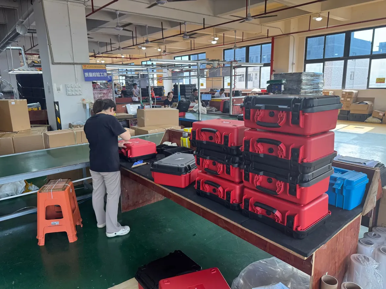
Quick answer: A semiconductor spares case fights itself on one liner: clean needs no shedding, ESD needs under 10⁹ Ω, and only dissipative EVA passes both.
Table of contents
- Why the two requirements collide
- Particle counts and a liner that does not shed
- Choosing between conductive and dissipative
- Equal potential and the grounding stud
- FAQ
1. Why the two requirements collide
One 48 L semiconductor spares case was measured twice. With plain PE foam the 0.3 μm count inside rose from 1.2×10⁵ to 8.6×10⁵ particles/m³ within 30 s of opening the lid. With conductive foam the count fell, but black transfer marks appeared on the wall: carbon black rubbed off the filler.
The conflict is mechanical. Cleanliness asks whether a material releases particles, ESD asks whether charge can cross its surface: one needs a stable skin, the other needs filler bridging the resin, and that filler-resin interface is where powder grinds free.
The two tests also look in different directions: shedding measures wear between surface, air and rubbing partner, while surface resistance measures how hard current finds its path. Neither substitutes for the other.
A sealed box amplifies the problem. The tighter the lid, the larger the pressure step at opening and the more particles leave with the air. ESD then demands the liner sit against the wall to share potential, and closer contact means more rubbing area and more powder.
| Option | Surface resistance | Shedding | Verdict |
|---|---|---|---|
| Plain PE foam | Above 10¹⁴ Ω | Heavy, dust on opening | Not usable |
| Conductive foam | 10⁴–10⁶ Ω | Slight, carbon transfers | Metal parts only |
| Dissipative EVA | 10⁶–10⁹ Ω | No visible shedding | First choice |
| Antistatic fabric | 10⁶–10⁹ Ω | Sheds fibres | Not advised |
2. Particle counts and a liner that does not shed
The baseline at the opening station is ISO Class 5, meaning no more than 3520 particles/m³ at 0.5 μm and above. Inside counts are taken against that background: rest the case in the area for 2 h, open the lid for 30 s, and sample 100 mm above the opening 3 times on a 0.3 μm channel.
Closed cells are the first gate. Open-cell foam carries pores of 0.3 to 1.0 mm that swallow particles and release them on the next handling; closed-cell EVA has sealed walls, wipes clean in one pass, and still releases fewer than 10 fibres per sheet after 50 wipes.
Edge finishing is the second gate. Die-cut edges crumble in service, so the liner is heat-sealed at the edge or buried in a groove so the cut face never meets moving air.
Joints are the third gate. Every seam wider than 0.5 mm collects dust, so a one-piece liner is held at ±0.3 mm and pressed in with interference rather than glued.
Wipeability decides whether any of it lasts. Inner corners run R3 or larger, base corners are never square, and the liner face is grained rather than flocked so a cloth lifts dust without lifting fibres.
3. Choosing between conductive and dissipative
The dividing line sits at 10⁶ Ω. From 10⁴ to 10⁶ Ω the material is conductive, draining charge fast, which suits metal parts, jigs and empty trays. From 10⁶ to 10⁹ Ω it is dissipative, bleeding charge slowly, which suits chip trays, connectors and sensor modules.
Wrong choices cost differently: a conductive liner under a sensitive device drains fast enough to damage a gate oxide, while a dissipative liner under bare metal leaves charge lingering for 10 s or more.
Mixing works if the box is zoned: metal jigs on the conductive side, chip trays on the dissipative side, with a conductive edge strip tying both liners into one potential.
| Grade | Surface resistance | Typical liner | Spares |
|---|---|---|---|
| Conductive | 10⁴–10⁶ Ω | Carbon-filled PE | Metal jigs, empty trays |
| Dissipative | 10⁶–10⁹ Ω | Fibre-loaded EVA | Chip trays, connectors |
| Insulating | Above 10⁹ Ω | Plain EPE | Not for this duty |
Measure on the finished box, never on a raw sample. Pressing the liner into the body stretches it 5% to 8%, pulling the filler network apart: the same sheet reads 10⁷ Ω flat and can jump to 10¹⁰ Ω once fitted, which drops it out of the dissipative band.
4. Equal potential and the grounding stud
Liner and body must share one potential, held within 10 V, with a bond resistance under 10³ Ω. A copper foil strip on the liner back, pressed down by a 0.75 mm² braid from the stud in the side wall, does the job.
The grounding stud gets its own position on a semiconductor spares case and never shares hardware. Stainless body, nickel-plated contact face, and a 1 MΩ resistor in series to limit discharge current so an operator cannot take a shock.
Keep the stud away from the handle and latches. A hand reaches the handle first, and a stud sitting in the web of the thumb drains the person before the box, which routes body charge straight into the load area.
Friction during handling is the hardest part to control. Liner and wall rub continuously under transport vibration, and plain material builds 2 kV while a dissipative liner holds it under 200 V, with the gasket adding a buffer so the two faces never slide directly.
Two lines are fixed: replace the stud spring every 12 months, and measure the braid every quarter, swapping the lead once it passes 10³ Ω.
Conclusion
A semiconductor spares case is signed off on two lists. The clean list holds three lines: closed-cell liner, fewer than 10 fibres per sheet after 50 wipes, and an inside 0.3 μm peak under 3 times the 3520 particles/m³ background measured 30 s after opening. The ESD list holds three more: liner resistance between 10⁶ and 10⁹ Ω, liner-to-body potential within 10 V, and a bond under 10³ Ω through a 1 MΩ stud. Any line failing sends the box back to non-sensitive duty. Put all six into the technical agreement and require the supplier to test the finished box, not a raw sheet, because the 5% to 8% stretch of fitting is what pushes a good material out of its band.
This article discusses container-side specifications and design implications only, and does not cover any handling, loading or use of the contents.
Related Reading
- Static-safe case design as a whole
- Materials and structure of ESD liners
- Shielding bags versus shielding cases
- Cleaning requirements for cleanroom equipment cases
Related Products
- 8 Series — Gun Cases; Military Equipment Cases; Camera Equipment Cases; Drone Cases; Watch Cases; Knife Cases; First Aid Cases; Electronics Equipment Cases
- WL8-2812 PP Gun Case — model WL8-2812
- All protective cases and toolboxes: 7 series, 158 models