

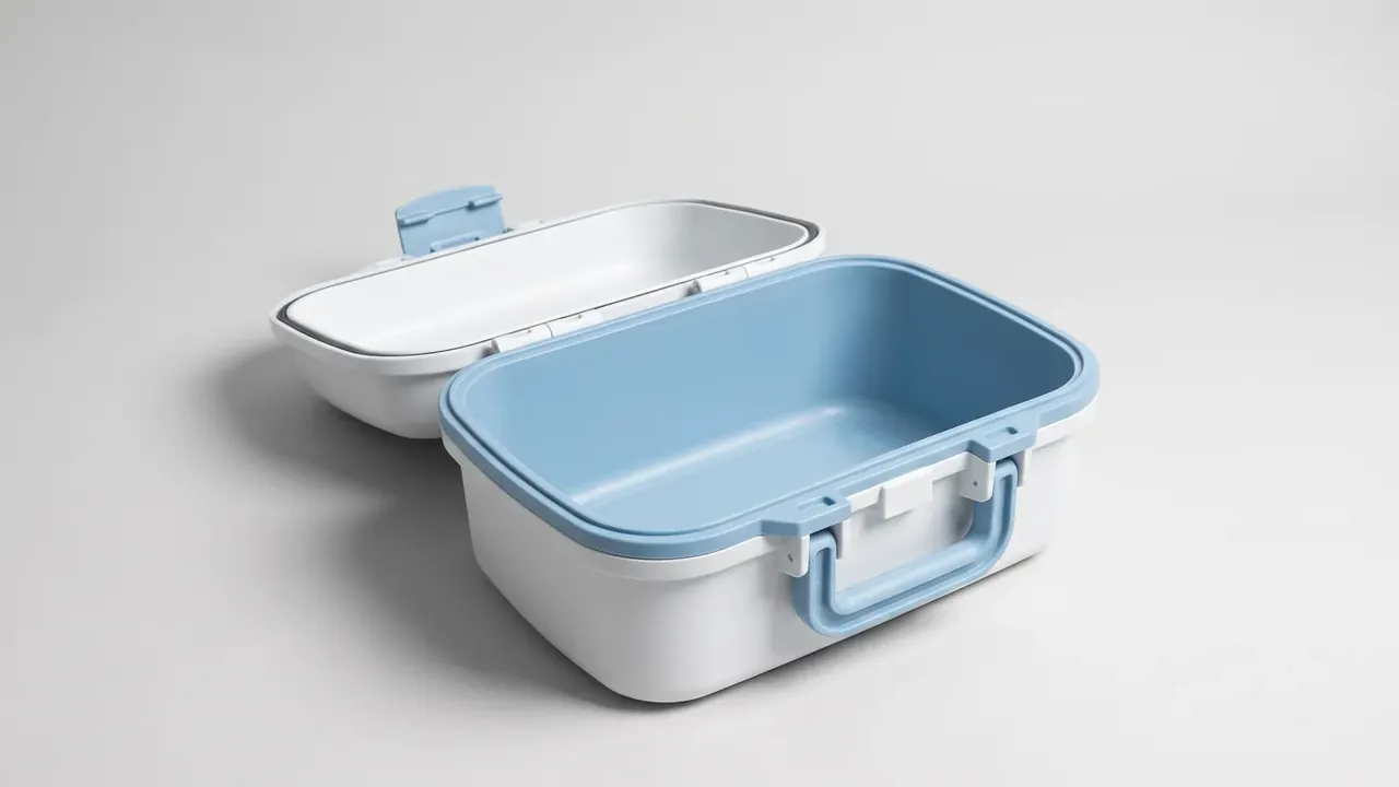
Quick answer: A Sensor Equipment Case sets a 6.4 mm gasket-groove lip and 0.28 mm rim flatness; at -18 kPa held 20 min, the pressure drop stays under 0.16 kPa.
Table of contents
- Gasket-Groove Lip Height in a Sensor Equipment Case
- Flatness at the Case Mouth
- Pressure Drop After Twenty Minutes Under Vacuum
- Lid Gap After Re-Pressurising
- Setting the Lip Height for a Production Batch
- FAQ
1. Gasket-Groove Lip Height in a Sensor Equipment Case
Draw the case mouth down to minus eighteen kilopascals, and whether the decay trace flattens out comes down to one pairing: the lip height of the groove against the flatness of the rim.
The lid of a Sensor Equipment Case carries a moulded groove whose raised lip bears on the seal ring, with the lip set at 6.4 mm. At 530 x 375 x 205 mm outside, 465 x 315 x 150 mm inside and a 4.2 mm wall, the groove and the lid face come off one tool, so altering the lip means re-cutting the whole lid mould.
Three lip heights go to trial first. A 5.8 mm lip loses pressure the moment the vacuum starts, a 7.0 mm lip pushes the lid gap past its limit, and 6.4 mm holds the twenty-minute drop below 0.16 kPa.
| Lip height grade | Nominal lip | Groove allowance | Behaviour under vacuum |
|---|---|---|---|
| Short | 5.8 mm | 0.9 mm | Loses pressure at the pull, ring uncompressed |
| Middle | 6.4 mm | 1.3 mm | Drop still under 0.16 kPa at twenty minutes |
| Tall | 7.0 mm | 1.8 mm | Lid edge lifts, gap passes 0.25 mm |
2. Flatness at the Case Mouth
Rim flatness is held to 0.28 mm in a Sensor Equipment Case, covering the ring where lid and body meet. Any high spot there leaves the seal ring slack at that stretch, and under vacuum air takes exactly that route, dragging the whole decay trace upward.
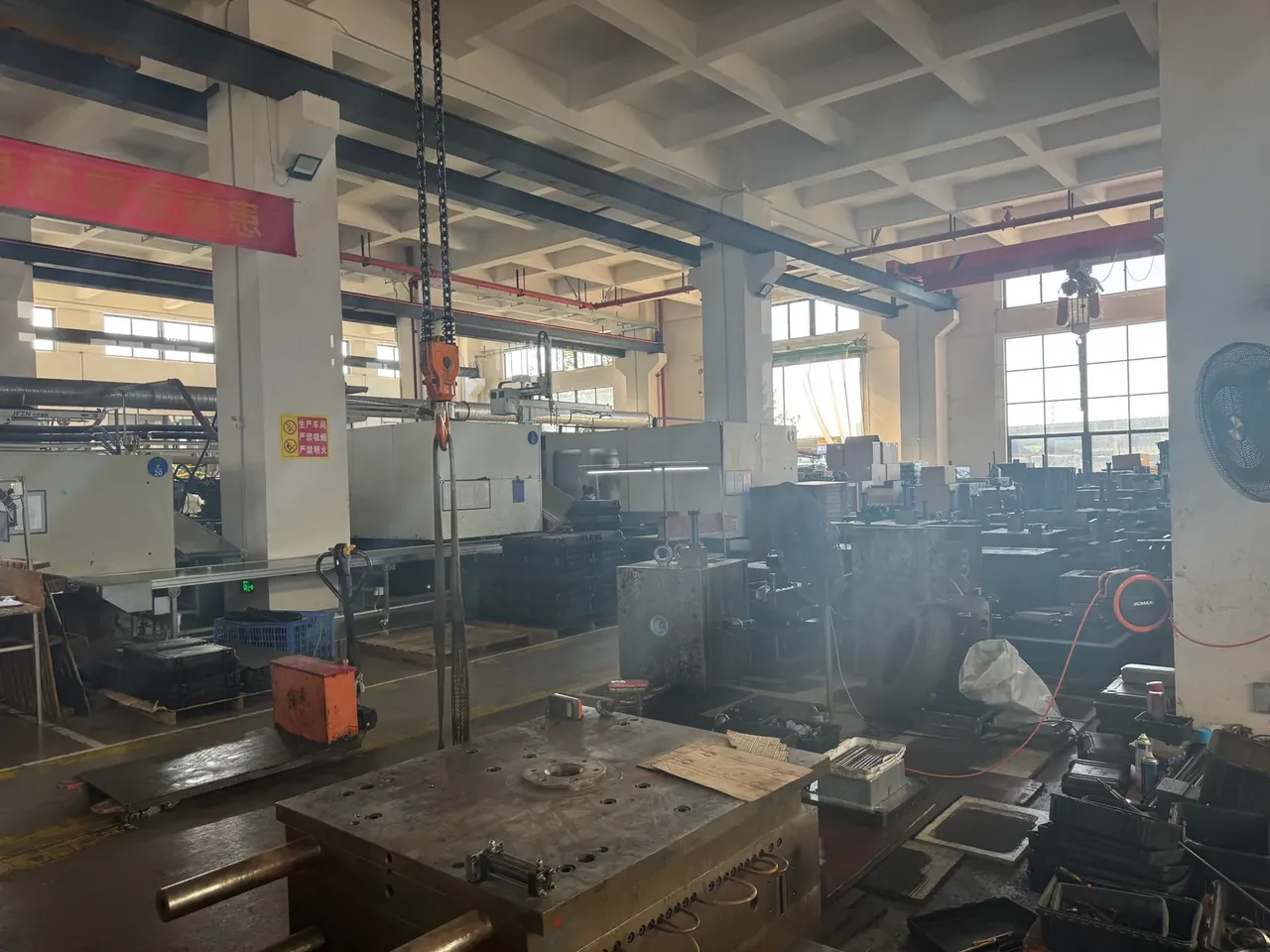
The airtight bench sets the shell on four matched blocks and sweeps a straightedge around the mouth; 0.28 mm is the most it may ripple. Thickened corners ring the mouth of a Sensor Equipment Case, and the corner-to-straight junction is where ejection tends to bow the part, which is where bad readings cluster.
Flatness and lip height are marked as two separate dimensions yet share one lid tool. Touch either and the bench has to pull again, since there is no way to move just one number.
3. Pressure Drop After Twenty Minutes Under Vacuum
The bench draws the mouth to -18 kPa and holds for 20 min with no top-up and no latch released.
Pull to -18 kPa and let it steady before starting the clock. Log at minute five to check the slope narrows. Log again at minute ten, when the trace should begin to flatten. Record the end point at minute twenty, and subtract the pull value to get the drop used for judgement.
| Hold interval | Chamber pressure | Cumulative drop | Logging step |
|---|---|---|---|
| Pull, 0 min | -18 kPa | 0.00 kPa | Gauge zeroed at -18 kPa |
| Mid, 10 min | -18.09 kPa | 0.09 kPa | Note the slope, check it narrows |
| Full, 20 min | -18.15 kPa | 0.15 kPa | Still under 0.16 kPa to keep the grade |
Both the empty 4.9 kg shell and the 11 kg loaded shell get a pull. A Sensor Equipment Case has to pass in both states.
4. Lid Gap After Re-Pressurising
At the end of the hold, bring the chamber back to atmospheric and give the shell a rest before measuring the closed gap.
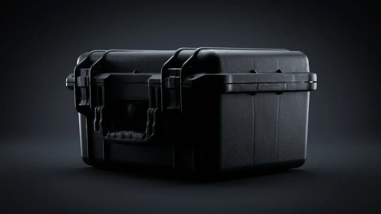
The lid gap is capped at 0.25 mm, tried segment by segment with a feeler gauge. A Sensor Equipment Case is pulled a second time after re-pressurising, and the drop has to match the first run before the unit is steady; a wide gap between runs points to a sink at the lip root or a bowed corner, and the lid tool goes back for inspection.
| Drop reading | Matching lip | Re-pressurised gap | Lip decision |
|---|---|---|---|
| 0.21 kPa | 5.8 mm | 0.28 mm | Over the line, whole batch back for retool |
| 0.15 kPa | 6.4 mm | 0.22 mm | Set as the production-batch value |
| 0.11 kPa | 7.0 mm | 0.31 mm | Gap too wide, tall lip still rejected |
5. Setting the Lip Height for a Production Batch
A production run shares one lid tool, so the lip cannot be chosen per box at the bench.
The lip value is fixed at the shortest grade whose twentieth-minute drop still reads below 0.16 kPa; any taller lip goes back for a retool.
A batch is judged by how tightly the drops cluster across different shells at one lip height. After 4400 open-close cycles another pull is needed, because wear at latches and hinges eases the lid edge loose. Two seal rings at 19 percent compression, with IP66 only as a typical benchmark, are environmental items logged in their own column, not folded into the lip record. JUNZHIJIA keeps a lid-tool trial sheet with every Sensor Equipment Case, so the bench log shows which lip a given shell carries.
Conclusion
Choosing a lip height for a Sensor Equipment Case comes back to one decay line under minus eighteen kilopascals over twenty minutes, plus the 0.25 mm lid gap after re-pressurising. Freeze those two sets of readings on the tool drawing and the whole run of Sensor Equipment Case units is judged by the same reject threshold.
Related Reading
- Electronic Equipment Case Specs: From 14 kg Load to a 6 mm Wall
- Should a Protective Case Use Dividers or Foam Liner? Divider vs. Foam Comparison Table and Selection Advice
- Case Gasket Groove: Single vs Double Lip
- Shockproof Case for Precision Equipment
- Microscope Equipment Transport Case
Related Products
- 8 Series — Gun Cases; Military Equipment Cases; Camera Equipment Cases; Drone Cases; Watch Cases; Knife Cases; First Aid Cases; Electronics Equipment Cases
- WL8-2812 PP Gun Case — model WL8-2812
- All protective cases and toolboxes: 7 series, 158 models