

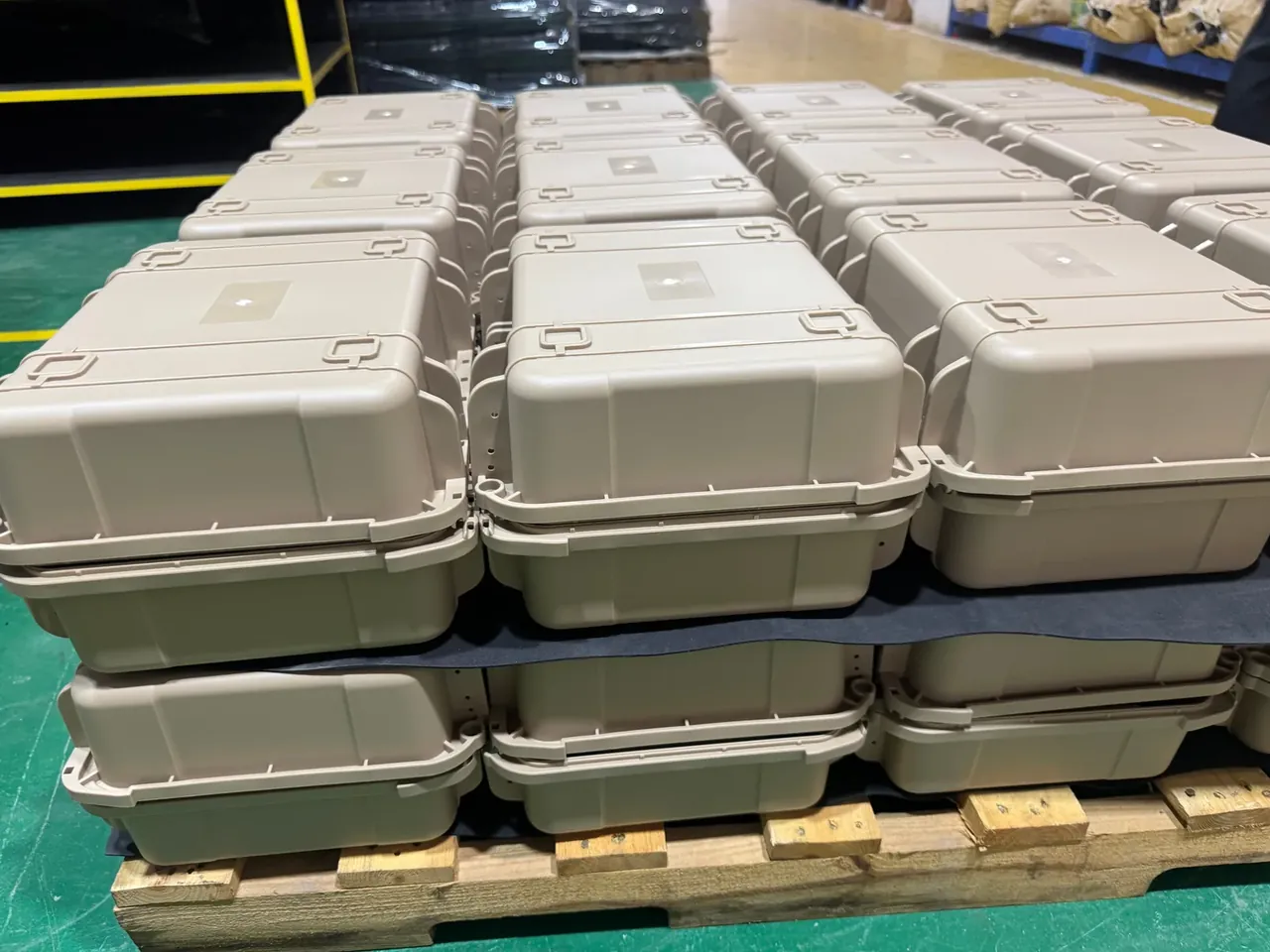
Quick answer: A stacking locator holds three layers only when 6 mm of depth, 3° of taper and 1.2 mm of side clearance keep top-layer travel near 4.8 mm.
Table of contents
- Three Numbers Behind a Stacking Locator
- Where 4.8 mm of Cumulative Offset Comes From
- Why the Third Layer Slides First
- Putting the Numbers on a Drawing
- FAQ
1. Three Numbers Behind a Stacking Locator
A stacking locator is the four shallow recesses moulded into a case lid. The feet of the case above drop in, and the recess walls block sideways movement. The stacking locator carries no vertical load, which travels through base ribs and posts; its only job is to stop the upper case shifting when a forklift turns.
Three dimensions decide whether it does that job: depth, taper and side clearance. Depth is the engagement height. Below 4 mm the upper case climbs out as soon as it moves sideways, since only a line of wall stays in contact; above 9 mm the recess traps air and lift-off force rises from 18 N to 42 N.
Taper is a compromise between mould release and self-centring. A steeper wall guides the case down more easily but leaves a slanted contact line with less shear area. At 3° over 6 mm of depth, the wall gives up 0.315 mm per side, which recovers only 26% of the 1.2 mm clearance.
The 1.2 mm clearance is a sum, not a choice: 0.4 mm of mould shrinkage, 0.3 mm of variation in foot height and 0.5 mm of thermal movement between −20 °C and 60 °C. When one of the three drifts, the case sits off-centre from the day it ships. Squeeze the clearance under 0.6 mm and operators start squaring each case by hand, taking cycle time from 8 s to 14 s.
| Depth mm | Engagement mm | 3° taper relief mm | Lift-off N | Layers |
|---|---|---|---|---|
| 4 | 4 | 0.210 | 18 | 2 |
| 6 | 6 | 0.315 | 26 | 3 |
| 9 | 9 | 0.472 | 42 | 3, needs draft |
2. Where 4.8 mm of Cumulative Offset Comes From
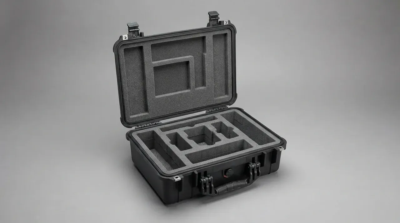
Side clearance of 1.2 mm lets the case move that far in any direction at the joint. Two layers have one joint, so the top case floats within ±1.2 mm. Three layers have two joints in series, and the free travel adds up to a 4.8 mm range.
That sum is measurable. Stack three 22 kg cases on a granite plate flat to 0.5 mm, probe the top corners against the bottom with feeler gauges: 0.9 mm, 1.4 mm, 2.2 mm and 2.4 mm.
| Layers | Joints in series | Max offset mm | Total travel mm | Acceleration gain | Verdict |
|---|---|---|---|---|---|
| 2 | 1 | 1.2 | 2.4 | 1.0× | stable |
| 3 | 2 | 2.4 | 4.8 | 1.7 to 2.0× | critical |
| 4 | 3 | 3.6 | 7.2 | 2.4× | strap it |
The 7.2 mm in the third row exceeds the 6 mm depth: the foot is half out of its recess and one more layer has nothing left to work with. That is why most stacking rules stop at three layers.
Against a 6 mm depth, 4.8 mm is 80%: at the 2.4 mm extreme one wall keeps 3.6 mm of engagement, and the 3° taper lifts the case by 0.13 mm.
3. Why the Third Layer Slides First
Dry friction between polypropylene surfaces runs 0.28 to 0.32, so 0.30, with cornering checked at 0.3 g. The two match, so every joint sits exactly at its sliding limit: friction supplies 0.30 times the weight above, inertia the same.
Friction does not vary with layer count; the difference comes from how the clearances are arranged. With one joint the top case is tied to the base through a single gap and acceleration passes straight up; with two joints the case bounces between two free travels and the measured gain is 1.7 to 2.0 times, call it 1.9. Multiplying 0.3 g by 1.9 gives 0.57 g, past the 0.30 friction limit, and layer three moves.
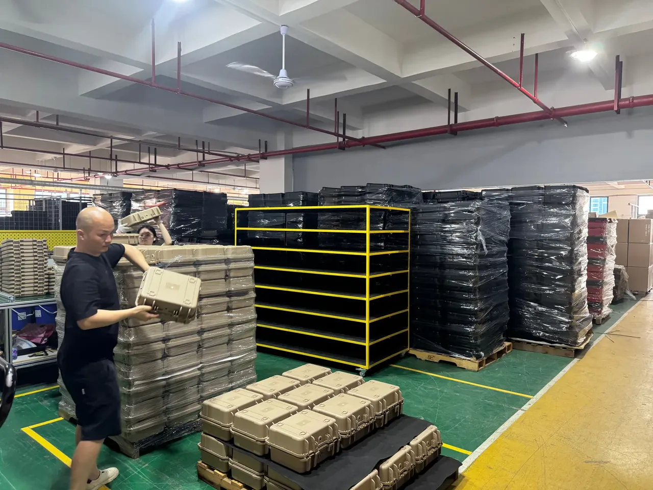
In a four-high stack the bottom case carries 66 kg, and 0.3 g turns that into 194 N over four walls of 6 mm by 18 mm, 432 mm² in total, or 0.45 MPa. Failure is therefore creep rather than crushing, after which the case rides up on the lip.
A 90° turn lasts 1.2 s; the 4.8 mm of travel takes 0.4 s.
4. Putting the Numbers on a Drawing
Three lines belong on the stacking locator drawing: depth 6 mm ±0.2 mm, taper 3° ±0.3°, and side clearance 1.2 mm split into 0.6 mm at the cavity and 0.6 mm at the foot. A total alone is not enough, since each side needs its own share.
Wall thickness of 4 mm is the fourth number. At 3 mm the 194 N side force deflects the wall by 0.4 mm, giving away a third of the clearance for free; at 4 mm the deflection falls to 0.15 mm and a case uses 11 g more material.
Incoming inspection needs two items: a 1.2 mm feeler gauge that passes while 1.5 mm does not, and a three-layer rig at 0.3 g and 1 Hz for 30 min that rejects units drifting past 3 mm.
At 60 °C polypropylene loses 40% of its modulus and clearance grows 0.15 mm.
Conclusion
A stacking locator is judged by geometry, not case strength. Depth sets engagement, 3° of taper recovers 0.315 mm, and 1.2 mm of clearance sets the free travel of each layer. Two joints in series give the top case 4.8 mm to move through, 80% of the recess depth, and layer three uses it first. To add a layer, cut deeper or change the friction pair; a thicker lid will not help.
This article discusses container-side specifications and design implications only, and does not cover any handling, loading or use of the contents.
Related Reading
- How stacking ribs are laid out in lid and base
- Corner hardware for stacked cases
- Four feet, load ratings and layer counts
- Pallet and container stacking plans
Related Products
- 8 Series — Gun Cases; Military Equipment Cases; Camera Equipment Cases; Drone Cases; Watch Cases; Knife Cases; First Aid Cases; Electronics Equipment Cases
- WL8-2812 PP Gun Case — model WL8-2812
- All protective cases and toolboxes: 7 series, 158 models