

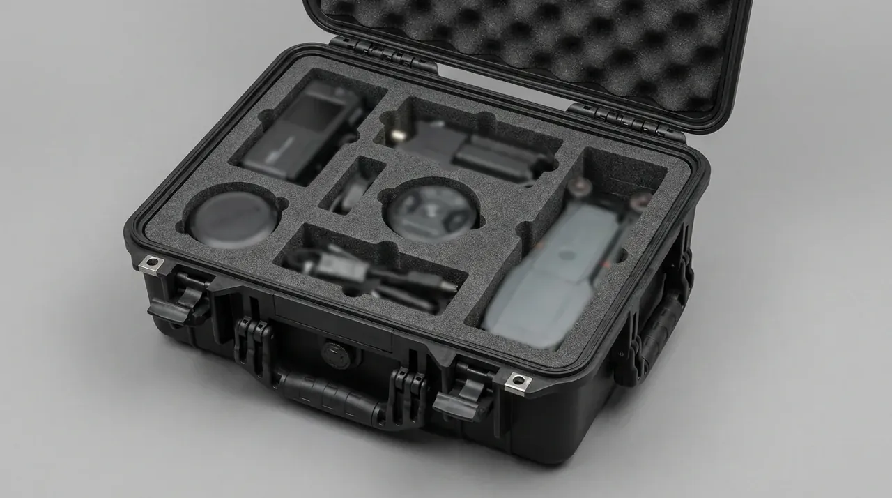
Quick answer: A surgical instrument sterilization storage box of 480×300×130 mm with a 3.0 mm wall and 25% gasket compression holds distortion under 1.2 mm at 121°C and 0.2 MPa, while a three-tier stack tops out at 18 kg.
Table of contents
- Wall thickness and corner radii of the surgical instrument sterilization storage box
- Gasket groove section and compression
- Shell distortion inside the hot pressurized environment
- Three latch positions and lid deflection
- Tray clearance above the base in a three-tier stack
- FAQ
1. Wall thickness and corner radii of the surgical instrument sterilization storage box
The surgical instrument sterilization storage box measures 480×300×130 mm outside and 440×260×95 mm inside, with a 3.0 mm wall, 1.8 kg empty and a 4.5 kg load rating. The base runs 3.0 mm thick, thinning to 2.6 mm up the sides, with the thinnest section at the gasket land just under the rim, measuring 2.2 mm. At 4 mm, uneven cooling warps the base 0.8 mm, ruining rim flatness.
Radii carry the same weight as thickness. Base corners sit at R10, the base-to-side transition at R6, and the rim edge at R3. An R6 transition keeps melt velocity through the corner so no sink forms; at R2 a 0.3 mm hollow appears where the gasket groove lands.
| Area | Wall and radius | What to read |
|---|---|---|
| Base | 3.0 mm | Balance of crush strength and warp |
| Side wall | 2.6 mm | Within 0.5 mm of the base |
| Rim edge | 2.2 mm with R3 | Gasket land, no sink marks |
| Base corners | R10 | Load-bearing radius under stacking |
Mouldings are left 24 h before measuring. A part pulled from the tool sits near 60°C, and rim flatness read then runs 0.4 mm off. Eight units per lot go on a surface plate with a feeler gauge along all four rim edges, held to 0.5 mm.
2. Gasket groove section and compression
The groove sits inside the rim, 5.2 mm wide and 4.0 mm deep, taking a 5×4 mm silicone ring compressed 25% at closure, from 4.0 mm down to 3.0 mm. Below 20% the rim leaks as pressure swings; above 32% the ring flattens, loses rebound, and sticks to the groove wall so it stretches on opening.
The groove is rectangular rather than dovetailed, and demoulding decides it: a dovetail traps the ring but needs a side action the 2.2 mm wall cannot take. The rectangular groove locates the ring on 0.2 mm of width allowance: press the ring in by hand around the perimeter and it should stand 0.8 mm proud of the groove. After 30 min at 121°C and 30 min of cooling, that stand-off may shrink by no more than 0.2 mm.
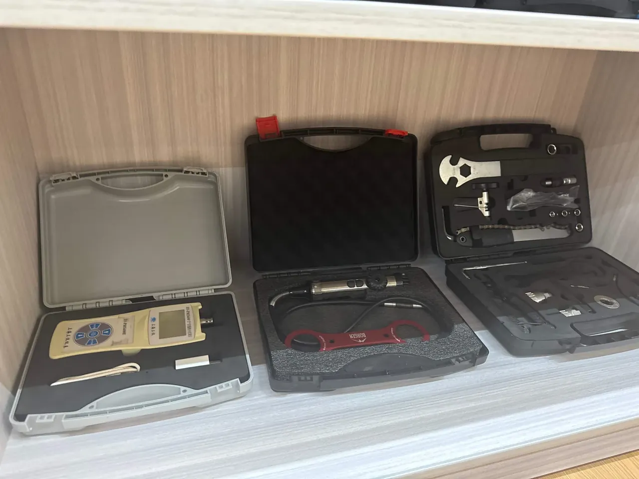
Four 2 mm equalizing holes sit in the groove floor at the edge midpoints. They let trapped air escape as the lid closes; without them the ring lifts on a cushion of air and the compression reading comes out high. Holes are moulded with the groove and deburred, since anything over 0.1 mm of flash cuts into the ring.
3. Shell distortion inside the hot pressurized environment
The box is run at 121°C and 0.2 MPa for 30 min, with heating and cooling each held to at least 12 min. Distortion in the heating phase comes from falling modulus, while the cooling phase releases moulded-in stress, so the two are logged apart: rim spread during heating stays under 0.8 mm, and residual distortion after cooling under 1.2 mm. Merge the two and there is no telling thermal growth from stress recovery.
At 134°C the same box spreads to 1.1 mm and settles at about 1.5 mm of residual distortion. A box headed for 134°C batches needs its rim flatness line relaxed from 0.5 mm to 0.7 mm, or a whole lot gets rejected on a reading that says more about the cycle than the part. Distortion is read with a three-point micrometer at three edge midpoints, taking the largest value.
Tested boxes stay as reference samples. Three hot cycles push residual distortion past 2 mm, which is fatigue rather than a single-pass fault.
4. Three latch positions and lid deflection
Three latches are used: one at the long-edge midpoint and one on each short edge, 260 N each. Three rather than two comes from the 480 mm long edge, which bows outward under 0.2 MPa; with two latches spanning 240 mm, lid deflection at mid-span reaches 1.6 mm and the gasket loses contact there. A third latch cuts the span to 120 mm and brings deflection back under 0.7 mm.
Each catch seat sits in a thickened boss on the side wall, 4.5 mm thick, with a 1.2 mm stainless insert. Force is read per latch at peak with a pull gauge, and the spread across the three may not exceed 40 N; a wider spread means the seats sit at different heights, so one corner of the lid lands while another hangs. After 3000 cycles force may decay 18% before the inserts are replaced.
Latch and hinge carry separate duties: the hinge handles lid rotation, the latch only compresses the gasket. Use a latch as a hinge stop and the seat root cracks within 1500 cycles.
5. Tray clearance above the base in a three-tier stack
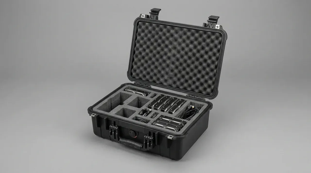
The stack is designed for three tiers, 4.5 kg per box and no more than 18 kg on the bottom unit. The tray sits 8 mm above the base on four ribs, 6 mm wide and 8 mm tall, positioned over the base pads. Under 5 mm the tray touches the base and load runs into the floor middle, sagging 1.5 mm; over 12 mm the tray bounces.
The reading is base sag at the centre, capped at 1.0 mm. At 40°C the reading is 1.4 mm as modulus falls near 60°C, so two tiers suit a hot room.
| Tiers | Total load | Base sag |
|---|---|---|
| Two | 12 kg | ≤0.7 mm |
| Three | 18 kg | ≤1.0 mm |
| Three at 40°C | 18 kg | ≤1.4 mm |
Conclusion
Five figures define the design line of a surgical instrument sterilization storage box: a 3.0 mm base with 2.6 mm sides and an R6 transition, a 5.2 mm groove at 25% compression, 1.2 mm residual distortion at 121°C, three 260 N latches holding lid deflection to 0.7 mm, and 8 mm of tray clearance under an 18 kg three-tier stack. Each belongs to a tool dimension or a rig reading, and changing one forces the next to be recalculated. How instruments are placed or processed inside stays outside this page.
Related Reading
- Choosing a cleaning and disinfection method for case bodies
- Dimension chains and tolerance allocation in case assembly
- Density and rebound of foam for instrument cases
- Converting cavity depth into foam thickness
Related Products
- 8 Series — Gun Cases; Military Equipment Cases; Camera Equipment Cases; Drone Cases; Watch Cases; Knife Cases; First Aid Cases; Electronics Equipment Cases
- WL8-2812 PP Gun Case — model WL8-2812
- All protective cases and toolboxes: 7 series, 158 models