

A water treatment works is a place surrounded by water, chemicals and biological activity all at once. From the screening hall and inlet pumping station to the chemical dosing room and sludge dewatering building, the air carries hydrogen sulphide, sodium hypochlorite vapour, chlorine dioxide and relative humidity that stays above eighty-five percent for most of the year. These conditions attack metal fittings, optical windows and electronic circuit boards far faster than a normal industrial workshop would.
An analyser worth several thousand dollars rarely fails because of the process itself. It fails because transport and storage were unprotected: the optical lens grew mould, the flow cell scaled up, and the terminal block turned green with corrosion. Three years of service can do less damage than three weeks of careless handling.
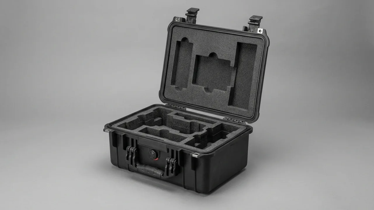
The protection principle behind JUNZHIJIA water treatment instrument cases is that moisture, chemical attack and vibration must each be cut off at a different layer: shell structure, seal chemistry and cavity layout. A case only becomes a real barrier when the material, the gasket compound and the internal partitioning all match the chemical inventory of the plant.
Table of Contents
- The Wet and Corrosive Environment of a Water Treatment Works
- Shell Structure and Material Selection
- Cavity Layout and Fixing for Online Analysers
- Safe Storage and Transport of Reagents and Buffer Solutions
- Protecting Probes, Electrodes and Flow Cells in Transit
- Choosing Between IP65 and IP67 for Washdown, Spray and Immersion
- Chemical Resistance Table for EPDM, FKM and Silicone
- Condensation Control and Pressure Equalisation Valves
- Calibration and Field Verification Workflow
- Transporting Reference Standards and Managing Temperature
- Latches, Hinges and Stacking Load
- Factory Testing and Incoming Acceptance Criteria
- Frequently Asked Questions FAQ
- Conclusion and Related Reading
The Wet and Corrosive Environment of a Water Treatment Works
Treating an entire plant as one generic "damp environment" is the most common starting point for instrument damage. Each process unit imposes a different duty. In the screening hall and inlet pumping station the dominant threat is hydrogen sulphide, generated by sewage under anaerobic conditions. H2S concentrations typically sit between five and fifty parts per million, and can briefly exceed one hundred parts per million during desilting. Dissolved hydrogen sulphide forms a weak acid that selectively attacks copper, silver and nickel plating, which makes terminal blocks and connector pins the first casualties.
The chemical dosing room presents a completely different chemistry. Sodium hypochlorite solution continuously releases chlorine gas and trace chlorate at ambient temperature. The concentration is low but the oxidising power is high, so rubber parts, polyurethane foam and ordinary carbon steel degrade quickly. Around chlorine dioxide generators, hydrochloric acid mist adds a second corrosive agent.
Humidity in a water treatment building stays above eighty-five percent most of the year, and approaches saturation near dewatering centrifuges and thickeners. When a case is heated by direct sunlight during the day and cools rapidly at night, the internal dew point migrates and moisture condenses on the coldest metal surfaces. Condensation does not cause an immediate failure the way immersion does, but within weeks it produces leakage current on circuit boards, fogging on optical windows and drift in reference electrode potential.
Temperature range must also be covered. Outdoor instrument cabinets in northern plants can see minus twenty degrees Celsius in winter, while internal temperatures under direct summer sun can exceed sixty degrees. Silicone gaskets remain elastic at minus twenty degrees while nitrile rubber has already stiffened noticeably, and that difference decides whether the enclosure can hold its IP rating. Selection therefore has to start with a site environment list: dominant corrosive media, peak concentration, relative humidity, temperature limits and whether high pressure washing is used. That list is the input for every structural and material decision that follows.
Shell Structure and Material Selection
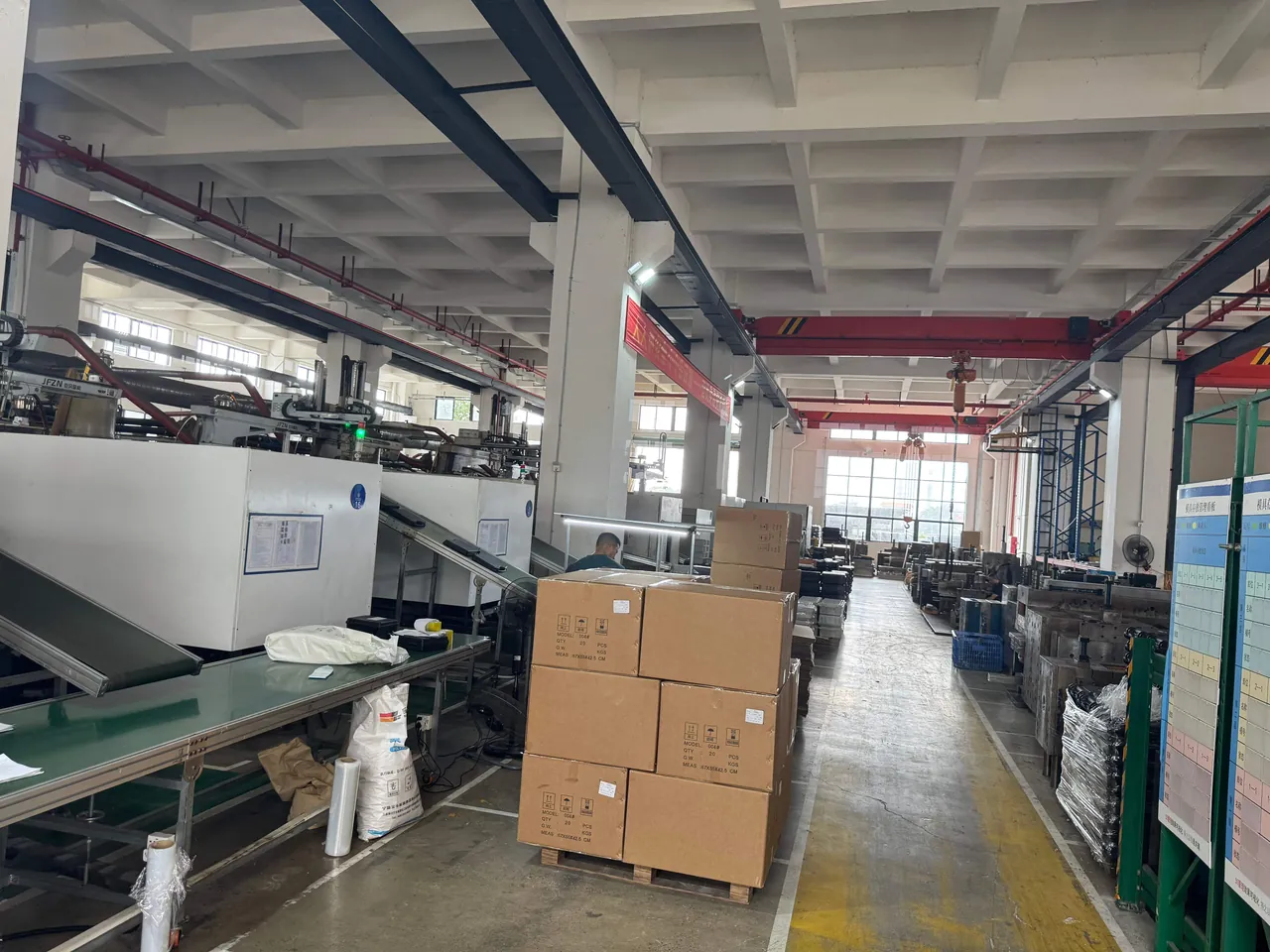
The shell material sets the foundation of protection. Three common enclosure approaches each have a clear boundary of use. Rotomoulded high density polyethylene cases are formed in one piece with no seams and uniform wall thickness, giving excellent impact and chemical resistance, and they suit large multi-item loads. Injection moulded polypropylene or ABS and polycarbonate alloy cases offer tight dimensional tolerance and a smooth surface, which makes panel cut-outs and recessed interfaces easy, and they suit standardised small and medium instruments. Blow moulded cases are the cheapest option but wall thickness is difficult to control, so they are generally limited to low value consumable handling.
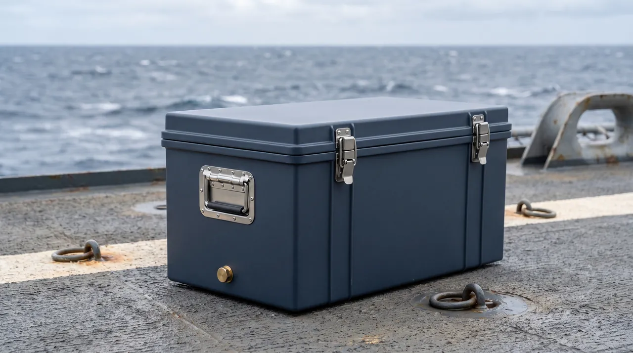
Hardware is the most frequently overlooked corrosion weak point. In chlorine and sulphur bearing atmospheres, ordinary zinc plated steel latches can show red rust within months. Grade 304 stainless steel is the sensible baseline, and grade 316L is worth the upgrade near dosing rooms or on coastal sites. Latch pins should avoid dissimilar metal combinations that create galvanic corrosion, or use nylon bushings to isolate the two metals. Reinforcement ribs on the base and sides should be provided, typically at two to three times the wall thickness in height, to resist creep under stacking load and the point loads of manual handling.
Interior surface treatment matters as much. A polyurethane coating or an EVA liner panel cushions the instrument and breaks the path by which a condensed water film on the shell can reach the equipment. For large cases moved by forklift, moulded pallet slots or wear resistant feet should be provided so the base cannot be worn through, which would destroy the seal.
| Item | Rotomoulded HDPE | Injection PP | ABS + PC alloy |
|---|---|---|---|
| --- | --- | --- | --- |
| Forming method | Rotational, seamless | Injection, tight tolerance | Injection, smooth finish |
| Typical wall thickness | 3.5 to 6 mm | 2.5 to 4 mm | 2.5 to 3.5 mm |
| Sodium hypochlorite resistance | Excellent | Excellent | Good, stress cracks long term |
| Hydrogen sulphide resistance | Excellent | Excellent | Good |
| Impact at minus 20 C | Excellent | Moderate | Moderate to poor |
| Panel cut-out workability | Moderate | Excellent | Excellent |
| Single mould cost | Low | Medium | Medium |
| Best fit | Large mixed loads | Standard instruments | Presentation grade sets |
For cases stored outdoors long term, ultraviolet ageing also demands attention. Polypropylene without light stabilisers chalks and micro-cracks after two years of continuous outdoor exposure in southern regions, and the flatness of the sealing face then degrades. Grades containing hindered amine light stabilisers, combined with a matte textured exterior that reduces light absorption, extend service life considerably.
Cavity Layout and Fixing for Online Analysers
An online analysis system normally consists of a transmitter, sensor probes, a flow cell, reagent bottles and standard solutions, and the sensitivity of these items to vibration and compression varies widely. A sound cavity design splits the system into three physically separated chambers. The instrument chamber holds the transmitter, display unit and junction box. The probe chamber holds pH, ORP, turbidity, residual chlorine and conductivity sensors. The reagent chamber holds buffers, standards and cleaning agents. The first purpose of three-chamber isolation is to stop reagent leakage from contaminating electronics, and the second is to give each item a matching cushion stiffness.
The instrument chamber usually uses EVA foam of thirty to forty-five Shore A, CNC cut to the transmitter outline within plus or minus zero point five millimetres, giving a slight compression fit that neither rattles nor jams. The critical point in the probe chamber is to avoid axial shock. Glass bulb electrodes and sapphire windows fracture easily under axial compression, so probes should lie horizontally along the long axis with ten to fifteen millimetres of cushion margin at each end, located with polypropylene brackets, never lashed by cabling around the body.
The reagent chamber needs secondary containment: a polypropylene tray or dedicated liner that catches leaked liquid with a capacity of at least one hundred and twenty percent of the total reagent volume carried. A chemical resistant polyethylene pad goes on the chamber floor. Partitions separate the three chambers, and no through holes should be left between a partition and the case floor. If cabling must cross, fit a waterproof grommet and seal the inner side with adhesive. This layout adds complexity, but for a field calibration case it is the most direct way to control cross damage.
Safe Storage and Transport of Reagents and Buffer Solutions
Most reagents used in water treatment analysis and calibration are corrosive or oxidising, including pH 4.00, 6.86 and 9.18 buffers, ORP standard solution, residual chlorine standards, and dilute hydrochloric acid, sulphuric acid and sodium hydroxide cleaning solutions. Their common features are small bottle volume, a body that rolls easily and a screw cap, which together allow slow leakage under transport vibration. Diluted acid can corrode adjacent instrument nameplates and metal brackets within days.
Storage and transport design should proceed in the order of restrain, seal, then absorb. For restraint, CNC cut EVA or IXPE holes matched to the bottle outside diameter, with a clearance of zero point five to one millimetre and a depth of at least two thirds of bottle height. Bottles above one hundred millilitres also need a top retaining bar. For sealing, wrap the bottle thread with a layer of PTFE tape before packing, and place oxidising standards inside individual self sealing bags.
For absorption, lay a two to three millimetre layer of acid resistant absorbent mat or superabsorbent sheet on the chamber floor, sized to the largest single bottle volume. Residual chlorine standards and enzyme substrates that need cold chain transport should have a separate exchangeable cold pack compartment, with foam between the pack and the bottles to prevent local freezing on direct contact. The exterior should carry compliant corrosive goods labelling positioned clear of latches and handles so that handling does not wear it away.
Protecting Probes, Electrodes and Flow Cells in Transit
Probes are the highest value and most frequently failed items in an online analysis system, and they deserve dedicated protection structures. The sensitive bulb of a pH glass electrode has a wall thickness below zero point three millimetres, so a single direct impact can create micro-cracks that show up as slow response and reduced slope while the exterior looks perfectly normal. The liquid junction of a reference electrode is a porous ceramic or PTFE ring, and blockage by dried potassium chloride crystals produces a high impedance fault. Turbidity transmitter and receiver windows are optical glass, and surface scratches cause a persistent low reading bias. Conductivity sensors are mechanically robust, but friction on the platinum black coating shifts the cell constant.
Against these characteristics, the probe chamber should follow three rules: dedicated location, soft contact and no stacking. Dedicated location means every probe has its own cradle, with a clearance of no more than zero point five millimetres against the probe body and a cradle length covering the main body rather than the head, so that loads land on the strongest section. Soft contact means the cradle wall carries a two millimetre closed cell PE or EVA layer, ideally twenty-five to thirty-five Shore A, which absorbs shock without creating excessive insertion force.
No stacking means probes must never sit one above another in the same chamber. They should lie side by side or on separate trays, and tray supports should prevent upper trays transferring load onto lower probes. Flow cells and cuvettes should be removed and packed separately, and the seals and lenses inside a flow cell should be taken out before transport, wrapped in clean soft cloth and placed in a dedicated compartment. For probes stored long term, fill the protective cap with three point five molar potassium chloride solution and fix a clear keep wet label inside the lid.
Choosing Between IP65 and IP67 for Washdown, Spray and Immersion
IP ratings are defined by IEC 60529 and the equivalent national standard GB/T 4208. The first characteristic digit covers solid particle ingress and the second covers water. In water treatment applications the three ratings most often discussed are IP65, IP66 and IP67. IP65 means protection against water jets, tested with a six point three millimetre nozzle at twelve point five litres per minute from about three metres for at least three minutes. IP66 means protection against powerful water jets, tested with a twelve point five millimetre nozzle at one hundred litres per minute from about three metres for at least three minutes. IP67 means protection against temporary immersion, with the case submerged one metre below the surface for thirty minutes with no water ingress.
The central selection error is to treat washing as if it were immersion. Maintenance hosing in a water treatment plant is usually a low pressure hose with an impact pressure under zero point three megapascals, which sits in the IP65 to IP66 range. But if the case is stored below the washing point, if the floor is frequently flooded, or if the case has to be set down near a sump, the real duty has already crossed into IP67 territory. The more reliable test is whether, at any point in its life, the base of the case could be under water. If the answer is yes, specify IP67 rather than IP65.
An IP rating also describes a new unit, not long term durability. Gasket compression set, scratches from grit and latch pressure decay can reduce a certified IP67 case to something near IP54 after a year. Treat the rating as a design ceiling and maintain it through scheduled gasket replacement.
| Site condition | Suggested rating | Main risk | Gasket inspection interval |
|---|---|---|---|
| --- | --- | --- | --- |
| Indoor instrument room, no hosing | IP54 to IP65 | Dust, occasional drips | 24 months |
| Dosing room, low pressure hose | IP65 | Chemical splash, damp | 18 months |
| Dewatering building with wet floor | IP66 to IP67 | Pressure wash, brief immersion | 12 months |
| Outdoor tank side, rain and splash | IP67 | Storm, condensation, UV | 12 months |
| Temporary storage beside a sump | IP67 | Full immersion risk | 12 months |
Chemical Resistance Table for EPDM, FKM and Silicone
The gasket is the only part of a protective case that repeatedly contacts the chemical medium directly, and choosing the wrong compound defeats even the thickest wall. The three elastomers common in water treatment each have clear strengths and limits. EPDM performs strongly in polar and oxidising media and resists sodium hypochlorite, ozone, ketones and hot water well, but swells rapidly in mineral oils, petrol and aromatic hydrocarbons. FKM offers excellent oil, solvent and high temperature resistance and is stable against mineral acids and most organic solvents, but is sensitive to strong bases, ketones and some chlorinated media, and its low temperature performance is comparatively weak. Silicone has the widest temperature range, from minus fifty to two hundred degrees Celsius, with outstanding ozone resistance, but low mechanical strength and poor oil resistance.
The table below rates the three compounds against twelve media commonly found in water treatment plants, on the basis of continuous contact at ambient temperature. A means suitable for long term use, B means suitable for short term contact, and C means not recommended. The figures are general engineering guidance, and any specific project should still confirm against the supplier compatibility data sheet and an actual immersion test.
| Medium | EPDM | FKM | Silicone |
|---|---|---|---|
| --- | --- | --- | --- |
| Sodium hypochlorite 12% | A | B | B |
| Chlorine dioxide solution | A | C | B |
| Hydrochloric acid 10% | A | A | B |
| Sulphuric acid 30% | A | A | C |
| Sodium hydroxide 30% | A | C | C |
| Hydrogen sulphide, wet | A | B | B |
| Polyaluminium chloride solution | A | A | A |
| Polyacrylamide solution | A | A | A |
| Ozone, gas phase | A | B | A |
| Methanol | A | A | B |
| Diesel and lubricating oil | C | A | C |
| Hot water at 80 C | A | A | A |
The table shows that EPDM is the most dependable general choice for a water treatment plant, because it covers the four high frequency media of sodium hypochlorite, wet hydrogen sulphide, polyaluminium chloride and hot water at the same time. FKM should only be considered where oils, solvents or high temperature dominate. Silicone is better as a supplementary option for cold outdoor duty. It is worth stressing that gasket failure often comes from a mixed medium rather than a single one. A dosing room may contain both hypochlorite vapour and acidic cleaning agent, and the mixture forming near the sealing face can behave quite differently from either substance alone. In such duty, run an immersion test with the actual site chemical, holding samples at ambient and forty degrees Celsius for seventy-two hours and measuring volume change and hardness change before deciding.
Condensation Control and Pressure Equalisation Valves
Condensation is the most underrated failure path in water treatment instrument protection. When a case is heated to fifty degrees Celsius by the sun and cools to fifteen degrees at night, the moisture difference between saturated internal air at the two temperatures can exceed ten grams per cubic metre. That moisture condenses on the coldest internal surface, which is usually a metal transmitter housing, an optical lens or a stainless steel screw.
The most direct countermeasure is a pressure equalisation valve. A valve fitted with an ePTFE membrane lets air pass freely to equalise internal and external pressure while the microporous structure blocks liquid water and dust. In water treatment duty, hosing, sun exposure and handling all generate pressure differentials within tens of kilopascals. Without an equalisation valve, the gasket is repeatedly compressed and sucked, which accelerates compression set. When specifying a valve, check air flow rate, cracking pressure, membrane chemical resistance and ingress protection rating, and confirm that the installed position avoids direct spray and standing water.
Two further measures support the valve. First, control the internal moisture source by dehumidifying instrument surfaces before packing, so that rain droplets and wiped residual water are not sealed inside. Second, fit replaceable desiccant packs at roughly one gram of silica gel per litre of internal net volume, with a humidity indicator card outside the case so packs are changed at the colour threshold. For sensitive turbidity analysers, a small regenerative drying module can be fitted inside. Desiccant cannot replace the equalisation valve, because it only absorbs moisture already inside. See Pressure Equalization Valve for the structural design approach.
Calibration and Field Verification Workflow
A protective case does more than protect in transit; it often doubles as the working platform for field calibration, so the internal layout has to support the operation. A complete field verification workflow covers visual inspection of the electrode and its protective solution, confirmation of standard solution temperature and expiry, execution of zero and slope calibration, recording of pre and post calibration potential values, and entry of results into the verification record for comparison with the previous entry.
The case should support a take it out and use it sequence, with reagent bottles, beaker holders, waste collection cups and wiping consumables arranged front to back in the order of use, so that the technician does not have to search during calibration. A removable polypropylene work plate inside the case, with a three to five millimetre raised lip, contains spilled standard solution and keeps it out of the main chamber. The waste cup should have a dedicated cradle and a marked maximum level, and should be removed and emptied as a unit after calibration so that liquid residence time inside the case is minimised.
Data traceability matters as much as the procedure. A waterproof calibration card fixed inside the lid should list the batch number, preparation date, expiry date and acceptable slope range for the standard solutions in use. For a pH electrode, a slope below ninety percent or above one hundred and five percent should trigger maintenance or replacement. Verification frequency follows process criticality, from weekly at drinking water outlets to monthly at process control points. Keeping calibration tools, standard solutions and record cards together in one protective case significantly reduces wasted verification caused by missing tools or expired standards. For general requirements on transporting standards, see Laboratory Sample Transport.
Transporting Reference Standards and Managing Temperature
pH buffers, ORP standards and residual chlorine standards are all sensitive to temperature and light. Buffers change pH through carbon dioxide uptake and microbial growth at high temperature, residual chlorine standards photodegrade under light, and some organic standards separate into layers after freezing. The journey from the plant laboratory to the field measurement point is therefore a genuine test of a case temperature control capability.
The basic approach to temperature management is to define an acceptable range and to monitor it inside the case. Most buffers are recommended for storage between fifteen and twenty-five degrees Celsius, with short term transport relaxed to five to thirty-five degrees. Residual chlorine standards should be kept out of light and refrigerated between two and eight degrees throughout. In the case design, a removable cold pack or phase change material module can provide passive temperature control for the reagent chamber, with a phase change temperature chosen around six to eight degrees so that the internal temperature stays stable for four to six hours in summer. A single use temperature recording label inside the case documents the whole transport profile and becomes part of the data traceability file.
Transport vibration introduces a second risk: sloshing accelerates contact between the standard and air. Filling bottles to the neck to minimise headspace reduces this effect. On arrival, allow at least two hours at room temperature before use so that the standard approaches the sample temperature and temperature compensation error is avoided. For standards shipped between provinces, an external temperature sensitive label should be applied so that a colour change triggers rejection of the batch. For corrosion test methods, see Salt Spray Corrosion Testing.
Latches, Hinges and Stacking Load
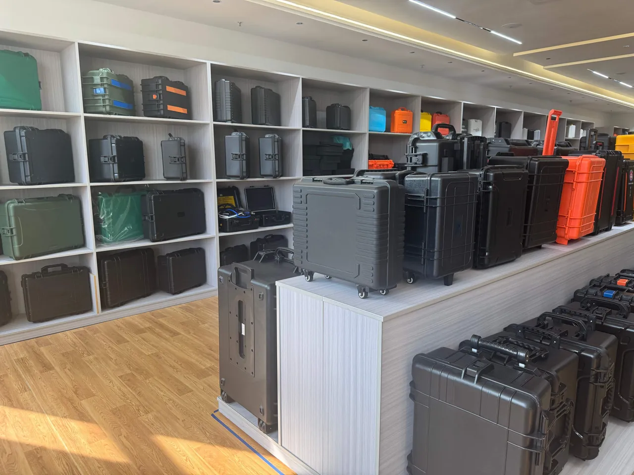
Handling frequency is high in water treatment plants and operators vary, so latch and hinge reliability determines whether the sealing face stays flat over time. Latches should be cam or draw types with a self locking anti-release feature so they do not pop open under vibration. Opening force should sit between twenty and fifty newtons; too light and the latch releases, too heavy and field staff pry it with a tool. Metal hinges carry more load than plastic, but the stress concentration where the pin meets the shell must be distributed by reinforcement ribs. For long service, latches should be cycled ten thousand times and hinges five thousand times with an axial load. Further detail is available in Case Hinge Design.
Stacking load is a hard requirement for storage and transport. Cases holding online analysers are often stacked two or three high in a finished goods warehouse, and long term static load causes creep. If the base and reinforcement ribs are insufficient, stacking pressure transfers to the sealing face and causes permanent deformation. Design should set the stacking test load at three times the fully loaded weight of a single case, hold it for seventy two hours at forty degrees Celsius, and require residual height deformation after unloading to stay within one percent of original height. The lid top should carry locating recesses matching the base profile so that a case cannot slide sideways off a misaligned stack.
Factory Testing and Incoming Acceptance Criteria
The protective capability of a case has to be demonstrated by test rather than judged from the appearance of a sample. For water treatment instrument cases, factory testing is best divided into four groups: sealing, mechanical strength, environmental endurance and chemical compatibility. Sealing tests use the pressure decay method or a flow method. Charge the case to two kilopascals positive pressure, stabilise, and record the decay over thirty seconds; a drop of no more than ten percent of the initial value passes.
Mechanical strength testing covers drop, vibration and stacking. Drop testing sets the height by loaded weight class, and the case is dropped once on a corner, once on an edge and once on a face; afterwards the shell must not crack and internal instruments must not shift. Vibration testing applies a road transport spectrum, and latches and hinges are rechecked for looseness. Environmental endurance covers high temperature and humidity, low temperature brittleness and salt spray. Salt spray runs for two hundred and forty to four hundred and eighty hours, and red rust on metal parts must not exceed five percent of area.
On receipt, open a sample according to the sampling plan and check four things: whether the sealing face shows flash, scratches or mould mismatch; whether the gasket material marking matches the order, with an immersion comparison from a cut section where necessary; whether the pressure equalisation valve is clear, checked by lightly touching the membrane for adhesion; and whether hardware material matches the contract. Any nonconformity should be logged with photographs. Where sealing problems recur within one batch, hold receipt and require sealing test data for the whole batch.
Frequently Asked Questions FAQ
Q: Why can an ordinary plastic tool box not replace a proper instrument case in a water treatment plant?
A: An ordinary plastic tool box typically seals only against dust and light splashes, which corresponds to roughly IP54, and its liner is usually plain PE foam with no chemical resistance claim. The air in a water treatment building carries sodium hypochlorite vapour and wet hydrogen sulphide for long periods, and ordinary polypropylene liner material embrittles slowly in oxidising media, shedding powder that contaminates optical windows within months. If the seal is nitrile rubber, contact with sodium hypochlorite can swell it by more than twenty percent in volume, rapidly destroying compression. More importantly, a plain box has no pressure equalisation valve, so when hosing cools the shell a negative pressure forms inside and draws chemical laden water along the sealing face into the case. JUNZHIJIA cases for water treatment duty use a one piece shell, EPDM gaskets and a partitioned liner, and upgrade the hardware material. These changes are precisely what a general purpose tote box does not have. The short term saving is real, but one destroyed electrode or one corroded circuit board usually costs more than the case itself.
Q: Should pH and ORP electrodes be stored wet or dry inside the case?
A: They must be stored wet, and with the correct protective solution. The glass bulb of a pH electrode depends on a hydrated gel layer, and if the electrode dries out that layer contracts. After re-immersion the electrode needs hours or even days to stabilise, and some electrodes permanently lose slope. The liquid junction of a reference electrode will precipitate potassium chloride crystals in a dry environment and block the porous ceramic, which shows up as increased impedance and an unstable reading. The correct practice is to fill the protective cap with three point five molar potassium chloride solution so that the bulb and junction are covered, and to ensure no air bubble sits between cap and electrode. ORP electrodes are also best stored in potassium chloride solution rather than distilled or deionised water, because pure water dilutes the internal reference electrolyte and worsens junction potential drift. Before packing, check that the cap is tight so that solution cannot leak and contaminate other components, and label the inside of the lid so that field staff do not drain the solution and store the electrode dry.
Q: Can an IP65 case be washed with a hose in a dosing room?
A: Yes, provided three conditions are met at the same time. First, washing must use a low pressure hose rather than a pressure washer, with nozzle outlet pressure kept below zero point three megapascals and the nozzle at least one metre from the sealing face. The IP65 test condition is a six point three millimetre nozzle at twelve point five litres per minute, and exceeding that intensity already moves the duty into the IP66 range. Second, the spray direction should not aim directly at the sealing face, the latch gaps or the membrane of the pressure equalisation valve, since angled washing greatly reduces the chance of ingress. Third, after washing, wipe the case dry and check the sealing face for standing water, particularly in the recesses near latch compression points. Where washing is frequent and the floor floods regularly, or where the case has to stand on the floor, specify IP67 to eliminate the immersion risk by design. It is also worth remembering that an IP rating describes a new unit; after a year the gasket develops compression set, actual protection drops, and scheduled replacement becomes essential.
Q: What happens if different chemicals share one chamber?
A: The consequences are usually worse than a single chemical, through three mechanisms. The first is exothermic mixing: acidic cleaning agents and sodium hypochlorite release chlorine and heat when combined, so if both leak and are absorbed by the same pad, the absorbent layer can warm and accelerate ageing of surrounding materials. The second is synergistic corrosion: an acidic film formed near the sealing face by hydrochloric acid mist and wet hydrogen sulphide corrodes stainless steel faster than either medium alone and encourages pitting. The third is cross contamination: vapour from a leaked reagent adsorbs onto the terminal block of an adjacent instrument, creating a persistent damp electrolyte film that lowers insulation resistance. The reagent chamber should therefore be subdivided again, keeping oxidising, acidic and alkaline reagents apart with independent absorbent material for each. Where a shared chamber cannot be avoided, at least separate them with a polypropylene partition and label the contents so that field staff can verify the arrangement quickly.
Q: How often should the desiccant inside a protective case be replaced?
A: The interval cannot be set by calendar alone; it should follow the humidity indicator card and the weight gain of the pack. Silica gel is usually sized at about one gram per litre of internal net volume, and with a well sealed case fitted with a pressure equalisation valve a pack typically lasts two to three months at ambient temperature. Under frequent washing or large day and night temperature swings it may saturate in two to three weeks. The simplest check is the humidity indicator card: most cards change colour at a relative humidity threshold of forty to fifty percent, so a shift from blue to pink means replacement is due. A more precise method is to weigh the desiccant and replace it when the gain exceeds ten to fifteen percent of the original weight. The pack should sit in a breathable non woven bag away from optical lenses so that dust cannot contaminate them. Regeneration requires baking at the specified temperature to constant weight, and after more than five regeneration cycles the adsorption capacity drops noticeably, so replacement is preferable. Remember that desiccant only manages moisture already inside the case and cannot replace the equalisation valve.
Q: Why does an online turbidity analyser sometimes read low after a period inside the case?
A: A low reading is usually not an instrument fault but contamination or fogging of the optical windows. A turbidity analyser converts scattered light intensity into turbidity, so a thin water film, dust layer or foam particle shed from the liner on either the emitter or the receiver window alters the light path and produces a negative bias, typically more than five percent of full scale. There are three main sources of contamination. The first is fog formed by condensation on the windows. The second is powder shed by an ordinary foam liner as it ages in damp conditions. The third is a deposited film from reagent vapour. The corresponding countermeasures are to fit a pressure equalisation valve and desiccant to control condensation, to replace ordinary PE foam with closed cell EVA or IXPE material and add a non woven separator between liner and optics, and to keep the reagent chamber strictly separate from the probe chamber. Before each use, wipe the windows gently with lens tissue and deionised water; do not rub with a dry cloth, which generates static that attracts more dust. If the reading stays low after wiping, check the standard plate and recalibrate rather than adjusting transmitter parameters.
Q: After a case has been dropped in transit, can it still be used?
A: It cannot be judged by appearance, and a full recheck is required before a decision. Start with the exterior: look for through cracks, deformation of the sealing face, and looseness or misalignment of latches and hinges. Any abnormality means the case should be taken out of service and repaired. Next check the interior: remove the instrument and probes and confirm that the transmitter mounting has not shifted, the electrode is not damaged, and the glass bulb and optical windows show no hidden damage. The third step is to retest sealing, using either the pressure decay method or a simple spray test. Apply two kilopascals of positive pressure, record the decay over thirty seconds, and if the drop exceeds ten percent of the initial value the seal has failed and the gasket or the whole case must be replaced. Finally inspect the liner, since EVA or IXPE can compact locally after impact and lose roughly thirty percent of its cushioning in that area, so a visible compression mark calls for local replacement. If all four checks pass, the case can return to service, but the drop should be noted in the maintenance record so it can be linked to any later fault.
Q: Can JUNZHIJIA customise gasket material and liner structure to a site chemical inventory?
A: Yes, and this is one of the most common custom requirements in water treatment projects. The process usually begins with the media list: the customer provides the names, concentrations, contact mode and temperature of the chemicals present, and JUNZHIJIA screens gasket compounds accordingly and verifies the candidates by immersion. Where necessary the actual site chemical is used to immerse samples at ambient and forty degrees Celsius for seventy-two hours, measuring volume change, hardness change and tensile strength retention. The liner structure stage requires a device list and outline dimensions, from which engineers divide the instrument chamber, probe chamber and reagent chamber and produce a CNC cut EVA or IXPE liner prototype. For complete systems used for field calibration, a removable work plate, secondary containment tray and cold pack compartment can be added. The whole customisation process supports OEM and ODM models, and the path from liner drawing approval through sample case fitting to volume delivery normally includes a sample verification step, so the customer can carry out a real installation and transport test before releasing mass production.
Conclusion and Related Reading
Water treatment instrument protection means turning moisture, chemical attack and vibration into measurable engineering parameters, then matching shell material, gasket chemistry and cavity layout to each one.
Related Reading