

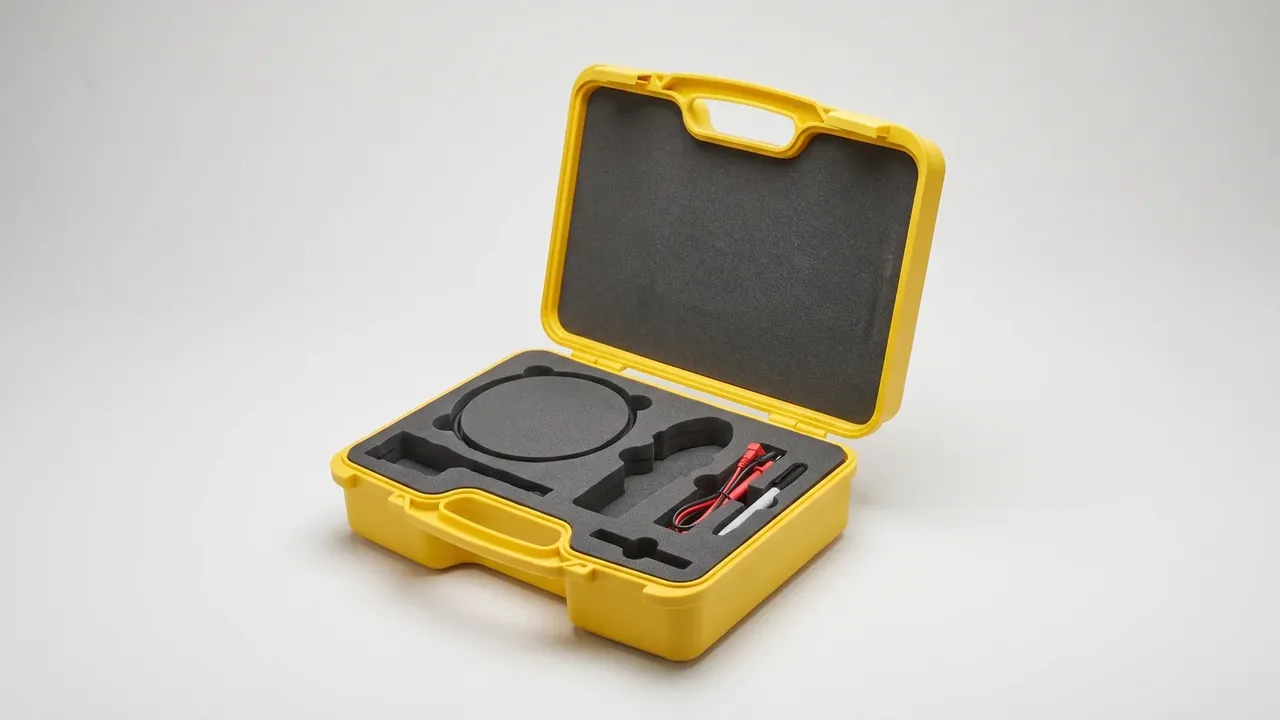
Quick answer: Weld lines on injection cases cost most at a radius or a boss root: a 90° meeting angle keeps 62 % of tensile strength, 135° brings back 78 %.
Table of contents
- How a Weld Line Forms
- Strength Retention: Position Sets the Loss
- Melt, Mould and Injection Speed
- Design Rules and Inspection
- FAQ
1. How a Weld Line Forms
Any core, insert or slide splits the melt. The fronts run around the obstacle and meet again downstream with a skin 15–30 ℃ colder than the bulk, and the chains across that interface never entangle. What comes out is a visible hairline, and where it lands is decided by the gate, not the operator.
The angle sets the shape. At 90° the fronts collide head-on and the gas between them has nowhere to go, so the interface is weakest. At 150° they merge almost in parallel and the shear scrapes the cold layer thin. A section at 50× reads a V-notch 0.04 mm deep at 90° and 0.012 mm at 150°.
Temperature decides how much skin there is. Melt at 240 ℃ leaves the gate and reaches the mid-side of a long case at 215 ℃, so the fronts meet as partly frozen material.
Counting the lines reverse-engineers the tool. Weld lines on injection cases follow the gate layout: one gate with a central core leaves one main seam, two opposed gates leave two parallel lines at the mid-sides, four bosses add four short ones.
2. Strength Retention: Position Sets the Loss
Weld lines are graded against unseamed bars from the same tool and lot: five bars per group at 50 mm/min. A flat mid-panel holds 78 % of tensile strength, while the same seam on an R5 radius drops to 64 %. The weld is not what changes — the stress state is. A radius already carries bending, and the V-notch sits on a loaded section, lifting the concentration factor from 1.6 to 2.4 and cutting the crack threshold by 30 %.
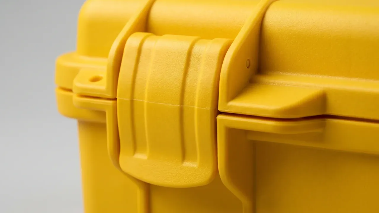
Wall thickness is the lever people miss. Going from 2.5 mm to 3 mm takes the notch from 0.05 mm to 0.035 mm and adds 4 points, because a thicker wall cools slower and lets the chains diffuse across the interface. Case bodies should carry that margin instead of sitting at the 2.2 mm floor to save compound.
A boss root is the worst case. The melt wraps the column and closes 2–3 mm from it, where the wall steps from 3 mm to 6 mm and fastener load arrives; in a 1.2 m six-face drop, cracks at weld lines on boss roots appear four times as often as on flat panels.
| Weld line position | Tensile retention | Stress concentration | Cracks after 1.2 m drop |
|---|---|---|---|
| Mid-panel | 78 % | 1.6 | 8 % |
| Radius R5 | 64 % | 2.4 | 31 % |
| Boss root | 61 % | 2.6 | 34 % |
| Rib intersection | 58 % | 2.8 | 37 % |
3. Melt, Mould and Injection Speed
Melt temperature is the first dial that shifts weld lines. ABS runs 220–250 ℃ and PP 210–240 ℃; every 10 ℃ adds about 3 points because the interface gets more diffusion time. The ceiling is real: ABS above 260 ℃ degrades, odour and silver streaks come first, and strength falls away.
Mould temperature sets the skin. At 40 ℃ the interface skin measures 0.06 mm, at 60 ℃ it is 0.03 mm, worth 8 points. Conformal cooling is easy on a case tool; holding the halves within 5 ℃ is not, and a colder half pulls the meeting point 15 mm off position.
Injection speed cuts both ways. Between 30 and 60 mm/s every 10 mm/s lifts the front by 3–5 ℃ and adds 2 points; past 80 mm/s the flow traps gas, scorch appears at the seam, porosity climbs from 0.5 % to 2 %, and strength collapses.
Venting is the step people skip. A 0.02 mm deep, 10 mm wide vent at the cavity end gives the gas a route out, removes scorch and adds 3 points; a blocked vent leaves a blackened seam over a 0.2 mm porosity band that no temperature change repairs.
| Parameter | Normal | Raising it | Limit |
|---|---|---|---|
| Melt temperature | 230 ℃ | +3 points per 10 ℃ | 260 ℃ degradation |
| Mould temperature | 55 ℃ | 8 points over 40 ℃ | halves within 5 ℃ |
| Injection speed | 45 mm/s | +3–5 ℃ at the front per 10 mm/s | 80 mm/s gas traps |
| Vent depth | 0.02 mm | removes scorch | blocked by flash |
4. Design Rules and Inspection
Three rules move the seam without fighting the process. Split the flow symmetrically so the meeting point lands on a non-load-bearing long side. Put an overflow well 0.8 mm deep about 10 mm upstream and trim it after moulding, so cold material and gas leave the part. Chamfer a boss root at R0.5 and taper the wall from 6 mm to 3 mm, which walks the seam off the column.
Radii under R5 are a no-go zone for weld lines: the corner already raises stress, and a seam across it turns a 1.2 m drop into a guaranteed crack, so either move the gate or add a 2 mm guard rib and let the seam close behind it.
Inspection runs in three steps. Sight the part under 200 lux side light and mark any continuous hairline. Wipe dye penetrant after 5 min, when the notch keeps the red and anything deeper than 0.03 mm fails. Drop 1.2 m on six faces, section through the seam, and look for a white interface that says the layers have opened.
Write the rule into the acceptance document: a weld line on a radius or a boss root fails on position alone, whatever the tensile result says, while a flat-panel seam above 75 % retention passes with its location marked. Run the decay test alongside, 0.3 kPa held 60 s with no more than 0.5 kPa lost after the drop.
Sampling takes 5 parts per 500 for destructive checks: a 50× photo of the section, the notch depth, and the position against the first article. Drift beyond 10 mm points at the water circuit, a deeper notch at melt temperature or speed, and both are settled in the shop rather than at the drop rig.
Conclusion
Weld lines are interfaces every injection case carries, and position decides more than depth: the same 78 % retention is a cosmetic line on a flat panel and a crack starter on a radius or a boss root. The process can lift retention from 62 % to 78 %, the design can walk the seam off the load path, and only both together let a body pass a 0.3 kPa decay test after six 1.2 m drops.
This article discusses only the container (case body) side of specifications and design intent, and does not cover any handling, loading or use of the contents.
Related Reading
- How an injection-moulded protective case body is built
- PP against ABS for case bodies: where each one wins
- Mould care and cavity maintenance between runs
Related Products
- 8 Series — Gun Cases; Military Equipment Cases; Camera Equipment Cases; Drone Cases; Watch Cases; Knife Cases; First Aid Cases; Electronics Equipment Cases
- WL8-2812 PP Gun Case — model WL8-2812
- All protective cases and toolboxes: 7 series, 158 models