

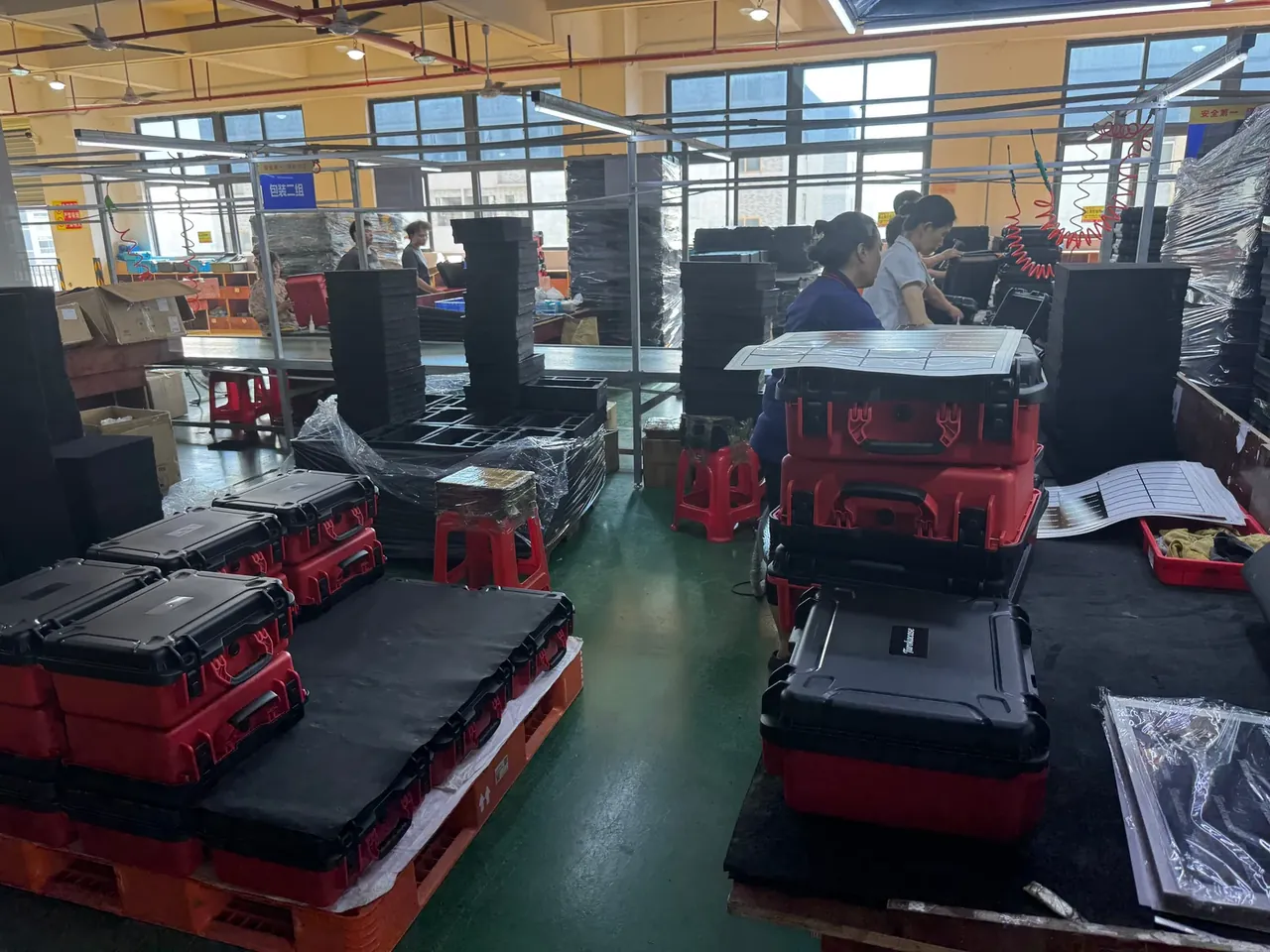
Quick answer: The Wireless signal tester shockproof hard box lifts a 2.4 kg unit to a 38 Hz natural frequency and keeps transmissibility under 0.6 after a 30 min sweep.
Table of contents
- Wireless signal tester shockproof hard box: what damping must achieve
- Thickness ratio in the EVA suspension layer
- Corner posts and natural frequency
- Antenna and connector exit clearances
- Buffer settings for test crews
- FAQ
1. Wireless signal tester shockproof hard box: what damping must achieve
Packing the tester is the easy half; whether the box keeps vibration out depends on the thickness ratio of the suspension layer. The Wireless signal tester shockproof hard box measures 420×330×180 mm outside and 370×280×135 mm inside, weighs 2.4 kg and uses a 4.0 mm wall. Transport energy clusters between 5 Hz and 25 Hz, close to the natural frequency of the shell-plus-liner system, so a poor ratio is amplified three to five times. Hold transmissibility below 0.6 and the unit sees less acceleration than the table; thickness, post size and openings follow that figure.
Transmissibility is response acceleration over input: under 1 counts as isolation.
| Mount setting | EVA thickness | Design compression | Unit mass |
|---|---|---|---|
| Thin layer | 20 mm | 15% | Up to 1.5 kg |
| Middle layer | 25 mm | 20% | 1.5 to 2.5 kg |
| Thick layer | 30 mm | 25% | Above 2.5 kg |
2. Thickness ratio in the EVA suspension layer
EVA for the Wireless signal tester shockproof hard box runs 60 kg/m³ to 100 kg/m³, roughly 25 to 40 on the Shore C scale, the usual insert band. The same hardness at 20 mm and 30 mm gives twice the travel. Thickness is split by unit mass: with a fixed contact area, pressure sets compression, which must land between 15% and 25% of thickness so the foam stays elastic. Past that it densifies and passes vibration straight through.
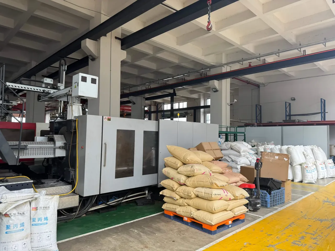
Compression set belongs in the same conversation: held 22 h at 50% compression under ASTM D395, the foam should recover to within 25% permanent set, or repeated open-close cycles will loosen the cavity.
A 30 mm layer is not for every Wireless signal tester shockproof hard box: a light unit on short runs takes 20 mm and frees 10 mm of height for the antenna lead, multimodal freight takes 30 mm. Density is read to ASTM D3575, and one sheet can vary 5 kg/m³, so cavity depth follows the measured value. Die-cut thickness holds ±0.5 mm, cavity position ±0.3 mm.
3. Corner posts and natural frequency
Four φ18 mm posts stand at the corners, each as tall as the suspension layer and set 12 mm in from the inner corner. They do not fill the corner but give it local stiffness, lifting the natural frequency from about 30 Hz to 38 Hz, above the 5 Hz to 25 Hz band where road energy is concentrated.
The sweep runs 5 Hz to 200 Hz at one octave per minute, about 30 min, with accelerometers on table and unit; dividing the curves gives transmissibility. The peak lands at 38 Hz, and its height is the margin.
Posts are cut from 45 kg/m³ EVA roll, held to ±1 mm on diameter, with four heights within 0.5 mm so the unit does not land on one corner first. A ten-minute dwell at 38 Hz shows creep: a drop above 1 mm means a remake.
| Sweep window | Band | What to watch | How it is logged |
|---|---|---|---|
| Early | 5 to 40 Hz | First resonance peak | Peak frequency |
| Middle | 40 to 120 Hz | Post and layer coupling | Peak width |
| Late | 120 to 200 Hz | High-frequency decay | Decay slope |
4. Antenna and connector exit clearances
The antenna exit on the Wireless signal tester shockproof hard box is a φ16 mm bore in the short side wall, its centre 20 mm from the edge, with an R3 break at the rim. It avoids the compression band, and the lead leaves with 15 mm of free length so the unit can settle without tugging the cable. Over the band, every settle loosens the connector.
The connector face points up, and the exit plug uses two steps: the outer presses the O-ring, the inner grips the jacket and fixes the bend point. Both steps are moulded together, coaxial within 0.1 mm; an offset crushes the seal on one side.
IP67 is a benchmark only: the check follows a short immersion and looks for water marks inside the exit. Opening life runs 4000 cycles with two latches at 300 N each, rechecked every 800 cycles.
5. Buffer settings for test crews
The mount setting is the thinnest layer that still holds transmissibility below 0.6 after a thirty-minute sweep, and anything thinner becomes post filler. The line sits on thickness because density can change with a lot while cavity depth cannot once the tool is cut.
Crews match the setting to unit mass: thin for light units, middle for standard ones, thick for multimodal freight. The three share one shell; cavity depth and post height differ, and mixing them wastes the margin.
| Transmissibility reading | Verdict | Action |
|---|---|---|
| 0.45 | Ample margin | Release the batch |
| 0.6 | Borderline | Repeat the sweep once |
| 0.9 | Over the line | Step up one thickness |
Each batch pulls two units for a full re-sweep at 0.5 g table input; a unit responding above 0.3 g goes back for a new layer. The Wireless signal tester shockproof hard box uses a 4.0 mm wall with 5.0 mm corners, and each post sits over that pad, because a thin wall bulges under a loaded post and the preload is gone.
Conclusion
Isolation in the Wireless signal tester shockproof hard box comes from the relationship between layer, post and exit, not from extra shell thickness. The layer sets travel, the post sets natural frequency, the exit sets where the cable bends, and if the three disagree the curve keeps a peak near 38 Hz. A thickness ratio on the drawing beats a sheet of foam added after the fact.
Related Reading
- The Usable-Volume Calculation
- Hard Case and Carton in Transit
- Foam Selection for Instrument Cases
- Reset Sequence After Moving a Balance
Related Products
- 8 Series — Gun Cases; Military Equipment Cases; Camera Equipment Cases; Drone Cases; Watch Cases; Knife Cases; First Aid Cases; Electronics Equipment Cases
- WL8-2812 PP Gun Case — model WL8-2812
- All protective cases and toolboxes: 7 series, 158 models