

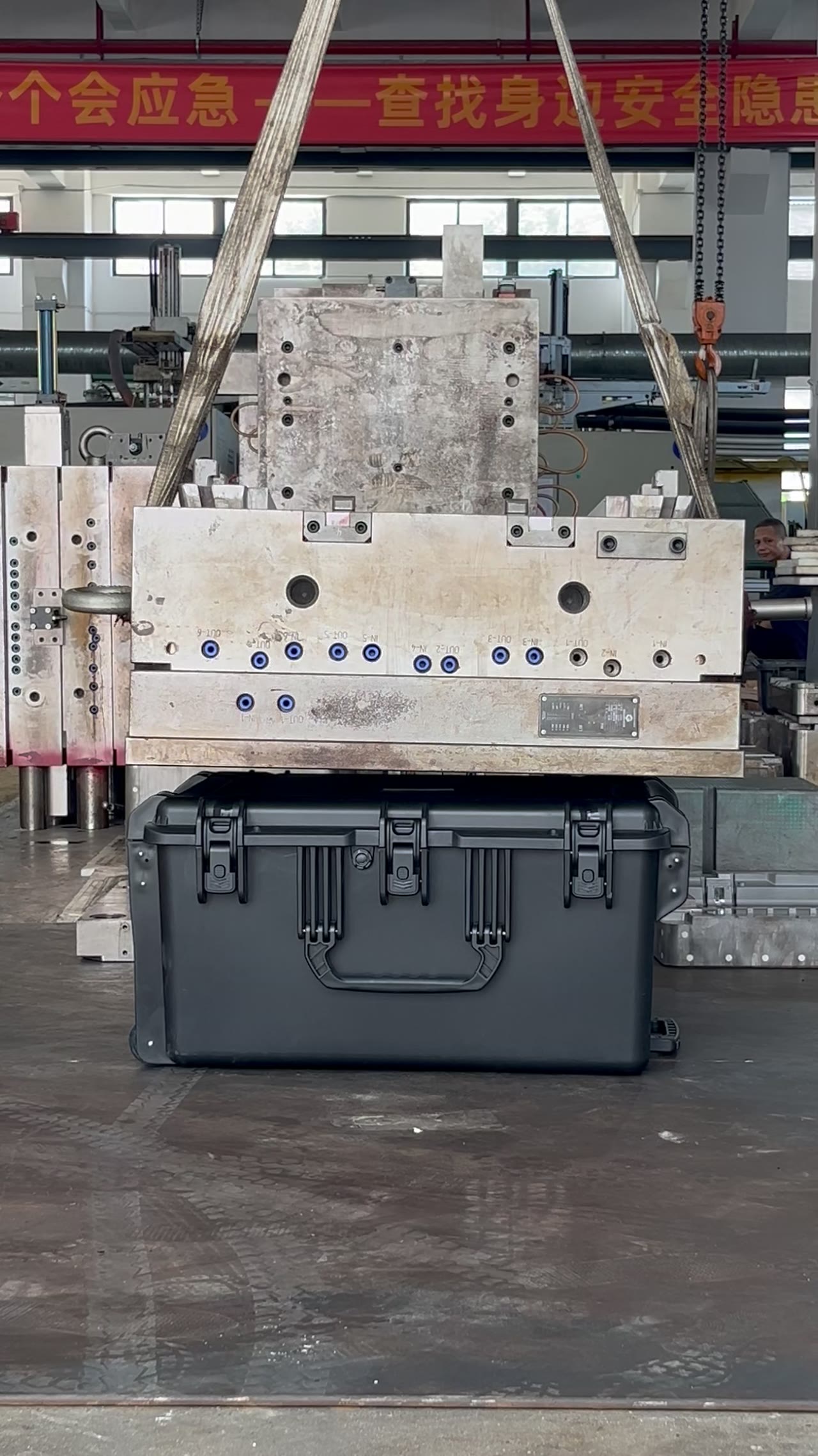
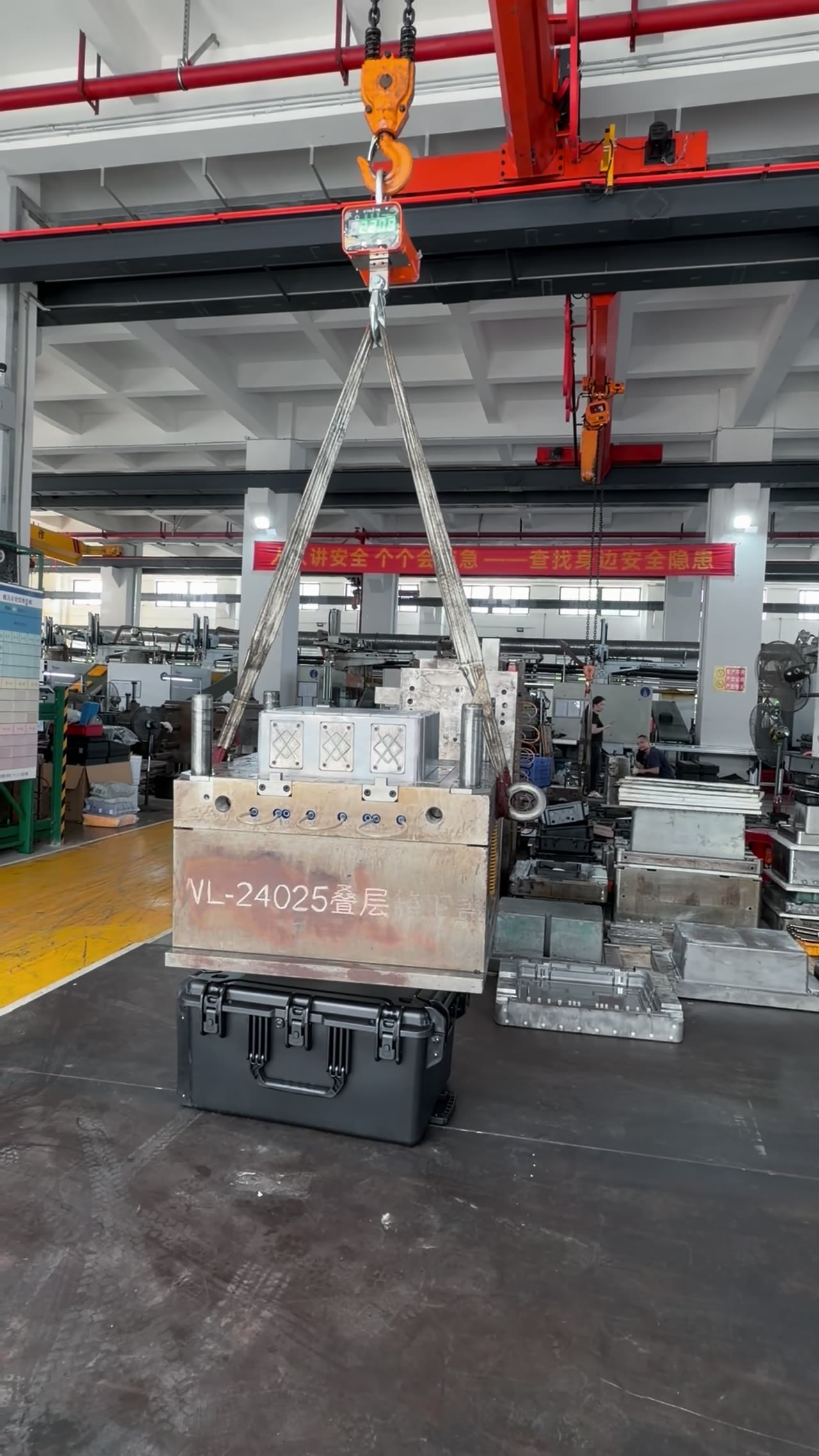

803 Load Challenge: One Model, One Test
One case, one load step, three places to put the indenter, and readings that differ by a factor of three to seven. The clip shows a single run of the three, and it is the run most likely to be mistaken for a statement about strength. What it really shows is the contact patch. Move the indenter from 40 mm to 200 mm across and the pressure beneath it changes twenty-five fold, enough to turn a bent panel into a crushed patch of surface. The rest of this page separates those outcomes.
01The Contact Patch Sets the Number
Load divided by contact area gives pressure, and pressure is what does the work here. Contact edge length ran from 40 mm to 200 mm, a 25-fold spread in area at identical load. The small indenter concentrates stress until material yields directly beneath its edge, leaving a deep mark across a patch the size of a fist. The large one presses the whole panel into a shallow dish instead, and the dial reads higher.
Those are two different failures wearing one label. A deep mark says the surface gave way; a wide sag says the panel bent. Averaging them into a single figure hides the only thing worth knowing. State the indenter size beside every reading, or the reading cannot be compared with anything, including the next run on the same case.
02Face, Edge, Corner: Three Ways to Resist
Three positions went under the indenter: mid-panel, one edge, one corner. Mid-panel behaves as a plate in bending, an edge as two plates folding against each other, a corner as three plates pushing back at once. Peak load at the face centre came out 2.5 to 4.5 times what the corner carried, and deflection at equal load varied 3 to 7 times across the three.
That ratio is not a fixed property of the moulding. Shrink the indenter and the corner looks heroic, because force lands on a small patch and three walls share it. Grow the indenter and the advantage thins as load spreads into the flats. Quote the ratio without the indenter size and it is a number with no premise behind it.
03Where the Mark Lands Beats How Deep It Goes
Wall thickness through the face-centre region measured 2.5 mm to 4.0 mm, and marks ran 0.2 mm to 1.5 mm deep. At the top of that range the indentation approaches 40 percent of wall section. Under a tenth, the surface springs back and keeps only a pale ring; past a third, material beneath the indenter edge has been compacted and stays that way, so a second press at the same spot always reads worse.
Location carries more information than depth. A mark at mid-panel is a by-product of bending and usually harmless. The same depth beside a latch seat, at a rib root, or against a boss sits on ground already carrying concentrated stress, and it lifts that concentration another step. Log coordinates for the mark, not just its depth in millimetres.
04Corner Geometry: Radius First, Ribs Second
Corner radii spanned 6 mm to 20 mm. A radius replaces the hard intersection of three walls with a transition surface, so force crosses from one wall to the next without a sharp turn. Tight radii concentrate stress along that intersection and whiten on the inside first. Generous ones spread load but gather material during moulding, leaving uneven wall and locked-in stress once the part cools.
Three to six ribs usually run one per face with extras between. Their job is not to stiffen the corner in place but to route corner load into the adjacent flats so those areas join the work. Ribs normally stop short of the radius to preserve it, and how far short they stop decides whether any load actually transfers.
05Log the Position Before the Deflection
Order matters on this side of the rig. Write down indenter size, contact position, and load direction first, read the dial second. Press the same point three times and a spread above 1 mm means the indenter is not seated flat or the surface was never level, so set that set aside. Move to a new position and reseat the indenter, because an edge resting on a rib measures the rib.
The footage documents a procedure. Whether a given case suits a given load is settled by the formal record for that batch, and a video is not a load rating. Three habits carry the method: circle each contact point in marker, measure mark depth and log its coordinates after every press, and rerun the whole comparison whenever indenter size changes rather than splicing old numbers onto new ones.
| Face-centre to corner load ratio | 2.5–4.5× |
|---|---|
| Indenter contact edge | 40–200 mm |
| Local indentation depth | 0.2–1.5 mm |
| Corner ribs | 3–6 |
| Corner radius | 6–20 mm |
| Contact positions tested | 3 |
| Sag ratio between contact points | 3–7× |
| Face-centre wall thickness | 2.5–4.0 mm |
FAQ
So how much does the 803 actually carry?
Not as one figure. Face centre against corner differs by 3 to 7 times at equal load, and moving the indenter from 40 mm to 200 mm changes contact pressure 25-fold. A load number means nothing without position, indenter size, and direction attached to it.
Why does the corner read so low?
Three walls meet and share the load there, and the radius plus corner ribs route it outward into the flats. Radii from 6 mm to 20 mm spread it further the larger they get. Overall sink stays small because a corner is close to rigid, though a local mark can still run deeper than at mid-panel.
Is a smaller indenter a harsher test?
It tests something else. A 40 mm contact concentrates pressure and cuts deep local marks, which speaks to surface crush resistance. A 200 mm contact dishes the whole panel, which speaks to stiffness. The two do not convert, so fix one size for a comparison series and rerun if it changes.
Does a 1 mm mark at mid-panel matter?
Against 2.5 mm to 4.0 mm of wall, 1 mm is roughly a third, past the point where the surface springs back. Stiffness of the case is largely unaffected. The same depth beside a latch seat or a rib root is a different question, because that ground was already concentrated.