

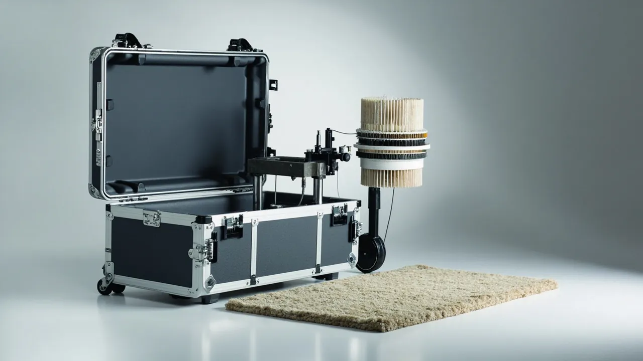
A tufting component case has to settle two conflicting requirements at once: long slender parts hate bending, while matched precision parts hate contact. A needle bar may run several metres, its tufting needles sit at a gauge that converts to only two or three millimetres, and straightness is judged in microns per metre. Give it an unsupported mid-span, or crowd the supports until they pinch, and the bar will bow slowly. A bowed needle bar cannot be straightened back into specification on site, and it will deliver uneven pile height, irregular tuft density and backing damage once the machine runs. Against that, loopers and cut-pile knives are thin-wall precision parts used as matched pairs; a single collision or a patch of rust destroys the pairing and forces replacement in pairs. The centre of gravity of the design is therefore support layout rather than cushion thickness. Use enough supports to hold deflection inside a safe band, isolate matched parts and cutting edges in individual pockets, and finish with an inhibiting atmosphere, desiccant and a barrier bag to control corrosion.
The structural pain points in carpet manufacturing cluster tightly. Equipment is dominated by long parts, which makes transport and lifting difficult. Some needle bars and jacquard assemblies carry high unit value and long lead times, so damage means waiting for a factory production slot. Meanwhile loopers, cut-pile knives and yarn tubes are small, numerous and finely graded, and mixed packing drives counting and pairing labour through the roof. Separating the packaging system for long parts from the system for small parts, and building a case-to-part-to-machine-position traceability chain, is the single most effective cost reduction available in this industry. The sections below work through needle bars, loopers and knives, jacquard and selection systems, the yarn feed system, long-part support and lifting, corrosion and testing, then acceptance and quotation. For the underlying concepts on long-part transport and case structure, see our guidance on protecting long rolls on the move and the practice notes on packing long components from stenter frames.
Table of Contents
- 1. Why long slender parts must be solved first in tufting equipment
- 2. Needle bars: straightness, gauge and irreversible bending
- 3. Loopers and cut-pile knives: matched thin-wall precision parts
- 4. Jacquard and servo needle selection: shock and moisture protection
- 5. Yarn feed system: yarn path surface, tension and tube straightness
- 6. Working out support spacing and deflection control
- 7. Case formats: long crates, steel frames and pallet consolidation
- 8. Lifting, turning and transport attitude marking
- 9. Putting corrosion protection to work on tufting components
- 10. Vibration and resonance: the hidden risk for long parts
- 11. Receiving inspection and pre-reinstallation checks
- 12. Quotation checklist, long-part traceability and customization
- Frequently Asked Questions
- Conclusion and Further Reading
1. Why long slender parts must be solved first in tufting equipment
The architecture of a tufting machine dictates its part shapes. The main shaft carries numerous needle bars and looper bars whose length follows the machine width, commonly from the two metre class up to five metres. The yarn feed system runs along the same width as a series of feed units and yarn tubes, and the jacquard mechanism distributes pattern information down to individual needles. The result is a structure characterised by large dimension along the length, small cross-section, and densely distributed fit points, in other words a classic slender form. For slender structures the dominant transport enemy is not impact but slow bending under sustained vibration plus local plastic deformation where support is poorly arranged.
Simple beam mechanics makes the sensitivity plain: deflection rises with a high power of span length, so doubling the unsupported span multiplies deflection rather than simply increasing it. Cutting supports from four down to two is not a small saving in timber, it multiplies the bending risk. Engineering practice therefore treats support spacing as a designed parameter rather than something decided by eye, and for very long items such as a five metre needle bar it adds intermediate supports and checks the stiffness of the case itself, so that the case does not bend while the part stays straight.
A second dimension is easy to overlook: matched-part count. A tufting machine carries hundreds of tufting needles, hundreds of loopers, and matching cut-pile knives, and these are used in sets or pairs. If the packing arrangement does not preserve set identity, reinstallation mixes positions, and pile surface consistency suffers. The case delivers value not only by protecting parts but by keeping their pairing intact.
| Component | Slenderness and geometry | Deformation and damage mode | Packing approach |
|---|---|---|---|
| --- | --- | --- | --- |
| Needle bar | Several metres long, gauge converts to two or three millimetres | Overall bowing, damage at needle holes, rust at needle seats | Evenly spaced multiple supports plus axial stops, no free mid-span |
| Looper bar and loopers | Long bar plus thin-wall hooks, tight fit | Hook tip distortion, mutual wear, rust | Individual hook slots, bar supported as for a needle bar |
| Cut-pile knife | Thin blade, sharp edge | Edge chipping, edge-to-edge scoring | Cutting edge touches nothing, comb slot, one knife per slot |
| Jacquard and servo unit | Contains electronics and precision drive | Shock-induced failure, humidity-driven insulation loss | Vibration-damped seats plus desiccant, never with heavy parts |
| Yarn feed unit | Contains rotating elements and tension parts | Impact damage to rotating elements, distortion of tension parts | Individual pockets, protective covers on rotating surfaces |
| Yarn tube | Thin-wall slender tube | Bowing, flare deformation at the ends | Multi-point support slots, soft end caps |
| Yarn guide and tension bar | Slender rod with plated surface | Rod bending, plating scratches | Separate slots, equal spacing between rods |
This table is the starting point for case splitting and liner design, and it settles the key question on a tufting project: which items must travel as long-part cases, and which can go into the standard case family.
2. Needle bars: straightness, gauge and irreversible bending
The needle bar is one of the datum parts of a tufting machine. It carries two precision duties: holding every tufting needle in the correct lateral position, and keeping needle penetration depth constant across the width. The first is governed by hole position and gauge, the second by the bar's own straightness. Bend the bar and both duties fail together: hole positions drift across the width, penetration depth follows, and the pile surface shows uneven pile height, missed tufts and backing damage. Because a needle bar is normally machined as a single piece, straightening it on site cannot restore straightness to specification and can introduce residual stress, which is why the engineering conclusion is simple: a bowed needle bar is an irreversible failure, so protection has to happen during transport.
Four rules cover packing a needle bar. First, support it on multiple points at even spacing, with the pitch set from bar length and section inertia, and add axial stops at both ends and at mid-length so the bar cannot creep lengthwise. Second, never leave the mid-span unsupported, which is the most common and most damaging mistake: supporting only the two ends looks secure but converts the bar's own weight into a permanent bending moment, and a long journey finishes the job. Third, keep support load off the needle hole zone and needle seats; carry the bar on non-working surfaces, usually a side face or a machined base datum. Fourth, clean and pre-treat the bar before packing, because corrosion at the needle seats prevents needles from seating properly and quietly introduces depth error.
When upper and lower needle bars, or a needle bar and a looper bar, ship together, put them in separate cases or separate layers and never stack one on the other. If transport cost forces them into one case, use a divider board with relief slots and place the load path at the end datums rather than on working faces. The governing test for any stacked arrangement is that no layer may become a load source for the layer below it.
3. Loopers and cut-pile knives: matched thin-wall precision parts
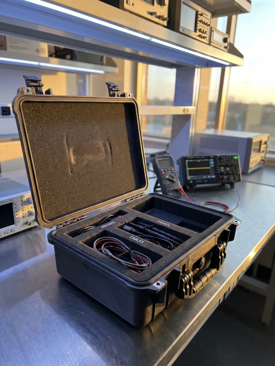
Loopers and cut-pile knives are the end effectors that form the pile, and they are the parts most often mishandled during packing. On a loop pile machine, the looper controls loop height; on a cut pile machine, the looper and the knife work together to sever the loop. Both share three traits, thin walls, a critical fit, and a sharp edge, and their packing requirement reduces to one word: isolation.
Isolation works at three levels. The first is part to part. A batch of loopers or cut-pile knives must sit one piece per slot, with slot pitch slightly greater than part thickness so each piece retains an independent degree of freedom and never contacts its neighbour face to face. Taping dozens of knives into a single bundle looks tidy and in fact presses the edges against each other, so any small relative movement in transit chips or scores them. The second is part to case. Hooks and knives must never touch the case wall or fasteners, and no loose hardware such as spanners or bolts belongs in the same case. The third is matched set isolation. A looper and its corresponding knife should travel as a pair in the position they will occupy on the machine, marked with a pairing number inside the liner, because a pair is geometrically matched and mixing positions changes the shear clearance and therefore cut quality.
Material and surface condition set the corrosion requirement. Loopers and cut-pile knives are usually made from high-carbon or alloy steel and heat treated, so the edge zone is both hard and chemically active, and corrosion blunts it directly. Rust on a cutting edge is not a wipe-it-off problem. Even light corrosion alters the microscopic edge geometry, so the cut becomes unclean and the pile surface turns fuzzy. Parts of this class should move into inhibiting packaging immediately after cleaning, should not be handled repeatedly with bare hands, and for long storage should be separated by a neutral interleaf that will not attack the metal.
4. Jacquard and servo needle selection: shock and moisture protection
Pattern capability on a modern tufting machine comes from the jacquard mechanism and the servo-driven needle selection system, and this class of component is fragile in a completely different way from the mechanical parts: it dislikes shock, dislikes humidity, and dislikes repeated temperature cycling in transit. The usual failure of a servo motor, encoder or controller in transit is not a cracked housing but a change in bearing preload, an encoder that loses calibration, a connector that works loose, or insulation resistance that falls in a humid environment. These defects tend to surface during commissioning, and tracing them consumes days while the start-up schedule slips.
Packing measures for this class include an individual seat made from a resilient, energy-absorbing grade, with enough contact area between seat and component to avoid stress concentration from point loads; desiccant inside the case with a humidity indicator card so condition can be judged at opening; no shared layer or shared case with heavy parts, because the inertial energy a heavy part carries under vibration is far above what an electronic unit tolerates; and protective caps over connectors and interfaces so debris cannot enter and terminals cannot distort. For servo and controller items going into long storage, respect the manufacturer's temperature and humidity band and run a power-on self-test plus a parameter backup comparison before reinstallation.
The mechanical side of the jacquard mechanism returns to ordinary mechanical logic: no contact with working faces, individual pockets, and set identity preserved. One reminder matters here. Jacquard parts are used as whole sets, and the geometric consistency of individual pieces directly affects pattern accuracy, so do not mix pieces from different sets and keep the set number visible inside the case.
5. Yarn feed system: yarn path surface, tension and tube straightness
The yarn feed system looks unglamorous and is in fact decisive for pile quality. Yarn runs at speed through feed units, yarn tubes and tension elements, and any burr, scratch or rust patch on a yarn path surface raises yarn hairiness, destabilises tension and causes yarn breaks, all of which appear in the fabric as uneven loop height and yarn ends. Treat the system as three part classes.
The first class is the feed unit and its wheels. These contain rotating elements, so the main transit risks are impact and contamination of bearings. Fit protective covers over rotating surfaces, keep them clear of other case contents, and handle bearing-equipped items under a shock limit appropriate to bearings so that raceways are not brinelled. The second class is the yarn tube. A thin-wall tube with flared or chamfered ends is prone to bowing and end deformation, so support it in multi-point slots that give surface contact, cap the ends with a soft material, and never let it share a layer with heavy parts. The third class is the yarn guide and tension bar. Slender rods with plated surfaces need their own slots with equal spacing, and ceramic eyelets or plated zones should face upward so they never contact the support surface.
Cleanliness of the yarn path matters as much as geometry. Machining debris, packaging particles and rust flakes produced in transit will travel with the yarn after installation and cause intermittent damage. Blow or wipe the yarn path items before packing and keep them enclosed afterwards, and avoid sharing a case with carbon steel. Where a batch contains both carbon and stainless steel items, zone them and add an isolation layer.
6. Working out support spacing and deflection control
Support design for long parts should be calculable rather than intuitive. The deflection of a simply supported beam under a distributed or mid-span load follows the standard relationship from mechanics of materials, in which deflection scales with the fourth power of span and inversely with section inertia. Two practical conclusions follow. First, reducing support spacing controls deflection far more effectively than increasing section size or changing material. Second, going from four supports to two raises deflection by an order of magnitude rather than in a straight line.
In practice you can work backwards from an allowed deflection target: establish the maximum permissible bow from the assembly tolerance, for example using the straightness requirement as the ceiling, then derive support count and pitch. Where an exact calculation is impractical, a conservative rule is to keep support pitch within one quarter of part length and to ensure the deflection between any two adjacent supports stays well inside the assembly tolerance.
| Component | Typical length band | Recommended support | Spacing logic | Case format |
|---|---|---|---|---|
| --- | --- | --- | --- | --- |
| Needle bar | 2 to 5 m | Multiple even supports plus axial stops | Within one quarter of length, with a deflection check | Long crate or steel frame case with moulded slots |
| Looper bar | 2 to 5 m | As needle bar, or layered separately | As above | Long case with layers |
| Yarn tube | 1 to 3 m | Surface-contact support slots | Support the ends, no overhang | Long case or long slot in a standard case |
| Tension bar | 0.5 to 2 m | Individual slots | Three supports or more including both ends | Standard case with liner |
| Jacquard assembly | Depends on width | Individual pockets plus damping seats | Not applicable, governed by shock control | Standard case with damping liner |
One point deserves emphasis: the stiffness of the case itself belongs in the calculation. A long crate deflects under stacking and lifting loads, and if the liner is rigidly fixed, case deflection becomes additional bending in the part. Long cases should therefore carry longitudinal stiffeners, and the liner should be attached flexibly or with clearance so that case deformation does not pass straight through to the component.
7. Case formats: long crates, steel frames and pallet consolidation
Case format follows three variables: part length, case weight and transport mode. Parts under two metres generally fit the standard case family, parts above two metres call for a dedicated long case, and items beyond four metres usually need a steel frame or a timber-steel composite structure combined with pallet consolidation. Do not compare unit price alone; weigh handling count, whether the case must be reused, and whether the destination has lifting capability.
A long timber crate is the most common answer, offering flexible dimensions at controllable cost for one-off shipments. Its weakness is that timber does not seal, so corrosion protection rests entirely on inner packaging and liner, and a barrier bag plus desiccant becomes mandatory. A steel frame case carries heavy and very long items well and simplifies lifting, but the steel needs corrosion treatment and must never contact the parts directly, or rust transfer and galvanic effects follow. Pallet consolidation suits multi-case shipments and removes individual lifts, which matters particularly for long parts, because every lift is a bending and twisting event.
Liner and divider choices feed back into case format. On projects shipping long parts with small parts, a common temptation is to reserve one end or side of the long case for the small items, but that shifts the centre of gravity and forces the lifting points to be recalculated. Separating long and small parts into different case families is safer, with the small-part cases made more adaptable through a removable divider system. If the project needs a dedicated case for an oversized part, judge the amortization first using our analysis of custom case mould and development cost.
| Transport attitude | Recommended lifting method | Required markings | Main risk |
|---|---|---|---|
| --- | --- | --- | --- |
| Horizontal (normal for long parts) | Two-point sling symmetric about the centre of gravity | This way up, centre of gravity, do not roll | Off-centre single-point lift creates combined bending and torsion |
| Vertical (a few special items) | Lift from the base, never drag sideways | This way up, anti-tip | High centre of gravity, overturning in transit |
| Layered stacking | Lift the whole layer, never extract a single item | Layer number, no single-item lift | Interlayer slip causing part-to-part collision |
| Pallet consolidation | Lift the pallet as a unit | Pallet centre of gravity, tier limit | Insufficient pallet capacity causing total instability |
8. Lifting, turning and transport attitude marking
A significant share of long-part risk occurs during lifting rather than during the journey. The dominant lifting damage is combined bending and torsion: a single off-centre sling places the part under both, and if the sling point sits near needle holes or a working face, local stress rises sharply. Mark lifting points on the long case at the centre of gravity and require two-point symmetric slings with sufficient width to spread pressure; wire rope in direct contact with case corners is not acceptable.
Turning is the other high-risk action. A long part may need its attitude changed during packing, loading or unloading, and a badly placed fulcrum produces a large transient deflection from self-weight. The disciplined approach is to define fulcrum position and turning direction before the operation and mark the permitted turning direction on the case. Once a needle bar is inside a case, site turning should be prohibited and the final transport attitude fixed at the packing stage instead.
For marking, apply pictorial symbols in line with GB/T 191, covering at minimum this way up, keep dry and do not roll, plus centre of gravity and lifting point markings where relevant. On batch-shipped projects, add the machine number and position range to the case. Marking turns knowledge held by one project manager into something any crew on site can execute, which matters on relocations involving multiple shifts and carriers.
9. Putting corrosion protection to work on tufting components
The metals on a tufting machine span a wide range: high-carbon and alloy steels in needle bars and knives, plated parts, stainless parts, painted parts and structural frames. When different metals and surface finishes share a case, the corrosion problem becomes markedly more complex, because inhibitors are metal selective. The first step is therefore not material selection but zoning: place high-carbon precision parts, stainless parts, plated parts and painted parts in separate zones so that corrosion products from one do not migrate onto another.
Step two is establishing the inhibiting atmosphere. For high-carbon items such as needle bars and knives, use a multi-metal inhibitor effective on both carbon and alloy steel, and confirm no acidic cleaning residue remains before packing. For plated parts choose a product that does not affect the coating, and for painted parts confirm the inhibitor will not soften or discolour the finish.
Step three couples humidity control with a barrier. Desiccant holds internal relative humidity down while the barrier slows the moisture exchange rate; neither works alone. As a practical matter, a long crate seals less tightly than a hard case, so long-part projects should size desiccant and barrier layers more conservatively than standard cases, and should include a humidity indicator card so the condition can be judged on arrival. The relevant test methods are described in our note on choosing a transport packaging test method.
Step four covers extended storage. For parts that will sit for months before installation, add a scheduled inspection and desiccant replacement arrangement on top of the inhibiting packaging, and keep storage in an area with stable temperature and humidity so that repeated condensation cycles do not undo the protection.
10. Vibration and resonance: the hidden risk for long parts
The other hidden risk for long parts is resonance. The natural frequency of a slender structure often falls inside the energy-dense band of road transport vibration, and if support spacing and part geometry happen to combine badly, local amplitude rises sharply, showing up as repeated rubbing between part and liner and fretting at needle holes and support faces. That damage is usually invisible at opening and then appears as depth deviation and an uneven pile surface once the machine runs.
Three controls apply. First, adjust the support arrangement so that changing the spacing shifts the natural frequency away from the energy-dense band. Second, add an energy-dissipating layer at the support interface so vibration energy is absorbed at the contact rather than leaving the part free to oscillate. Third, verify by test: place vibration monitoring points inside the long case, record the acceleration response during transport, and compare it against the part's stiffness characteristics to decide whether the support scheme needs revision. The sequencing and reference selection method is covered in our walkthrough of the ISTA transport testing procedure; for long parts, random vibration testing reflects real risk far better than a drop test.
One further point: the vibration response of a long part depends on case stiffness, liner density and how tightly it is strapped. Strap it too tightly and the part becomes part of the case, inheriting the case's motion; strap it too loosely and it moves freely inside. The engineering target is a state in which the part cannot shift relative to the case while the contact faces retain a small, controlled compliance.
11. Receiving inspection and pre-reinstallation checks
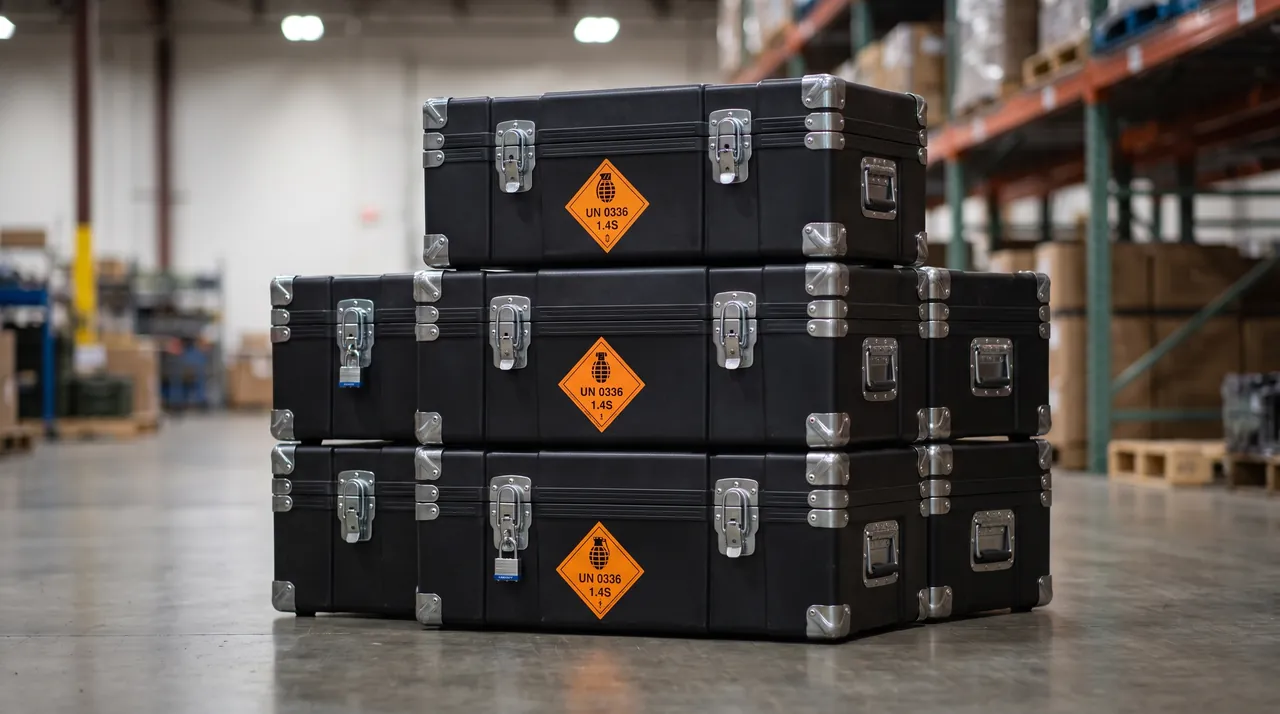
Receiving inspection for long parts differs from the ordinary routine because it must include straightness and fit checks, not just a visual pass. A four-step sequence works well.
Step one is the case and lifting condition check: look for deformation, damage, a triggered tilt indicator and intact lifting marks, and on a long case check for signs of twisting, since twisting usually indicates a bad lift. Step two is the packaging condition check: barrier integrity, humidity indicator status, liner displacement, and any support that has compressed. Step three is the geometric check on the parts: for needle and looper bars, check straightness on a surface plate or measure runout in segments; for yarn tubes, check straightness and end roundness; for loopers and cut-pile knives, sample the edges and fit faces and inspect under magnification for rust and burrs. Step four is the pairing check: verify looper and knife pairs by pairing number and jacquard sets by set number, confirming nothing has been mixed across positions.
The final check before reinstallation is cleaning. Once out of the case, long parts are exposed to the shop environment, so if the hall carries fly and dust, blow and wipe the needle hole zone, yarn path and rotating surfaces before assembly so that debris generated during transport never enters the machine. Parts stored beyond a defined period should have their corrosion condition re-confirmed against the packaging document before they are installed.
Acceptance criteria belong in the contract: straightness tolerance, appearance criteria, corrosion classification bands and the sampling plan. Writing down the standard for whether a part can be used protects both sides far better than an argument on the loading dock.
12. Quotation checklist, long-part traceability and customization
Quoting a long-part packaging project requires complete length and support information, otherwise the supplier can only return a generic price. Provide a part list with drawings covering name, material, net weight, length and section dimensions; the location of working faces, fit faces and needle hole zones; the maximum permissible bow or straightness requirement; the planned loading arrangement, whether one part per case, several parts in layers, or pallet consolidation; lifting conditions on site including crane capacity and fork access; transport mode and route including any oversized load restrictions and the number of transfers; destination climate and storage duration; whether the case must be reused; whether traceability by machine number and position is required; and delivery schedule with acceptance criteria.
JUNZHJIA, through Kexin New Materials (Guangdong) Co., Ltd., produces purpose-built cases for carpet tufting equipment. Needle and looper bars are laid out with support count and pitch derived from bar length, section and working face position, while thin-wall items such as knives are given single-piece slot liners marked with pairing numbers. The company undertakes OEM and ODM commissions and delivers through wholesale, agency and worldwide supply channels, issuing inspection and material documents as the contract provides. A typical route runs from component and length assessment, through support scheme and deflection review, to case format selection and prototyping, trial fit plus a lifting trial, transport testing where needed, batch production with inspection, and handover of packaging documentation. For an oversized needle bar, complete one trial fit plus a simulated lift before volume production, because lifting attitude cannot be validated from a drawing.
If the project also covers other textile processes, compare the handling differences described in the general framework for textile machinery component cases and in the guide to carpet printing and finishing component protection, so that packaging classes, lifting markings and numbering rules can be aligned across a multi-process relocation.
Frequently Asked Questions
Q: Can a bowed needle bar be straightened on site?
A: Generally not recommended, and in most cases it cannot be brought back to installation specification. Needle bar accuracy has two components: hole position and gauge establish the lateral location of every tufting needle, while straightness establishes constant penetration depth across the width. On-site straightening applies hydraulic or mechanical force and can only correct gross curvature, not restore straightness within assembly tolerance. More importantly, straightening introduces a new residual stress pattern inside the bar, and under sustained load and temperature variation after installation the bar may deform again, producing a straighten, deform, straighten cycle. The operation itself also requires clamping and force application, which tends to leave marks at needle holes and on working faces, adding a fresh defect. The engineering conclusion is that a bowed needle bar is treated as an irreversible failure and replaced. Prevention lives entirely in the packing stage: evenly spaced multiple supports, no unsupported mid-span, symmetric two-point lifting, and no turning on site. If the geometry must be assessed, involve the original manufacturer rather than applying force in the workshop.
Q: How many support points should a long-part case have?
A: It depends on part length, section inertia and the maximum permitted bow, so there is no universal number, but the design logic can be stated. Deflection in a slender beam scales with the fourth power of support span, which means support count affects deflection by orders of magnitude: moving from two supports to three can cut maximum deflection several fold, and four supports reduce it further. Two practical methods are used. The first sets an initial layout from the rule that support pitch should not exceed one quarter of part length, then checks deflection. The second works backwards from the maximum permitted bow to derive the support count. Note that more supports is not automatically better: if pitch becomes too small the supports turn into a dense set of constraint points, sliding travel concentrates at each contact and fretting wear accelerates, while case weight and lifting difficulty rise. Position supports where structural stiffness is highest, typically at end datums and stiffener locations, and add an energy-dissipating layer at each contact face.
Q: Can loopers and cut-pile knives be bundled together for shipment?
A: Bundling is not advisable. Both are thin-wall parts: a looper controls loop height through its geometry, and a cut-pile knife cuts with its edge. Bundling places the pieces in direct face-to-face contact, and even a small relative movement in transit chips edges, distorts hook tips and scores surfaces. Because the two are used as matched pairs, geometry damage to either one changes the shear clearance, which then affects cut quality and pile surface consistency. The correct method is one piece per slot, with slot pitch slightly greater than part thickness so each piece keeps an independent degree of freedom without face contact; a liner material that does not shed and does not attack the metal; and pairing numbers marked on the liner so positions are not mixed at reinstallation. Before packing, confirm the edge zones are clean and dry, and after packing avoid opening the case for repeated inspection, because every opening is another chance for exposure and recontamination.
Q: What needs attention when shipping jacquard and servo needle selection units?
A: The failure logic differs completely from mechanical parts, with shock and moisture as the two priorities. On shock, the main risk is not a cracked housing but a change in bearing preload, loss of encoder calibration and loosened connectors, all of which tend to surface only during commissioning and are expensive to trace. Use an individual seat made from a resilient, energy-absorbing grade with enough contact area between seat and unit to avoid stress concentration from point loads. Never share a layer or a case with heavy parts, because the inertial energy a heavy part carries under vibration far exceeds what an electronic unit can absorb. On moisture, add desiccant with a humidity indicator card and fit protective caps over connectors and interfaces. For units going into long storage, respect the manufacturer's temperature and humidity band and run a power-on self-test with a parameter backup comparison before reinstallation, so that a condition created in transit is not carried into the commissioning phase.
Q: A yarn tube does not look precision-made, so why does it need a purpose-built liner?
A: Because it directly guides the yarn, and its geometric condition shows up in the fabric as hairiness and tension fluctuation. A yarn tube is a thin-wall slender tube, often with a flare or chamfer at each end, and it suffers two damage modes in transit: overall bowing and end deformation. A bowed tube changes the contact angle of the yarn against the bore and increases tension variation, while a deformed end scrapes the yarn at the exit and produces hairiness and breaks. On top of that, any burr, rust spot or foreign body on the yarn path keeps damaging the yarn, and these defects appear in the fabric as uneven loops and yarn ends. The packing requirements follow: multi-point slots giving surface contact with the tube laid horizontally, soft end caps, no shared layer with heavy parts, and a blow-down or wipe of the yarn path before packing with the tube kept enclosed afterwards. Never ship yarn tubes in a case with carbon steel parts, because rust flakes will find their way into the bore.
Q: Which transport tests are relevant for long-part packaging?
A: For long parts, random vibration carries more weight than drop, because the dominant failure mode is slow bowing and fretting under sustained vibration rather than fracture from a single impact. A sensible sequence covers temperature and humidity conditioning to represent the shipping environment; random vibration as the key item, ideally with monitoring points inside the case recording the acceleration response; shock or drop sized by case weight to verify tolerance of lifting and loading impacts; and stacking compression to confirm that long-case deflection under stacked load does not pass into the part. Reference standards may be ISTA 3A, ASTM D4169 or a combination of GB/T 4857 sub-tests. Post-test judgement must include geometry: straightness on needle and looper bars, straightness and end roundness on yarn tubes, edges and fit faces on knives, plus inspection of support faces for compression marks and fretting evidence. Keep the monitoring data, because it becomes the basis for refining the support scheme on the next similar project.
Q: Does an oversized part always need a steel frame case?
A: Not necessarily, since each of the three formats has an applicable band depending on length, weight and handling conditions. A long timber crate offers flexible dimensions at controllable cost and suits one-off shipments of medium-length parts, but timber does not seal, so corrosion protection rests entirely on inner packaging and liner, and the crate's own stiffness is limited, which means it deflects under stacking and lifting and needs longitudinal stiffeners plus decoupling from the part. A steel frame case carries very long and very heavy items well and simplifies lifting, but the steel needs corrosion treatment and must not contact the parts directly, or rust transfer and galvanic effects follow. A timber-steel composite sits between the two and is often chosen where stiffness is needed but weight must be controlled. Base the decision on lifting count multiplied by load per lift multiplied by permitted deflection, and bring pallet consolidation into the comparison, because reducing individual lifts is itself a form of protection for an oversized part.
Q: How do we make sure parts go back into the right positions on arrival?
A: Build a traceability chain during packing. A three-level approach works well. The first level marks the case with machine number, component name and position range. The second marks the liner, adding pairing numbers or position numbers beside needle bar supports, looper slots and knife slots. The third is a document that travels with the shipment, giving a case-to-part-to-machine-position cross-reference plus any assembly relationship information the crew needs. Pairing numbers matter especially for loopers and cut-pile knives used as matched pairs, because mixing positions changes shear clearance, and set numbers matter for jacquard parts, because mixing sets compromises pattern accuracy. Packaging schemes for carpet tufting components under the JUNZHJIA brand are produced by Kexin New Materials (Guangdong) Co., Ltd., with marking levels and numbering rules configured to the customer's list, and with cooperation available through OEM and ODM commissions as well as wholesale, agency and global supply, issuing inspection and material documents to contract.
Conclusion and Further Reading
Four engineering judgements summarise carpet tufting component packaging. Slow bending dominates the failure of long slender parts, so the control lever is support layout and deflection review rather than thicker cushioning. Contact and corrosion dominate matched and edged parts, so the control lever is one-piece-per-slot isolation plus inhibiting packaging with desiccant. Resonance and fretting are the hidden risks on long parts, and they are found through support frequency adjustment, energy dissipation at contact faces and vibration monitoring. A large share of long-part risk occurs during lifting, which makes lifting marks and attitude rules as valuable as the case itself. Apply those four to support design, liner structure, lifting discipline and acceptance criteria, and needle bars and yarn feed parts will complete the relocation and return to production without a settling-in period.
Further Reading