

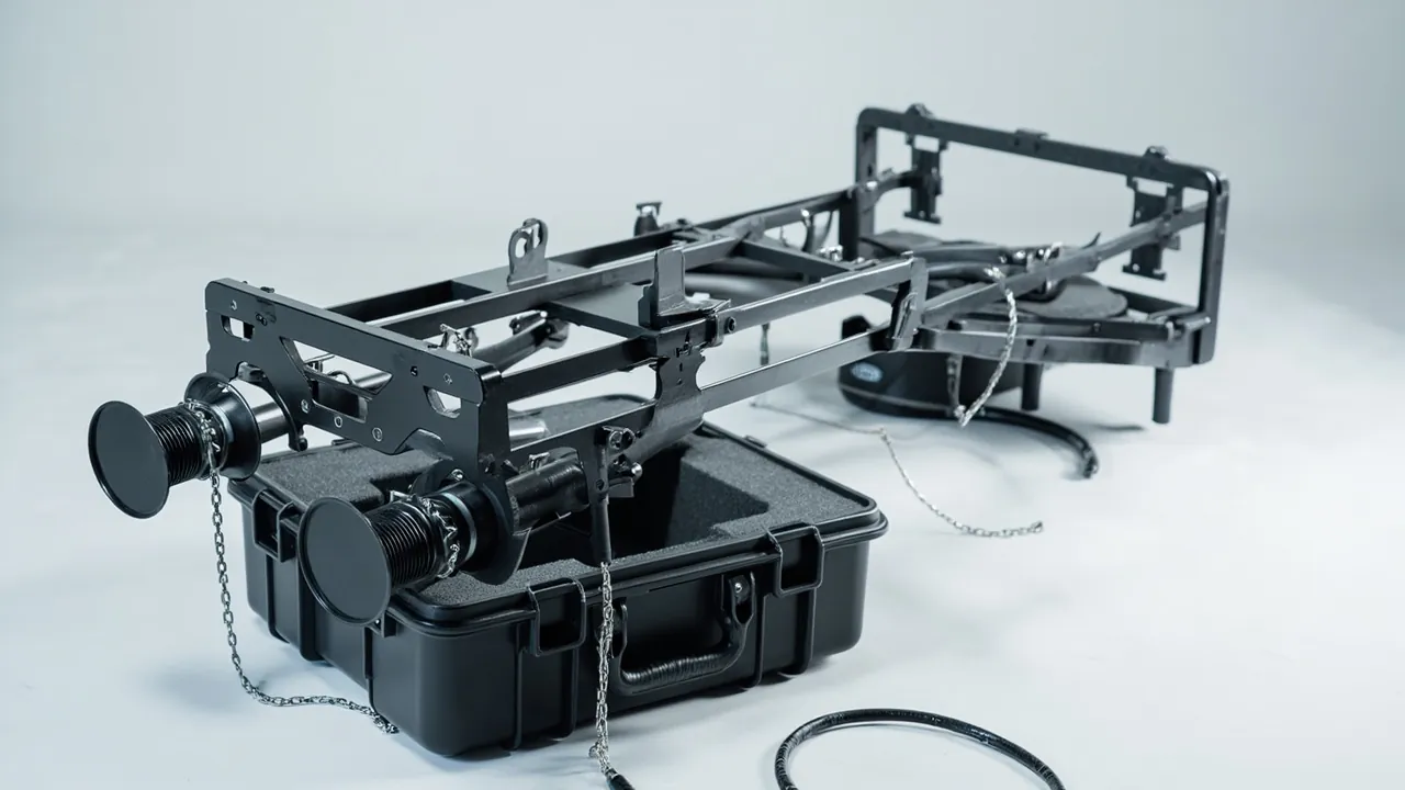
The most underestimated category of transit damage to stentering and tenter frame equipment is rust seizure. Rust spots appear between chain links, rollers turn stiffly, pins and bushings bind, white rust blooms on galvanised duct interiors, insulation sags after absorbing moisture, and the rail running surface develops pitting. At goods-in these often look like nothing more than a slightly weathered part, but once the machine runs they translate directly into chain creep, uneven tension left to right, pin-plate marks and shade variation across the fabric, and uneven hot-air distribution that makes heat-setting results unstable. The conclusion is clear: chains, rails, and ducts on stentering and tenter equipment combine large metal surface areas, precision fit clearances, and long thin-wall structures. The packaging objective is rust prevention, deformation prevention, and contamination prevention, which requires divided coiling, full-length support, sealed moisture control, and cleanliness protection in a dedicated parts case - not simple strapping and stretch wrap.
The interior of a stenter is one of the harshest environments in a dyehouse. The machine runs continuously at elevated temperature, fabric carries in moisture and auxiliary vapour, and the circulating hot air transports humidity, dye sublimates, softeners, and silicone oil mist onto duct walls, air nozzles, chain rails, and insulation surfaces. At high temperature these deposits carbonise and release acidic species, which are a direct cause of chain and rail corrosion. Between despatch and arrival the same parts face a second, slower attack: salt-laden air on a sea leg, rain and snow on inland legs, nightly condensation on cold steelwork inside a container, and repeated transfer handling. This article is written for stenter and tenter frame builders, chain and duct component suppliers, dyehouse retrofit buyers, and export project owners. It sets out graded protection schemes for chain, rail, and duct components, rust-prevention and cleanliness control points, insert and sealing design, validation routes drawn from published standards, and the acceptance checks to run on arrival; it closes with the engineering capability JUNZHJIA offers in custom inserts and OEM/ODM supply.
Table of Contents
- 1. Why Stentering and Tenter Frame Components Need a Dedicated Parts Case
- 2. Component List and Protection Grading
- 3. Failure Modes: Chain Seizure, Chain Elongation, Duct Deformation and Insulation Damage
- 4. Rust Prevention for Chains and Bearings: ISO 4406 Cleanliness Awareness
- 5. Size and Weight Boundaries: Chain Sections, Duct Sections and Rails
- 6. Case Structure and Material Selection
- 7. Insert Design: Coiling Restraint, Long-Item Support and Link Isolation
- 8. Protecting Ducts, Air Nozzles and Insulation Parts
- 9. Sealing and Ingress Protection: An IEC 60529 and GB/T 4208 View
- 10. Moisture and Rust Control in Hot, Humid Conditions
- 11. Corrosion and Salt Spray Validation: An ISO 9227 Perspective
- 12. Transport Vibration and Shock Validation: GB/T 4857 and ISTA
- 13. Stacking, Handling and On-Site Unpacking Management
- 14. OEM/ODM Customization, Acceptance and Maintenance
- Frequently Asked Questions
- Conclusion & Related Reading
1. Why Stentering and Tenter Frame Components Need a Dedicated Parts Case
Stenters and tenter frames are composite machines characterised by long dimensions, abundant metal, and high fit accuracy. Their chains and rails govern fabric width stability, and their ducts and nozzles govern hot-air uniformity, yet both of these main lines are easily spoiled by corrosion and deformation introduced at the packaging stage.
A chain keeps its accuracy in its clearances. A tenter chain consists of links, pins, bushings, and rollers, with link-to-link clearances typically measured in hundredths of a millimetre. Those clearances govern chain flexibility and pitch accuracy, which in turn govern pin-plate or clip positioning. Once corrosion products occupy the clearances, the effective clearance is forced open, so the chain elongates, creeps, or seizes, and once pitch control is lost, uniform width and tension left to right become impossible.
Rails and guideways keep their accuracy on their surfaces. Chain rollers roll on the rail surface, whose roughness and straightness govern running resistance and vibration level. Pitting and corrosion nodules from rust markedly increase rolling resistance and generate periodic impact.
Ducts and nozzles keep their accuracy in their cross-sections. A hot-air circulation duct relies on uniform internal flow area to deliver the same air volume to every zone. If a duct wall is dented or twisted in transit, or if insulation sags after absorbing moisture, the resistance distribution changes, temperature uniformity in the setting zone deteriorates, and the result is left-to-right shade variation and under-setting.
A large metal surface area means a large corrosion exposure. Chains, rails, ducts, and frame sections present an enormous metal area, and most of it carries a surface treatment such as blackening, galvanising, chrome plating, or painting. Once these treatments are scored in transit, the score becomes a pitting initiation site that spreads quickly in a humid environment.
Chain creep and uneven left-right tension is the hardest responsibility to assign. Chain creep or left-right shade variation on the fabric often surfaces weeks after start-up, by which time material, machining, packaging rust prevention, and on-site contamination have intertwined, and no one can tell whether the link clearance was forced open by corrosion or the site rail was loaded unevenly. Writing the rust-prevention process parameters and the arrival humidity-indicator-card reading into the case file, then comparing them with the on-opening chain flexibility check, returns the dispute to data and forms a traceable chain of responsibility.
Key reminder: stenter component damage is cheap to prevent and expensive to reverse, and it usually appears as degraded performance rather than outright failure, which makes it easy to overlook and easy to escalate into a long-running quality dispute.
For stenter and tenter frame builders and component suppliers, the parts case also acts as standardised tooling. Building a standard case series by chain size and duct section length significantly reduces storage and circulation cost, and the reuse assessment method is discussed in protective case service life and reuse years.
2. Component List and Protection Grading
Sensitivities differ sharply between stenter components, so grade each item before packing rather than grouping by size.
| Component | Typical material / structure | Critical sensitivities | Recommended protection |
|---|---|---|---|
| --- | --- | --- | --- |
| Tenter chain (full run or sections) | Alloy steel links, pins, rollers | Link clearances, pin corrosion, roller rotation | Large-diameter coiling + rust-preventive oil seal + reel separation |
| Individual links and spares | Machined alloy steel | Fit surfaces, pin bores | Compartment box + oiled paper wrap + one per compartment |
| Chain guideway and rail | Section steel or alloy rail | Running-surface roughness, straightness | Full-length support + running-surface guard + end caps |
| Pin plates and clips | Alloy or stainless steel with springs | Pin tips, spring leaves, clamping faces | Vertical or flat compartments + pin-tip sleeves |
| Duct and air pipe sections | Galvanised or stainless thin sheet | Cross-section deformation, plating scores | Internal forming ring + end rings + external guards |
| Air nozzles and nozzle plates | Thin sheet steel or stainless | Nozzle slot gap, flatness | Forming cradle + slot guards |
| Hot-air fan impeller | Stainless or aluminium | Blade deformation, dynamic balance | Isolated cavity + mandrel support + blade guard ring |
| Fan shaft and bearing housing | Alloy steel with bearings | Bearing corrosion, shaft-end impact | Isolated cavity + shaft sleeve + rust-preventive oil seal |
| Drive sprockets and gears | Alloy steel | Tooth flanks, keyways | Compartments + flank protection + anti-rust paper |
| Tensioning devices and cylinders | Alloy or aluminium with seals | Piston rod surface, air ports | Isolated cavity + rod sleeve + port plugs |
| Inverter and temperature modules | Sheet metal, PCB | Moisture, ESD, vibration | Barrier bag + ESD bag + damped support |
| Temperature and humidity sensors | Precision electronics, RTD probes | Probe, cable, insulation | Dedicated small cavity + probe sleeve + ESD |
| Insulation panels and blankets | Mineral wool or aluminosilicate with facings | Moisture sag, facing deformation | Sealed moisture barrier + flat stacking limit + no heavy load |
| Fasteners and special bolts | Alloy or stainless steel | Threads, plating | Compartment box + anti-rust paper |
The table shows that clearance rust prevention, long-item deformation prevention, and insulation moisture protection form the three protection themes for stenter components, while cleanliness control runs through every metal item.
3. Failure Modes: Chain Seizure, Chain Elongation, Duct Deformation and Insulation Damage
Failures caused by packaging defects typically surface weeks after the machine starts running, and they are hard to trace. The main modes fall into eight groups.
Chain seizure and jamming. Link clearances are extremely small, and corrosion products fill them. The mild outcome is stiff rotation and increased running resistance; the severe outcome is local seizure that produces chain creep and pitch irregularity.
Chain elongation and pitch loss. Once corrosion establishes itself in the clearances and persists, relative wear between pin and bushing accelerates and the chain elongates overall. Elongation displaces pin plates, so width and tension differ left to right, producing diagonal crease marks and pin-plate marks on the fabric.
Roller surface pitting and spalling. Rollers run in rolling contact with the rail, and corrosion pits become fatigue initiation sites. Under long-term alternating contact stress, material spalls around the pits, generating periodic impact and noise.
Rail surface pitting and corrosion nodules. Pitting and local nodules on the rail surface markedly increase rolling resistance and cause periodic vibration in the chain run, which further accelerates chain wear.
Duct cross-section deformation and internal fouling. Thin-wall ducts dent under compressive load or dropping in transit, altering air volume distribution. Internal corrosion and plating scores then accelerate fouling at high temperature, creating local deposits that disturb air velocity uniformity.
Insulation moisture sag. Mineral wool and aluminosilicate insulation absorb moisture, which markedly raises thermal conductivity and reduces dimensional stability, appearing as local sag. The sag short-circuits hot air and degrades temperature uniformity in the setting zone.
Fan impeller deformation and loss of dynamic balance. An impeller is a high-speed rotating part, and even slight blade deformation destroys dynamic balance, causing vibration and premature bearing failure.
Sensor and electrical moisture failure. Stenter temperature control depends on RTDs and thermocouples. Moisture causes insulation loss and reading drift, directly affecting process temperature control.
4. Rust Prevention for Chains and Bearings: ISO 4406 Cleanliness Awareness
To design rust prevention correctly, you must first understand what conditions corrosion requires.
Three requirements for corrosion. Metal corrosion requires three conditions at once: an electrochemically active surface with no effective protective film, an electrolyte in the form of a water film or salt-bearing water film, and oxygen or another depolarising agent. Eliminating any one of the three markedly reduces the corrosion rate. The logic of packaging for rust prevention is therefore to eliminate the electrolyte, which in practice means controlling humidity.
The critical relative humidity concept is worth unpacking. Iron and steel have a critical relative humidity, empirically around 60 percent; below it no continuous water film can form and the corrosion rate drops sharply. Holding the atmosphere inside the case below 40 percent is therefore the design target, and a humidity indicator card is the cheapest way to prove it was met.
Cleanliness and particulate contamination. Chains and bearings are moving fit pairs in which particulate contamination accelerates wear. Cleanliness can be managed along the ISO 4406 particle contamination level approach, which characterises cleanliness by counting particles in different size ranges per unit volume of oil. Although ISO 4406 primarily addresses hydraulic oil, its particle-count grading method applies equally well to specifying assembly and packaging cleanliness for chains and bearings.
Multiple layers of rust prevention. First, the component: clean, dry, and apply rust-preventive oil or peelable film, with chains oil-dipped or oil-dripped. Second, the unit: wrap in oiled paper, then seal into a foil bag with desiccant and a humidity indicator card. Third, the case: gaskets plus a pressure equalisation valve plus slow-release desiccant. Fourth, management: shorten exposure time, control packing-area humidity, and prohibit bare-hand contact with precision fit surfaces.
Treating stainless steel differently. Stainless steel does not develop red rust but can still suffer pitting and crevice corrosion, especially when free-iron contamination arises from mixing with carbon steel parts. Material zoning is therefore the most easily overlooked and yet the most effective single rust-prevention measure.

5. Size and Weight Boundaries: Chain Sections, Duct Sections and Rails
Stenter and tenter components are predominantly long, so packing strategy must be graded by length and stiffness.
| Class | Typical components | Unit size / weight | Packing strategy | Key risk |
|---|---|---|---|---|
| --- | --- | --- | --- | --- |
| Micro | Links, pins, sensors | Under 0.2 m / under 2 kg | Compartment box inside a master case | Loss, mixing, corrosion |
| Small | Pin plates, clips, sprockets | 0.2 to 0.5 m / 2 to 20 kg | Divided cavity + soft liner + anti-rust paper | Pin-tip damage, flank impact |
| Medium | Fans, tensioners, nozzle sections | 0.5 to 2 m / 20 to 100 kg | Isolated cavity + forming support | Impeller deformation, rod scoring |
| Large | Chain sections, rail sections, duct sections | 2 to 6 m / 100 to 400 kg | Full-length multi-point support case + lifting points | Bending, cross-section deformation |
| Extra large | Complete chain reels, frame sections | Over 6 m / over 400 kg | Reel-type base case + dedicated cradle | Instability, insufficient coiling diameter |
Four grading principles apply. First, grade by length: components over 2 m need at least three support points, with spacing held to an empirical maximum of one third of component length to avoid first-mode bending resonance and self-weight creep. Second, grade by fit accuracy: chains and bearings have extremely small clearances, so bare-hand and bare-steel contact must be avoided and dedicated rust prevention applied. Third, grade by thin-wall character: ducts and nozzles need internal forming or external guarding to hold their cross-section, and slings must never be applied directly around a thin-wall section. Fourth, grade by surface treatment: galvanised, chrome-plated, blackened, and painted surfaces become corrosion initiation sites once scored, so isolation film should be applied.
6. Case Structure and Material Selection
Stenter parts cases must balance large size, heavy load, and rust prevention, so the selection logic differs markedly from general equipment cases.
| Structure | Typical material | Size / load capability | Advantages | Suitable for |
|---|---|---|---|---|
| --- | --- | --- | --- | --- |
| Injection-moulded hard case | PP or PE | Small to medium / low to medium | Light, well sealed, nestable | Links, sensors, tensioners |
| Rotomoulded case | PE (LLDPE) | Medium to large / medium to high | Impact resistant, large sizes possible | Pin plates, sprockets, nozzle sections |
| Blow-moulded case | HDPE | Medium / medium | Moderate cost, good stiffness | General components |
| Honeycomb sandwich panel case | Aluminium skins with honeycomb core | Large / medium to high | Very high specific stiffness, dimensionally stable | Rail sections, duct sections |
| Profile frame case | Aluminium profile frame with panels | Large / high | Full-length support, lifting points possible | Chain sections, long ducts |
| Reel-type base case | Steel or aluminium reel with case body | Large / very high | Easy chain coiling and lifting | Complete chain reels, heavy parts |
Four selection criteria. First, sealing and moisture control capability: since the core of rust prevention is humidity control, gasket quality and pressure equalisation valve provision matter more than case strength. Second, specific stiffness: for large long items, honeycomb sandwich or profile frame structures are preferable. Third, surface treatment and corrosion protection: the case's own metal hardware, including hinges, latches, and lifting points, also needs corrosion design, and material and surface treatment requirements should be specified along the lines set out in stainless hinges, latches and gaskets selection. Fourth, static control and flame retardancy: cases holding control boards and sensors should have surface resistance assessed and material selected with reference to the UL94 flammability classification; see ESD shielded protective case design.
7. Insert Design: Coiling Restraint, Long-Item Support and Link Isolation
The insert is the functional core of a parts case. For stenter components it must solve four problems at once: location, rust prevention, isolation, and deformation prevention.
Chains: large-diameter coiling, reel separation, oil seal. Chains should be coiled at a large diameter and restrained, with the coiling diameter empirically not less than 30 times the chain pitch, to limit bending stress in the links. Adjacent reels must be fully separated by dividers so they cannot rub. Chains should be cleaned, dried, and oil-dipped before coiling, then sealed into a rust-preventive bag with desiccant.
Rails and guideways: full-length multi-point support plus running-surface guards. Rails are long and must be supported at no fewer than three points, with elastic soft liners at the support surfaces. The running surface, which is the working face, must receive a soft guard and must never contact a hard object. End caps prevent impact damage and burrs.
Duct sections: internal forming ring plus external guards. A thin-wall duct section should receive an internal forming ring at each end to hold the cross-section, and external guards to prevent scoring and denting. Long duct sections must be supported on a rigid base rather than laid directly on other components.
Pin plates and clips: pin-tip sleeves plus vertical or flat compartments. Pin tips are extremely fine precision features that bend or break on impact and require tip sleeves or dedicated carrier plates. Spring leaves must not be held under sustained compression, to avoid stress relaxation.
Links and pins: compartment boxes with one piece per compartment. Precision fit parts must be separated individually, because sustained micro-motion in transit wears the fit surfaces.
Insulation parts: flat stacking limits and no heavy load. Insulation panels and blankets should be stacked flat with a limited number of layers and protected by a sealed moisture barrier against sag.
Fan impellers: mandrel support plus blade guard ring. The impeller should be centred on a mandrel with axial restraint, and an outer guard ring should prevent blade loading. Selection of related cushioning and support materials is covered in cushioning liner materials and structure design.
8. Protecting Ducts, Air Nozzles and Insulation Parts
The duct system governs both energy efficiency and temperature uniformity in a stenter, and its protection is often neglected.
The failure mechanism of thin-wall structures. Ducts and nozzles are commonly made from 0.6 to 1.5 mm galvanised or stainless sheet with low bending stiffness. Local compression, dropping, or sling strapping produces plastic dents that do not recover after unloading. A dent changes the internal flow area and therefore the resistance distribution.
How to protect the cross-section. The port is the weakest part of a thin-wall structure, so a dedicated internal forming ring or shaping block should be inserted to resist squeezing. Long sections should use rigid cradles with spacing no greater than one third of section length.
Protecting platings and the inner wall. Once a galvanised layer is scored it loses its sacrificial anodic protection and becomes a starting point for white rust and then red rust. Internal corrosion products combine with auxiliaries and silicone oil carried out by the fabric at high temperature to form coke that is difficult to remove. The inner wall should therefore be kept clean and protected with isolation film.
Protecting the nozzle slot gap. The nozzle slot gap determines air velocity and penetration and is a precision geometric feature that needs a guard bar to prevent impact deformation.
Quantified requirements for insulation moisture protection. Moisture uptake by insulation is a hidden but serious problem. Packaging should use sealed foil bags with desiccant and a humidity indicator card, and the arrival reading should be used as acceptance evidence. For long-term storage, control ambient humidity.
Cleaning residual auxiliaries and silicone oil. Ducts and nozzles removed from service may carry auxiliaries, silicone oil, and dye coke that must be cleaned and dried before packing; otherwise they continue to absorb moisture inside a sealed case and become a corrosion source. The cleaning method is described in protective case cleaning and maintenance practice.
9. Sealing and Ingress Protection: An IEC 60529 and GB/T 4208 View
Ingress protection is an important specification for stenter parts cases, but it is important to understand what it does and does not prove.
IEC 60529 and GB/T 4208 are the same system. IEC 60529 and China's GB/T 4208 define identical IP code meanings: the first characteristic digit denotes protection against solid foreign objects and dust (0 to 6) and the second denotes protection against water (0 to 9). Common ratings for stenter cases are as follows.
| Rating | Dust | Water | Meaning for stenter components |
|---|---|---|---|
| --- | --- | --- | --- |
| IP54 | Limited dust protection | Splash resistant | Short in-plant transfers, dry environments |
| IP65 | Dust tight | Jet-water resistant | General inland transport and plant transfers |
| IP67 | Dust tight | Short immersion (1 m for 30 min) | Marine transport, rain and snow, wet handling |
| IP68 | Dust tight | Continuous immersion (per manufacturer) | Extreme duty, to be specified separately |
Three points must be clarified. First, an IP rating is not a rust-prevention rating. IP67 proves only that water cannot enter, yet moisture already inside the case, from residual water on components, moisture absorbed by the insert, or ambient air trapped at closing, can still cause corrosion. Rust prevention therefore depends on the combination of drying, sealing, and desiccant, not on the IP rating alone. Second, IP ratings do not cover mechanical deformation or shock, which must be validated using ISTA or GB/T 4857. Third, a fully sealed case develops an internal-external pressure differential as temperature and barometric pressure change, which can make opening difficult or draw the gasket out of shape, so long sea and air routes normally justify a pressure equalisation valve, as discussed in protective case pressure equalisation valve function and selection.
The tension between sealing and venting. One frequently overlooked fact is that moisture inside a case must either escape or be absorbed. If components are sealed in before they are fully dry, the seal simply locks the moisture in. The process order must therefore be dry first, then seal, then add desiccant - not seal first and rely on the seal to keep water out.
10. Moisture and Rust Control in Hot, Humid Conditions
Stenter components pass through several humidity regimes between despatch and commissioning, and the design must address each.
Three typical humidity regimes. The first is the marine case: high salt fog, high humidity, large day-night temperature swings, and the possibility of condensation inside a container. The second is the inland case: rain and snow, day-night temperature swings, and temporary open-air storage. The third is the shop case: high temperature and high humidity, with moisture and auxiliary vapour carried out by the fabric. Packaging should be designed for the first two; the third is mainly addressed by the machine's own corrosion design and on-site maintenance.
Condensation mechanism and countermeasures. Condensation occurs when a surface temperature falls below the dew point. A sea container heats under solar load by day and cools rapidly at night; internal air is humid, and metal parts, having high thermal mass, lag in cooling and become condensation surfaces. Countermeasures include raising case thermal resistance through sandwich or insulated liners, controlling internal humidity with desiccant, and avoiding cases placed directly against container walls and floors.
Quantified desiccant provision. Desiccant quantity should be estimated from case volume, sealing performance, transit duration, and target humidity. In engineering practice a desiccant quantity per unit volume is used as an empirical parameter and then corrected against actual humidity indicator card readings. The key practice is to use the humidity indicator card as a verification tool, forming a configure, measure, correct loop.
Selecting and removing rust-preventive oil. Rust-preventive oil must balance protection duration against ease of later removal. For parts that will be cleaned before assembly, a solvent-borne or alkali-removable oil is suitable; for peelable protective film, ensure no adhesive residue remains after peeling. Chains should preferably be oil-dipped or oil-dripped so that the pin and bushing clearances are protected internally as well.
Prohibited practices. Do not touch precision fit surfaces with bare hands, since sweat is a strong electrolyte. Do not open or pack in rain or in high ambient humidity. Do not seal components that have not been dried. Do not mix stainless and carbon steel parts. Do not use sulphur-bearing rubber or low-grade regrind foam as insert material.
11. Corrosion and Salt Spray Validation: An ISO 9227 Perspective
Both the dyehouse and the marine route are corrosive environments, so salt spray testing is an important basis for validating corrosion protection.
ISO 9227 neutral salt spray (NSS). The standard specifies continuous spraying with a 5 percent sodium chloride solution at pH 6.5 to 7.2 and a chamber temperature of 35 degrees Celsius, with common durations of 24, 48, 96, 240, and 480 hours. Note that there is no simple conversion between salt spray duration and outdoor service life; the test is primarily used for relative comparison between candidate schemes and for consistency control.
Test subjects should be layered. Validate separately: the case metal hardware (hinges, latches, lifting points, profiles); the insert and gasket materials; and representative component samples such as a chain link coupon, a galvanised sheet coupon, or a carbon steel fastener. Only layered data can localise the corrosion source.
Optional advanced methods. For export projects on tropical and oceanic routes, cyclic corrosion testing that alternates salt spray, drying, and humid phases reflects real atmospheric corrosion behaviour more closely than continuous salt spray.
Result criteria. Judgement is normally based on time to red rust appearance or on corrosion spot count and rating per unit area. The procurement agreement should specify the test method, duration, acceptance criteria, and disposition of non-conforming results rather than simply requiring that the product "shall pass a salt spray test".
Specific relevance to galvanised parts. A zinc coating provides sacrificial anodic protection, and its effectiveness depends on coating thickness and integrity. Scored areas and cut edges corrode first, so protecting coating integrity is more cost-effective than increasing coating thickness - which is the direct justification for score-prevention design in packaging.
12. Transport Vibration and Shock Validation: GB/T 4857 and ISTA
Mechanical damage to chain and duct components cannot be judged by eye, so reproducible test methods are essential.
Validation baseline for stenter and printing-line spares. Chain rails, fan impellers and ducts degrade mainly through vibration and impact rather than static load, so the plan should lead with GB/T 4857 random-vibration and horizontal-impact clauses and add stacking and water-spray only as the route demands. Sequence it by distribution environment with ISTA (Series 3 for general simulation, Series 6 for a specific carrier) or, for North-American orders, ASTM D4169 built from the distribution cycle. Implementation details — GB/T 4857 guidance, ISTA selection and ASTM D4169 distribution-cycle notes — are linked at the end of this article.
Four checks that must follow testing. First, functional check: chain flexibility and running resistance, fan impeller rotation, sensor readings. Second, geometric check: rail straightness, duct cross-section shape, impeller roundness and flatness. Third, corrosion check: presence of condensate traces inside the package, humidity indicator card reading, and rust spots on metal surfaces. Fourth, cleanliness check: presence of debris and foreign objects in the insert.
MIL-STD-810H and the tenter duct temperature-humidity cycle. Tenter ducts and chains run long-term in 150–220 °C hot air and auxiliary-laden vapour, where their coatings and greases must hold performance through "high-temperature – ambient – high-humidity" alternation; the temperature-humidity cycling, humid heat and salt-fog methods of MIL-STD-810H can reproduce the temperature-humidity shock a duct section sees when entering and leaving the hot zone. Citing it as the method library for the duct-and-chain "temperature-humidity cycle" environmental test is accurate; claiming on that basis that the case is "military certified" or that the product has military approval is wrong. See MIL-STD-810H environmental testing and protective case compliance.
The cases described here serve only as outer transport packaging. They are not part of the equipment's own design or manufacturing, and do not alter the equipment's mechanical or process performance; safety and certification requirements for the equipment itself remain governed by the applicable regulations and standards.
Chain grease low-temperature flexibility and duct condensate. Chain coils shipped to cold regions face hardened grease that raises running resistance and, at low pressure on a plateau, a magnified pressure differential across the case; the duct sections are the opposite risk — warm moist air trapped inside condenses when the case cools, leaving water traces that start corrosion. For cold or high-altitude destinations, both the chain grease's low-temperature flexibility and the duct-section condensate risk must be assessed; see protective cases in extreme temperature environments.

13. Stacking, Handling and On-Site Unpacking Management
Stacking strength must be calculated for the worst case. The number of stacked layers inside a sea container is usually greater than for domestic transport, and the bottom case carries the upper load plus sustained vibration for a long period. Calculate bottom load as actual stacked layers multiplied by total unit weight multiplied by a safety factor of not less than 2, and mark the maximum stacking layers on the case.
Lifting and forklift practice. Heavy long-item cases must be marked with lifting-point positions and permitted sling configurations (four-point or two-point), and single-point lifting and diagonal pulling are prohibited. Never sling a chain or duct directly with wire rope; load must pass through case lifting points or dedicated lifting gear. Wheeled heavy-duty case selection is covered in protective case wheels and trolley handle structure.
Attitude and tilt indication. Chain reels and long duct sections have attitude requirements. Mark all four sides with up-arrow and do-not-invert symbols, and fit a tilt indicator for arrival assessment.
A six-step unpacking procedure. First, record case appearance and tilt-indicator status. Second, photograph the seal and labels. Third, read and record the humidity indicator card. Fourth, remove small parts and electrical parts before long and heavy items. Fifth, check off the packing list item by item and inspect sleeves, plugs, and insert integrity. Sixth, carry out a manual flexibility check on chains and a visual and dimensional check on rails and ducts, and file the data.
The rust-prevention clock after opening. Once a rust-preventive package is opened, protection begins to decay. Installation should be completed, or the parts transferred to a controlled storage environment, as soon as possible after opening, rather than leaving them exposed to humid shop air. If temporary storage is necessary, re-seal the package and replenish the desiccant.
Case recovery and reuse. Before reuse, clean, dry, and inspect gaskets and insert wear; replace inserts showing compression marks or powdering. Lock assessment is covered in protective case lock and customization options, and divider reconfiguration in protective case removable divider system.
14. OEM/ODM Customization, Acceptance and Maintenance
A six-step customization process. First, requirement input: component list, 3D models or physical parts, weight and centre of gravity, transport route, environmental conditions, and rust-prevention and cleanliness requirements. Second, scheme design: case structure, coiling or support insert layout, rust-prevention and moisture strategy, and desiccant provision. Third, prototyping: inserts are commonly produced by CNC-milled EVA or die-cut lamination, and prototyping verifies fit tolerance and ease of removal; process detail is covered in EVA foam insert custom process. Fourth, functional validation: sealing (IP rating), vibration and shock (ISTA or GB/T 4857), salt spray (ISO 9227), and measured moisture-control performance. Fifth, pilot batch and acceptance. Sixth, volume production and delivery.
Acceptance sampling method. For volume deliveries, AQL sampling acceptance is recommended, with inspection items and acceptance quality limits defined for appearance, dimensions, fit, sealing, marking, and desiccant provision; method and clause design are covered in custom case acceptance and AQL sampling plans. A material identification mechanism should also be established to prevent low-density regrind EVA being passed off as high-density EVA or ordinary PE being passed off as LLDPE; see how to identify genuine versus inferior protective cases.
Tooling and cost assessment. Where a component family is large, the amortisation model for dedicated tooling should be assessed; see protective case custom mould cost analysis. Supplier evaluation criteria are covered in how to choose a protective case OEM factory.
Maintenance and life management. Maintain a case register recording the date in service, number of trips, desiccant replacement history, gasket replacement interval, and insert replacement history; service life assessment is covered in protective case service life and reuse years.
JUNZHJIA engineering capability. JUNZHJIA, manufactured by Kexin New Materials (Guangdong) Co., Ltd., provides protective case customization for stenter and tenter frame builders and for chain and duct component suppliers. The company can design large-diameter coiling inserts with reel separation to suit specific chain sizes, design full-length multi-point support with port forming rings to suit duct section lengths, supply matched gaskets and pressure equalisation valves by model, provide test documentation for IP rating, vibration and shock, and salt spray projects, and support volume wholesale, agency, and OEM/ODM cooperation. For export projects, labelling, instructions, and traceability coding can be customised to destination-country requirements.
Frequently Asked Questions
Q: Why do stenter chains tend to develop stiff links after transport, and how does packaging relate to it?
A: A stiff link means relative rotation between chain links has become very difficult or has seized, and the root cause is a mixture of corrosion products and contaminants inside the link clearances. Packaging relates to it directly for four reasons. First, clearances are extremely small, typically only hundredths of a millimetre, so any corrosion product rapidly fills them. Second, factory rust prevention may be inadequate: if a chain is not oil-dipped or oil-dripped, the pin and bushing clearances lack an effective protective film and rust as soon as moisture is present. Third, package humidity control may fail: if components are sealed in before they are fully dried, or if the case does not seal well and carries no desiccant, internal moisture becomes a continuous corrosion source. Fourth, transport conditions aggravate the problem, since marine salt fog, container condensation from day-night temperature swings, and sustained vibration act together to accelerate corrosion and compact the corrosion products inside the clearances. Prevention includes cleaning and oil-dipping the chain before storage, coiling at a large diameter, separating reels, using foil bags with desiccant and humidity indicator cards, fitting a pressure equalisation valve, and installing promptly on arrival with a manual flexibility check.
Q: Why must chain coiling diameter be limited, and how is a sensible value determined?
A: Because too small a coiling diameter introduces excessive bending stress at the links and pins. A chain is a structure of rigid links connected by pins, and each link must rotate through an angle relative to its neighbour as the chain is coiled; the angle increases as the coiling diameter decreases. A larger angle raises contact pressure between pin and bushing, and if corrosion or particulate contamination is also present, wear accelerates markedly. For a chain that has been oil-sealed, too small a coiling diameter also squeezes the oil film out of the clearances, which actually reduces protection. In engineering practice, a coiling diameter of not less than 30 times the chain pitch is a reasonable empirical starting point, but for roller chains with attachments the value should be verified against link height, attachment protrusion, and pin diameter, and enlarged where necessary. Three further points matter: maintain even tension while coiling so that no local slack allows links to press on each other; fully separate adjacent reels with dividers; and support the reel centre on a rigid mandrel or cradle so that chain self-weight does not bear on the lower layers for a long period.
Q: How should thin-wall ducts and nozzles be protected so they do not deform?
A: The core principles are to limit local load, hold the cross-section, and avoid sling strapping. Five measures apply. First, internal forming at ports: a duct port is the weakest part of a thin-wall structure, so a dedicated forming ring or shaping block should be inserted so that external force is carried by the internal structure rather than by the wall. Second, full-length support: duct sections over 2 m need at least three support points, with spacing at an empirical maximum of one third of section length and elastic soft liners to avoid point contact. Third, external guards: fit guard bars or plates on the outer surface so that contact with other components or the case wall cannot dent the sheet or score the plating. Fourth, never strap directly: wire rope, cable ties, or slings create concentrated pressure at the contact point and cause immediate plastic dents, so load must pass through case lifting points or dedicated lifting gear. Fifth, protect the nozzle slot: the slot gap is a precision geometric feature and needs a guard bar against impact deformation. Attention should also be paid to internal cleanliness and dryness, because internal corrosion products combine with auxiliaries and silicone oil at high temperature to form coke that is very hard to remove.
Q: How long does rust-preventive packaging last, and how much desiccant should be used?
A: The protection period is determined jointly by component surface condition, sealing performance, desiccant provision, and external environment, so there is no single universal number of days. A useful way to reason about it is this: if components are fully dry, the case is sealed to IP67 with a pressure equalisation valve, desiccant provision is adequate, and temperature swings in transit are moderate, protection will normally cover a standard sea voyage plus warehousing; conversely, if components are sealed in wet or the gasket fails, protection may last only days. The engineering approach to desiccant quantity is to calculate the moisture to be absorbed from case internal volume, target relative humidity, transit duration, and temperature conditions, convert that into a mass of the chosen desiccant using its effective absorption rate, and then correct the result against actual humidity indicator card readings. Three practices are recommended: place a humidity indicator card in every sealed unit and treat the arrival reading as acceptance evidence; for long-duration or high-value projects, run a simulated transport validation to confirm the desiccant provision; and specify the arrival humidity limit and the disposition of exceedance in the procurement agreement. This turns desiccant provision from an estimate into a verifiable parameter.
Q: What protection rating should a parts case achieve? Is IP65 enough?
A: It depends on the transport route and the component characteristics. IP65 means dust tight and jet-water resistant, adequate for general inland transport and plant transfers. IP67 means dust tight and able to withstand immersion in 1 metre of water for 30 minutes, and suits marine transport, rain and snow exposure, wet handling, and temporary open-air storage; IP67 is recommended for large metal items such as chains, rails, and ducts, and for cases containing electrical components. IP68 requires continuous immersion and is normally needed only in special duty. Three points must be emphasised. First, an IP rating is not a rust-prevention rating: IP67 proves only that water cannot enter, while moisture already inside the case, from residual water on parts, moisture absorbed by the insert, or ambient air trapped at closing, can still cause corrosion. Rust prevention must therefore rely on the combination of drying, sealing, and desiccant. Second, IP ratings do not cover mechanical shock and deformation, which must be validated by ISTA or GB/T 4857. Third, full sealing creates a pressure differential problem, since temperature and barometric changes can make opening difficult or draw the gasket out of shape, so long sea and air routes normally justify a pressure equalisation valve that keeps water out without trapping pressure.
Q: Why is ISO 4406 used to describe the cleanliness of parts such as chains and bearings?
A: Because ISO 4406 provides a general particle-count grading method that converts a vague notion of clean into comparable levels. The standard characterises cleanliness by the number of particles above a given size per unit volume of liquid, expressing the result as a three-part code for different size ranges. It was originally aimed at hydraulic oil cleanliness, but the methodology transfers directly: for chain and bearing assembly and packaging, cleanliness level can be assessed by surface particle sampling or by sampling a cleaning fluid, and a limit can be written into the technical agreement. This matters particularly for stenter chains and bearings because they are moving fit pairs, and particulate contamination produces abrasive wear between the mating surfaces, a hazard comparable to corrosion: corrosion changes clearance dimensions, while abrasive wear changes the topography of the mating surfaces. The practical consequences for packaging are threefold: the packing area should be remote from cutting, grinding, and woodworking zones; there must be no wood shavings or foam debris inside the case; and insert materials should be low-outgassing and non-shedding. For high-precision bearing parts, an assembly-environment particle concentration requirement can also be specified, with packaging treated as an extension of that environment.
Q: How can chain and rail corrosion be prevented during marine transport?
A: Four levels of measures should be combined: component, unit, case, and management. At component level, complete cleaning and drying before despatch, oil-dip or oil-drip the chain so that pin and bushing clearances are protected internally, apply soft isolation film to the rail running surface, and avoid scoring galvanised parts so that sacrificial anodic protection remains intact. At unit level, coil the chain at a large diameter and seal it into a rust-preventive bag with desiccant and a humidity indicator card, and wrap rails and long items in anti-rust paper before sealing into foil bags, vacuum or heat sealed. At case level, specify EPDM or silicone gaskets with a properly designed compression ratio, fit a pressure equalisation valve to balance the differential caused by day-night temperature swings, place slow-release desiccant inside, and raise case thermal resistance where necessary to reduce condensation. At management level, avoid placing cases directly against container walls and floors, avoid stowing alongside rusty metal or chemicals, minimise open-air waiting time, and unpack promptly on arrival to read the humidity indicator card and perform a flexibility check. Where corrosion performance is a firm requirement, specify the ISO 9227 neutral salt spray method, duration, and acceptance criteria in the procurement agreement.
Q: What information is needed to customise a stenter parts case, and how is rust prevention validated?
A: The recommended information set contains six items: a component list with 3D models in STEP, IGES, or native format; physical parts or photographs to check for differences from the model; weight and centre of gravity to determine support points and lifting arrangements; the transport route and environmental conditions, including transport mode, stacking layers, temperature and humidity range, transit duration, and whether the route is marine; rust-prevention and cleanliness requirements, including target protection duration, acceptable rust-preventive oil types, whether a cleanliness level is to be specified, the target IP rating, and whether salt spray and transport testing are needed; and marking and traceability requirements, including label content, language, coding rules, and accompanying documents. Rust prevention is best validated through a configure, measure, correct loop. First, provide desiccant according to volume and duration and fit a humidity indicator card. Second, run a simulated transport including temperature and humidity cycling, or measure on arrival from the first real shipment, reading the humidity indicator card and checking for condensation inside the case. Third, inspect chain flexibility and look for rust spots on rail and duct surfaces at unpacking. Fourth, correct desiccant quantity and sealing scheme against the measured results. This turns rust-prevention design from an experienced guess into a verifiable, reproducible engineering parameter.
Conclusion & Related Reading
The value of a stenter and tenter frame parts case lies not in the case itself but in the four hidden risks it keeps away from the equipment: corrosion, clearance contamination, long-item deformation, and insulation moisture sag. For stenter and tenter frame builders and component suppliers, building a standard case series by chain size and duct section length and freezing rust-prevention and moisture-control schemes as standard processes is a practical route to reducing both quality risk and storage cost. For dyehouse retrofit buyers, specifying humidity indicator card readings, salt spray test methods, and unpacking inspection items in the procurement agreement is the most effective way to move degraded-performance disputes forward into the contract stage.
Related Reading