

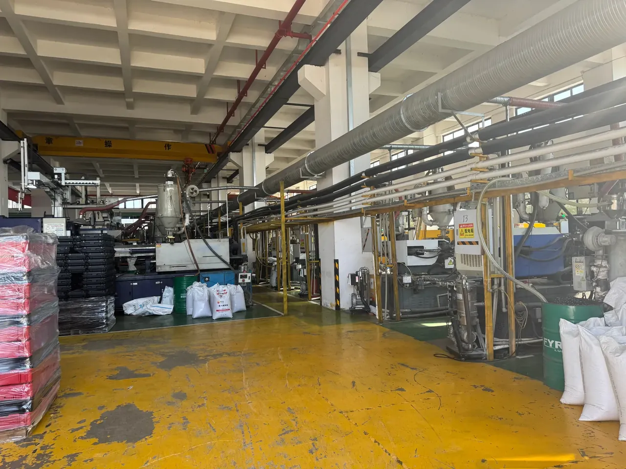
Quick answer: Case Injection Molding Machine sizing starts at the screw: 65 mm at 22:1 gives a 1280 g shot and 386 t of clamp, so a 650 t press runs at 59 percent.
Table of contents
- Case Injection Molding Machine Screw Diameter and Shot Weight
- Case Injection Molding Machine Cooling Circuit Grouping and Flow Split
- Case Injection Molding Machine Take-Out Robot Stroke and Cycle
- Case Injection Molding Machine Clamp Force and Platen Check
- Case Injection Molding Machine Daily Checks and Shutdown Limits
- FAQ
1. Case Injection Molding Machine Screw Diameter and Shot Weight
Order the screw first; tonnage is a consequence. Theoretical shot volume is pi over four, times D squared, times stroke. A 65 mm screw on a 388 mm stroke gives 1290 cm³, quoted at 1.05 g/cm³ for polystyrene as a 1280 g shot. Run PP at 0.905 g/cm³ and the same stroke yields about 1100 g, a gap to plan around.
One 400 by 260 mm shell at 2.2 mm wall weighs 813 g and, with 55 g of runner, fills 79 percent of that 1100 g. A 75 mm screw lifts the shot past 1500 g while the shell still weighs 868 g, so the surplus becomes residence time and PP held longer starts to splay.
| Screw L/D ratio | Part type it suits | Effect on pressure and mixing |
|---|---|---|
| 18:1 | Shallow lids, short flow paths | Lower pressure, short mixing section |
| 20:1 | Standard cases and tote boxes | Medium pressure, fine above 2.4 mm wall |
| 22:1 | Deep cases, engineering shells | Higher pressure, even melt, lighter part |
Bigger is not safer. At 22:1 with a 2.5 compression ratio the melt passes feed, compression and metering over 22 diameters, enough mixing without pushing PP past 260 °C.
2. Case Injection Molding Machine Cooling Circuit Grouping and Flow Split
How the water is grouped decides which face sets first. The base runs hottest, the lid thinnest, so heat flux differs two to three fold, and tying six zones into two loops starves the thick sections.
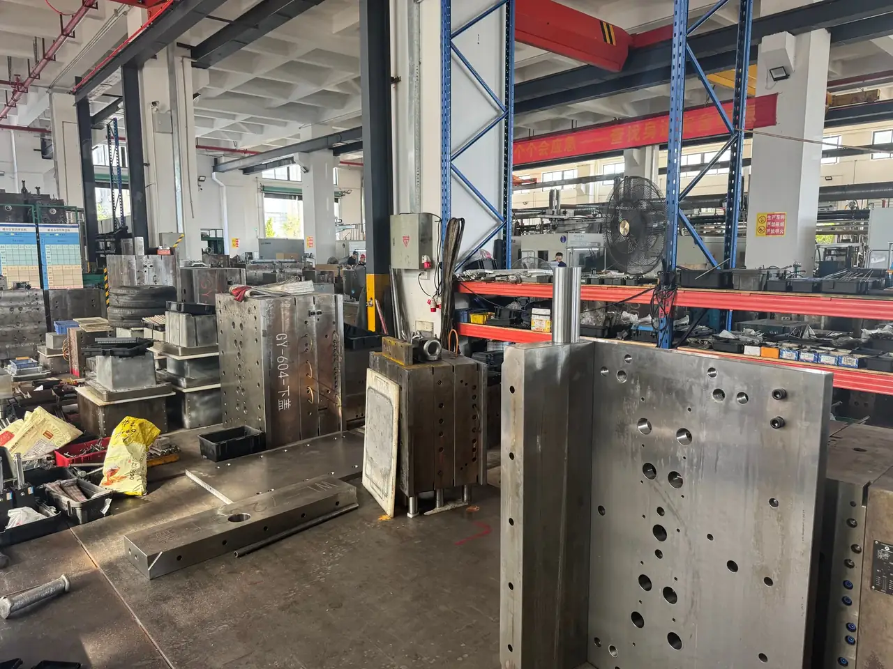
A 10 mm channel at 1.2 m/s carries 5.7 L/min at a Reynolds number of 1.2×10⁴. At 0.6 m/s it drops to 6×10³ and the coefficient, scaling with velocity to the power 0.8, keeps 65 percent.
| Circuit group | Area covered | Flow and temperature target |
|---|---|---|
| Cavity group | Lid skin and long side walls | 18 L/min, rise under 3 °C |
| Core group | Inner base, ribs and bosses | 18 L/min, outlet 2 to 3 °C warmer |
| Slide group | Latch and handle undercuts | 18 L/min, own shut-off valve |
Six groups at 18 L/min total 108 L/min, so the chiller is sized at 120 L/min. Past a 4 °C rise one group is starved: check the valve before the chiller.
3. Case Injection Molding Machine Take-Out Robot Stroke and Cycle
The arm has seconds between platens to lift an 813 g shell. A 1600 mm traverse covers the 810 mm platen plus the drop station outside the clamp; 1200 mm vertical covers the 150 mm depth with 50 mm clearance; 650 mm crosswise pulls clear of the tie bars.
A 42 s cycle splits into 8 s clamp, 2 s injection, 10 s packing, 22 s cooling and 2 s take-out, the last overlapping the second half of opening. A 2.2 mm wall freezes in 9 to 10 s; the rest goes to ribs and bosses, since cooling time rises with the square of thickness.
| Take-out stroke | Machine size it fits | Relationship to cycle |
|---|---|---|
| 1350 mm | Up to 150 t | 0.7 s take-out, 5 s dry cycle |
| 1600 mm | 250 to 450 t | 1.5 s take-out, 9 s dry cycle |
| 1750 mm | 400 to 850 t | 1.5 s take-out, longer traverse |
At 813 g plus 3.2 kg of gripper the load stays under 4.1 kg against an 8 kg rating.
4. Case Injection Molding Machine Clamp Force and Platen Check
Clamp force is projected area times cavity pressure. The shell projects 1040 cm² and the runner 60 cm², so at 300 bar for PP the holding force is 336 t, or 386 t with a 15 percent margin. A 650 t press then runs at 59 percent, the rest loading only the tie bars.

An 810×810 mm platen is checked against the mould outline, not the case outline. A 520 by 380 mm mould leaves 145 mm on each side. Past 690 mm of mould width, the platen less 60 mm of clamping land per edge, the base overhangs and the platen dishes over time.
Here the limit sits on injection, not clamp. Two cavities project 2140 cm² and ask for 654 t, filling the 650 t rating with nothing in hand; at 20 bar of drift, flash opens opposite the gate. A two-cavity shell tool belongs on 800 t and above, with 900 mm class platens.
5. Case Injection Molding Machine Daily Checks and Shutdown Limits
Three blocks, each with a number: screw, water, robot. Screw wear is read at the metering section as the gap between flight OD and barrel bore. It starts at 0.25 mm, and at 0.40 mm the screw has lost 0.15 mm, so plasticising falls and shell weight wanders.
Water is read as flow and rise. Each group carries an inlet rotameter, and under 15 L/min sends the operator to the filter. At a 4 °C rise that group is no longer removing its heat.
The rule at the top of the sheet: screw wear beyond 0.15 mm or a circuit rise beyond 4 °C parks the machine for service. The robot is checked for repeat position, where 5 mm of drift means teaching again.
Conclusion
Inside the selection order for a Case Injection Molding Machine, screw diameter, circuit grouping and take-out stroke stand apart yet pull on each other. A 65 mm screw at 22:1 fixes the shot at 1280 g, six circuits at 18 L/min even out mould temperature, and a 1600 mm stroke matches a 42 s cycle, only after which the 650 t rating and 810×810 mm platen can be checked. When the numbers fail to line up, move the screw first, the water second, the robot last.
Related Reading
- injection capacity and tonnage
- how to select a case molding machine
- case molding machine specifications
- capacity from machine count
Related Products
- 8 Series — Gun Cases; Military Equipment Cases; Camera Equipment Cases; Drone Cases; Watch Cases; Knife Cases; First Aid Cases; Electronics Equipment Cases
- WL8-2812 PP Gun Case — model WL8-2812
- All protective cases and toolboxes: 7 series, 158 models