

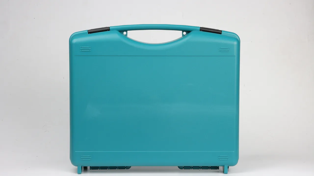
When a boom pump or a truck-mounted pump is stripped for a site transfer, the parts most likely to be written off are not the pump unit itself. They are the few long, heavy lengths of boom pipe and the small, deceptively light-looking distribution valve. On the machine these parts live inside constraints that disappear the moment they are unbolted. Straight pipe sections are held by clamps and carry flow impact through their own stiffness. Once removed, a 3 m straight section becomes a simply supported beam, a bend slowly pushes its ovality outward under gravity, and a wear plate with the smallest rust bloom will never seat evenly again. In transit they are pushed into returnable crates, strapped to pallets, or simply hung on the side of a flatbed in the rain. Drop, side roll, stacking and wetting all happen at once. At reassembly the bore has grown 3 mm, a wear plate edge has been knocked into a notch, and two clamps are missing. Pumping capacity falls, and the cause is written into the packing list four weeks earlier.
JUNZHIJIA holds that boom pipe and distribution valve protection cannot be solved by wrapping everything in one foam blanket. It has to be designed against the failure mechanism of each part: straight pipe is controlled on bore and ovality, bends are controlled on end-face warping, wear plates are controlled on gap and rust, elastomer seals on medium and ageing, clamps on tooth engagement, and pressure pulses on compartment isolation. That is the logic of this article. Each component that most often scrapes in transit is taken apart, described in terms of what it carries in service, how transport destroys it, which structural feature blocks it, and which numbers decide whether it is still serviceable on arrival.
Table of Contents
- Internal Diameter Wear Limit on Straight Boom Pipes
- Aggregate Hardness and Sand Content as Abrasion Drivers
- Ovalisation and End-Face Warping of Bend Sections
- Slurry Trapping and Hardening in Reducer Transition Zones
- Wear Plate Clearance Tolerance and Serial Leakage in Distribution Valves
- S-Valve Reversal Shock and Edge Chipping of Wear Plates
- Compression Set and Medium Attack of Elastomer Seals
- Clamp Tooth Bite, Mismatch and Missing Hardware Counts
- Blocked Pumping Pressure Pulse Paths into Case Structure
- Low-Temperature Grout Expansion and Shell Delamination
- Segment Length Selection, Lift Points and Stack Tier Limits
- Segment Washing, Air Blowing and Dryness Verification
- Arrival Acceptance: Three Data Sheets for Bore, Gap and Kit
- Frequently Asked Questions FAQ
- Conclusion and Related Reading
Internal Diameter Wear Limit on Straight Boom Pipes
Pumping pressure does not wear a pipe through by internal pressure alone. What thins the wall is a sliding abrasive layer: aggregate particles that the grout carries along the bore and that roll against the wall under pressure. The inner surface thins gradually while the outer diameter barely changes, so the pipe still looks the right size even though the usable section has grown. Engineers therefore use internal diameter growth as the primary criterion, because bore directly governs flow velocity, pumping pressure and the probability of a blockage.
| Pipe type | Nominal bore | Wall margin in service | Suggested transport and stock scrap line | Result of exceeding it |
|---|---|---|---|---|
| --- | --- | --- | --- | --- |
| Straight pipe, 133 mm OD class | 125 mm | 6.5 mm and above | Single-side growth above 3.0 mm | Flow accelerates, pressure rises, blockage risk |
| Bend pipe, 133 mm OD class | 125 mm | 8.0 mm and above | Single-side growth above 3.5 mm | Outer curve loses roundness, discharge spreads |
| Reducer, 125 to 100 | 100–125 mm | 5.0 mm and above | Single-side growth above 2.5 mm | Flow regime breaks down at the transition, vortex wear |
| High-pressure delivery pipe | 100–125 mm | 9.0 mm and above | Single-side growth above 4.0 mm | Pressure margin exhausted |
The logic behind these scrap lines is simple: once bore growth exceeds one third of the available wall margin, the section no longer holds a repairable reserve. An oversize pipe fitted to the boom will only amplify the problem on the first blocked stroke. Flow velocity drops in the enlarged section, the grout loses speed and separates, aggregate settles into a hard plug in the invert, pressure climbs quickly and the stroke ends in a blockage shutdown.
The threat to bore in transit is not impact. It is local hard-point loading. If a pipe lies directly on case timber bearers, a bearer edge presses against one point of the inner wall, and transport vibration makes that point press in and out repeatedly under the full pipe weight. The resulting shallow dent becomes a stress concentrator that aggregate enlarges in service. The defence is to make every pipe load up on a continuous facing rather than on a set of edges. The liner is formed as a ring-shaped cradle matched to the pipe diameter, so the whole pipe body sits on it with no unsupported span.

At acceptance, take three readings on every pipe: 100 mm from one end, at the middle, and 100 mm from the other end, using a bore gauge or a roller caliper, and record the maximum. If the spread across the three readings exceeds 0.5 mm, the wall has been crushed or a lump has built up on the inside, and the pipe should be scrapped whole rather than cut down and reused.
Aggregate Hardness and Sand Content as Abrasion Drivers
The wear rate of a boom pipe is not decided by how many months it has been in service. It is dominated by two properties of the concrete itself: aggregate Mohs hardness and sand content. The same pipe can last a year and a half in natural river-sand concrete and exceed its bore limit within three months in a mix built from manufactured sand and crushed chippings.
| Concrete characteristic | Abrasion severity | Relative wall loss rate | Additional transport action required |
|---|---|---|---|
| --- | --- | --- | --- |
| Natural river sand and rounded gravel, 38 percent sand | Low | 1.0 | Standard segmented cushioning is sufficient |
| Manufactured sand with 10 mm crushed stone, 42 percent sand | Medium | 1.8 | Fit end caps, forbid residual sand inside the pipe |
| Manufactured sand with 16 mm crushed rock, 45 percent sand | High | 2.9 | Pipe must be blown clear, end film sealed separately |
| Quartz-rich tailings sand formulation | Very high | 4.5 | One pipe per case, stacking several pipes together prohibited |
This table decides the packing specification. On a high-abrasion mix, the old pipe coming back to the yard is already close to its scrap line. If transport then adds even a shallow dent, the reassembled life collapses. The correct move is to pack returned pipe separately from new pipe and mark the case "returned pipe, measure bore before fitting", so nobody on site bolts a worn section into the boom thinking it is a spare.
Slurry residue takes part in the same mechanism. A low water-to-cement grout forms a hardened shell on the wall, and when the next load arrives that shell is carried along as an extra abrasive surface, effectively roughening the bore on purpose. Cleaning is therefore not a housekeeping requirement but a wear control requirement. The criterion for residue is simple: after drying, a float grout layer comes off with a wire brush, while a layer that will not brush off, that sounds dull when tapped and that shows a clear delamination outline has to be removed mechanically. Both go, and the pipe is then blown clear.
Ovalisation and End-Face Warping of Bend Sections
Bends are the most difficult members of the boom pipe family. In service they are squeezed between two clamps into a specific curvature, and that curvature is what offsets the centrifugal separation the flow creates at the bend. Once the end flanges or threaded ports are released, the bend deforms slowly under its own weight in the radial direction, and the two ports stop being round.
For a 90 degree bend there are two driving mechanisms in transit: the continuous bending moment the pipe's own weight produces in the plane of the bend, and the low-cycle fatigue that repeated transport vibration builds up. Ovality can be measured directly with calipers at each port, or checked by laying the bend flat and passing a plug gauge of the nominal diameter at each end.
| Bend specification | Permitted ovality after transport | Measurement method | Action when out of tolerance |
|---|---|---|---|
| --- | --- | --- | --- |
| DN100 90 degree short bend | Major-minor axis difference 1.2 mm maximum | Two-way caliper at the port, take the largest | Re-round and reuse |
| DN125 90 degree short bend | Major-minor axis difference 1.5 mm maximum | Same method | Re-round and reuse |
| Long-radius R bend | Major-minor axis difference 2.0 mm maximum | Same method | Re-round and re-verify |
| Tapered bend | No twist permitted, angular deviation 1.5 degrees maximum | Compare against a locating template | Not reusable |
Packing a bend correctly requires the bend to lie on its side with the plane of curvature parallel to the case floor. Laid flat like a steel section, its own weight presses the opening out of shape. Stood upright, gravity pulls the crown down along the span and the shape changes permanently. The answer is a cradle formed to the bend's own radius, with the liner following the outer arc and slings passing around both sides without any force pushing inward. Sling pre-tension only has to stop the part moving in transit. Pulling it tight marks the bend, and those marks are exactly where the flow starts to split once pumping resumes.
End-face protection matters just as much. A bend ends in a flange, a tapered thread or a clamp fitting, and whichever it is, the end face is the most accurately machined surface on the part and the easiest to chip in transit. Once chipped, the joint loses its seal and the line weeps grout or even parts. Fit an end cap on every port, or wrap it in a protective film, using an interference-fit plastic plug matched to the bore. A generic cap that simply drops inside is worse than nothing: it does not hold, slides along the bore during transit and hammers the wall from the inside.
Slurry Trapping and Hardening in Reducer Transition Zones
A reducer joins two different pipe diameters in the delivery line. Its bore steps abruptly from one size to another, producing either a sudden expansion or a sudden contraction, and it is the least stable flow section in the whole line. It is also where grout hides.
The mechanism is direct. Between the main streamline and the wall at the diameter change there is a separated boundary region with low velocity and low shear. Fine sand and cement particles are thrown out of the main stream and deposit against the wall. After the pump stops, that deposit begins to hydrate and set within minutes, forming a hard crust on the conical face. The crust does two kinds of damage. On the next start it is carried downstream as a fresh wear source, and it locally reduces the effective section, so pressure rises at that point during pumping.
The reducer liner therefore has to be closer to the pipe than a straight pipe liner needs to be. A straight pipe tolerates a gap between body and liner because the diameter is constant. If a reducer liner leaves a cavity, grout can shift the liner in transit like a piston, the body then works against the liner, and the contact concentrates on the two edges of the transition, which happen to be the thinnest place there is.
Three specific measures apply:
- Give the transition section its own cavity, with a formed liner matching the cone curvature so the body is never unsupported on the small-diameter side.
- Limit axial movement of the liner at the transition with a shoulder that holds the body to under 2 mm of float along the axis.
- Support the bolt-hole region on the reinforced flange at discrete points, so lifting and slinging cannot pull the flange holes open.
At acceptance, run a dedicated ball or mandrel check on every reducer. Pass a plug gauge sized 2 mm under the bore on the small side; if it does not pass cleanly, hardened residue is still hanging in the transition.
Wear Plate Clearance Tolerance and Serial Leakage in Distribution Valves
A distribution valve, most often an S-valve but also gate or ball types, is the small component that switches flow from the pumping cylinder into the line, or between two lines. Its working element is a pair of wear plates that close against each other to form a seal. Concrete under high pressure is forced into that gap, and sealing is achieved by the wear-resistant layer in the plate combined with lubrication from the grout itself.
Once a wear plate goes out of tolerance the result is cross-leakage and backflow. Material moves from the high-pressure side to the low-pressure side and pumping efficiency falls. At the same time backflow on the low-pressure side grabs the plates at the moment they close, so the valve binds and stalls during reversal. This is one of the sources of the field complaint commonly called blocked pumping, and unlike a line blockage it has nothing to do with pumping pressure. It is created purely by the sealing gap.
| Inspection item | Standard value | Measurement method | Consequence of exceeding it |
|---|---|---|---|
| --- | --- | --- | --- |
| Wear plate seating flatness | 0.05 mm maximum | Straight edge and feeler gauge | Local wear first, contact band narrows |
| Single-side gap between plates | 0.10 to 0.25 mm | Three-point feeler method, top, middle, bottom | Too large leaks, too small binds |
| Edge chipping | Not permitted | Visual and tactile | Chip becomes a stress raiser and crack origin |
| Plate surface roughness | Ra 1.6 to 3.2 | Roughness tester | Coarse surface scours and loses the seal |
| Rust on the sealing face | Not permitted | Visual | Rust gives uneven contact and spreads corrosion |
Note the wording "single-side gap". The gap between two plates is measured on one side. A single-side figure of 0.20 mm means a 0.40 mm leakage passage once both sides are counted, and that is a substantial flow path at 10 MPa pumping pressure. Many sites confuse the two-sided figure with the single-side figure, assemble to what they believe is 0.2 mm, and end up with 0.1 mm per side, at which point the plate binds on reversal.
Wear plate protection in transit has to be independent of the valve body. The normal method is to pack the plates for rust separately: once the plates pass inspection they receive a thin coat of protective grease or a wrapping of corrosion-inhibiting paper, then go into an individual bag in the void of the compartment holding the valve body, with the assembly sequence written on the bag. Bare plate faces must never touch the case liner directly. Liner surfaces are closed-cell and still shed extremely fine particles, and any particle that reaches the sealing face becomes a leak path.
S-Valve Reversal Shock and Edge Chipping of Wear Plates
An S-valve is driven by two hydraulic cylinders and swings above the outlet of the pumping cylinder. Every reversal takes the valve from one sealing position to another, and the plate edge goes through a detach and reseat cycle in a very short time. That cycle is not static. It has two sources.
The first source is the kinetic effect of hydraulic reversal. The cylinder accelerates the valve, decelerates it and stops it on arrival, so a heavier valve body on a shorter stroke with a higher flow rate produces a stronger inertial shock. Reversing while pumping at high pressure superimposes the two. The second source is the dynamic pressure of the material itself, because the concrete leaving the pumping cylinder arrives at the valve with real velocity and the plate edge is the face that receives it.
Superimposed, these two effects chip the plate edge. Once a chip exists it develops further, because the sharp arris keeps breaking away in later reversals, the notch grows, and the sealing band narrows. When the notch reaches the point where no continuous sealing band can form, the swinging plate strikes the seat directly, the plate fractures, and fragments enter the pumping cylinder, where they either block the outlet or damage the piston seal.
| Reversal condition | Shock severity | Typical damage location | Scrap basis |
|---|---|---|---|
| --- | --- | --- | --- |
| Low pressure below 3 MPa, slow reversal | Light | Minor bright spots on the plate edge | Not scrap, polish and reuse |
| High pressure 8 to 12 MPa, normal reversal | Medium | Pitting on the material-facing edge | Pit depth above 0.1 mm is scrap |
| High pressure with reversal after a blockage | Severe | Edge chip of 1 to 2 mm | Any chip is scrap |
| Abnormal reversal frequency from repeated line blockage | Severe | Chained chipping and plate distortion | Scrap |
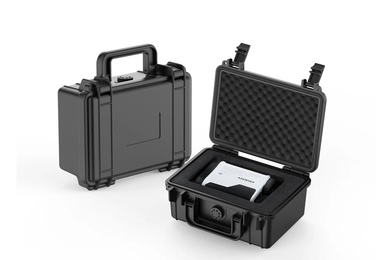
The packing requirement is that the valve body receives no external load in transit. The centre of gravity of an S-valve sits on the plate side, so a point-support arrangement allows the plate to swing about that point whenever the case is jolted, and the plate edge sits at the longest moment arm. The valve therefore needs three-sided constraint: the base face seated, both flanks in contact, and the rear face blocked, so the plate cannot displace in any transport attitude. The two hydraulic cylinder rods are separately limited by blocks fixed to the case. Cylinders must not be free to extend inside the case, because each stroke end drives the plate to an angle and releases it, which reproduces the shock of a real reversal several times inside a closed box.
Compression Set and Medium Attack of Elastomer Seals
The sealing system of a distribution valve consists of the main seal, which may be the wear-resistant layer in the plate itself or a rubber strip, plus O-rings, hydraulic cylinder seals and wiper rings. The elastomer parts are the ones most often overlooked and the ones that most affect reassembly.
Concrete attacks elastomer by three routes. The first is grout penetration and abrasion: fine sand and cement particles form a dry friction layer on the compressed sealing face, and every reciprocating stroke grinds that layer into the rubber as an abrasive. The second is alkali attack. Cement grout routinely sits above pH 12, while most elastomers have limited alkali resistance, so prolonged contact softens the surface and drops the hardness. The third is ageing. Elastomers held under compression, or exposed to grease and hydraulic oil, take a compression set and swell.
| Seal type | Primary failure mode | Transport factor that accelerates it | Packing requirement |
|---|---|---|---|
| --- | --- | --- | --- |
| Nitrile O-ring | Compression set and swelling | Contact with hydraulic oil and grease, temperature cycling | Bagged separately, kept away from solvents in the same case |
| Plate rubber strip | Abrasive wear, alkali softening | Contact with liner particles | Individual corrosion-protective bag plus a rigid separator |
| Hydraulic cylinder seal | Compression set | Long-term pre-compression | Must not be pre-compressed before assembly |
| Wiper ring | Hardening, edge tearing | Deformation under compression | Suspended or in its own recess |
| Inert sealing gasket | Compression distortion | Temperature cycling | Stored separately with thickness marked |
Compression set has one deceptive feature. If a seal ships already compressed, it has lost rebound reserve before it ever reaches the machine. It passes the bench check on installation and then starts weeping oil after a few dozen operating hours. Seals must therefore never be compressed in the packing state. Do not pack an O-ring pressed into its plate recess; fix each seal in its own recess following the assembly sequence instead.
Seal count is an acceptance item in its own right. The shipment must itemise how many plates, main seals, O-rings and wiper rings it contains, and the site counts what actually arrives. Shortages are rarely caused by careless packing. They come from the kit relationship not being written down. One plate type needs two plates per assembly, and each plate needs two O-rings. A manifest that says "wear plate, 1 off" guarantees a shortage on site. Clamp kits follow the same logic, as described below.
Clamp Tooth Bite, Mismatch and Missing Hardware Counts
Boom pipe joints rely on clamps to transfer axial thrust. One clamp is a band, either U-shaped or circular steel, two lugs, a fastener set of twin bolts and nuts, and optionally a sealing strip. It presses two pipe ends together on a taper or a flat face, and the thrust passes by friction and taper self-locking while the strip seals.
Two problems dominate: tooth engagement and mismatched, missing hardware. The tooth on the inner face of the band bites the pipe wall, and it is one of the most worn surfaces in transit. Once the teeth are polished flat, the band relies on smooth friction, the coefficient drops, and axial thrust transfer drops with it. Pumping pressure then makes the clamp slip, the ends rotate against the taper, and the sealing face is dragged into scratches that eventually leak grout. When no tooth profile can be felt, the clamp is scrap. Compensating by tightening harder is not a repair.
Matching is the second issue. Clamps are not interchangeable. Ear spacing and bolt length differ by pipe diameter, maker and series. Mixed hardware gives bolts that will not line up, a forced diagonal pull, and a band twisted as it tightens. A twisted band relaxes under transit vibration and arrives on site out of shape.
| Check item | Acceptance criterion | Method |
|---|---|---|
| --- | --- | --- |
| Band tooth profile | Continuous crests, no polished length | Visual and touch, tooth feel must be obvious |
| Band inner face free of rust | No pitting | Visual |
| Lug to band perpendicularity | 0.5 mm maximum | Straight edge and feeler gauge |
| Bolts straight and free of damaged threads | Full thread length intact | Visual and thread gauge |
| Ear spacing matched to the pipe end | Exact correspondence | Trial fit |
| Sealing strip | Present, no hardening cracks | Visual and bending |
| Quantity per set | Complete against the manifest | Count |
Count by the set. State on the bag how many pieces constitute one set, for example band by one, lugs by two, bolts by two, nuts by two, strip by one. Also list how many sets are in the compartment and which pipe sections they belong to.
Blocked Pumping Pressure Pulse Paths into Case Structure
Pumping is a cyclic load. Concrete advances as a plug or non-Newtonian flow, and each cylinder stroke produces a pressure wave that travels along the line, reflects at bends and the far end, and superimposes, so peaks sit far above the mean. Three paths carry that pulse into the packing.
The first is direct: any residual blockage left in the case, such as a clearing sponge, a plug or a temporary plate, has the pulse acting on it, and it becomes a piston driven against the case wall. The second is structural: the pipe acts as a beam, the pulse creates reaction at its restraint, and the reaction passes through the liner into the case, then to the pallet and the vehicle. The third is contact: the pulse also acts on residue inside the pipe, and compressed residue squeezes outward and pushes the pipe radially out against the liner.
The third path is the one most often overlooked. Any residue turns the pipe from a protected item into a pressure source. Washing pipes to a blown-clean state is therefore a safety requirement, not a habit.
| Load source | Peak character | Packing response | Verification method |
|---|---|---|---|
| --- | --- | --- | --- |
| Cylinder stroke pulse | Several hertz to above ten hertz | Segmented circumferential support | Measure bore after 24 hours at rest, fully loaded |
| Blocked pumping, plugged line | Single peak up to two to three times mean pressure | Separate compartments with expansion volume | Confirm no residual plug in the case |
| Water hammer at stop | Short steep rise | Buffer thickness margin | Measure deflection under full load |
| Residue expansion | Grows with temperature and age | Leave free cavity volume | Mandatory on winter long haul |
A static rest check is worth isolating. After packing, leave the case at ambient temperature for 24 hours and re-measure the bore. If the bore keeps growing during that period, a growing load exists inside, usually expanding residue or an over-tight liner, and this test finds the problem a week earlier instead of on site.
Low-Temperature Grout Expansion and Shell Delamination
Winter long haul, and any movement from north to south, carries one dominant risk: expansion of residual grout as it freezes. Water in concrete expands about 9 percent when it freezes. If 3 kg of residue holds 0.5 kg of water, the extra volume approaches 45 ml. That volume has to go somewhere. The pipe is closed, so it pushes outward, and if the liner already grips the pipe, the expansion allowance is gone and 45 ml becomes internal pressure, shown as wall bulge, leakage at a threaded end and deeper liner impressions.
The opposite mechanism is delamination. Water-rich residue hydrates slowly in transit and forms a hardened shell. The shell does not attack the pipe by itself, but its adhesion grows with age and release happens at vibration load points. When a shell leaves the wall as a whole piece it takes the pipe surface with it. This is transport wear: the pipe looks sound on arrival and fails the bore limit on the first stroke after refitting.
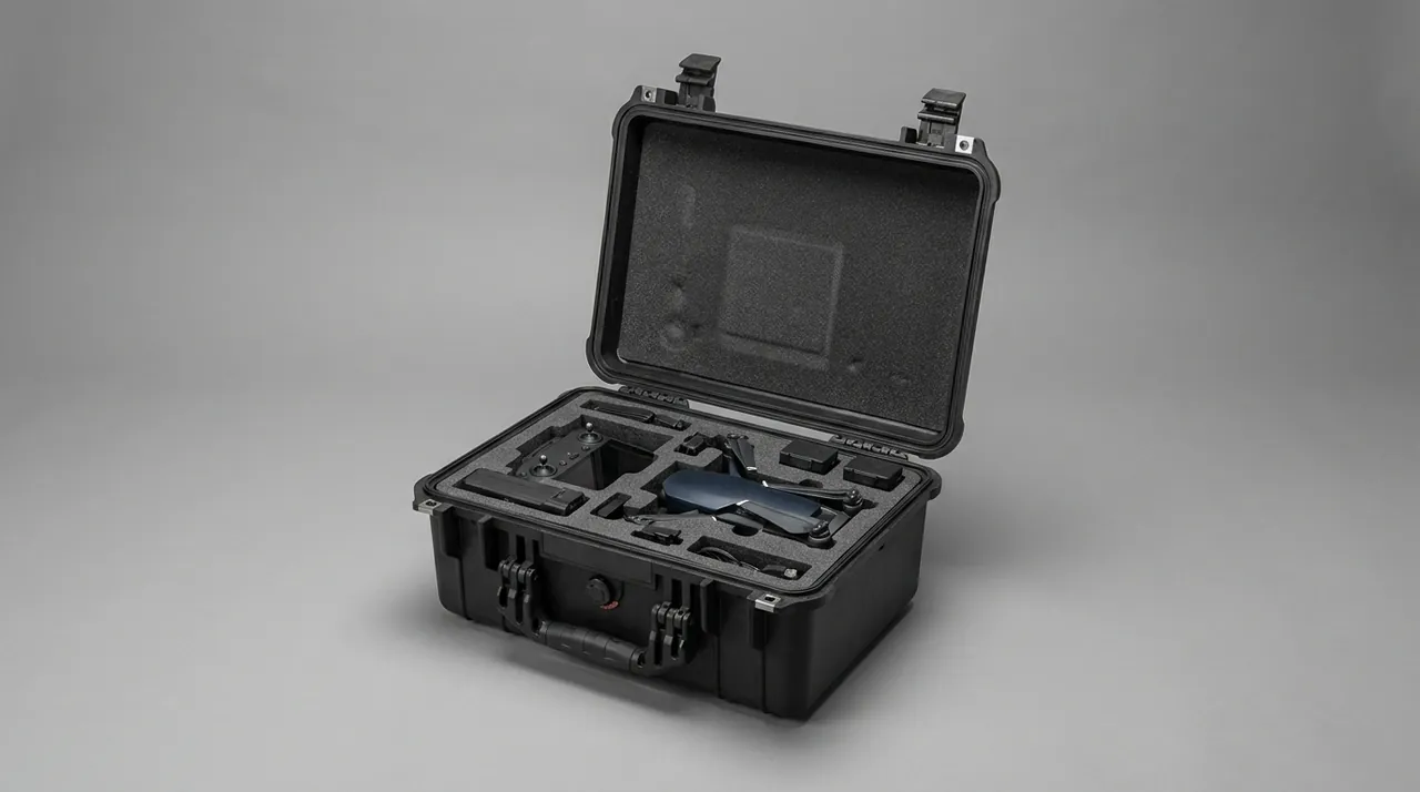
Two families of measure apply. Physical isolation means washing and blowing before packing, then sealing each port with film or a plug so case humidity cannot condense inside again. Climate control means desiccant and a humidity indicator card in the cavity on winter sea freight or winter road haul. The desiccant does not dry the pipe, which is already dry. It controls condensation in the case so no film reforms at the sealed port.
| Scenario | Residue risk | Freeze risk | Mandatory action |
|---|---|---|---|
| --- | --- | --- | --- |
| Fit and go on site, under 12 hours | High | Low | Blow clean, seal the port |
| Short transfer, 1 to 3 days | Medium | Medium | Blow clean plus desiccant and indicator card |
| Sea freight over 15 days | Low | High | Full wash, double sealing, desiccant |
| Winter road haul | Medium | High | Prefer heated transport, otherwise thicken the insulated cavity |
| Summer road haul | Medium | Low | Watch for desiccant baked out by high temperature |
Cleaning has its own section, and the fifth failure mode, dryness confirmation, is set out there. The two must be read together.
Segment Length Selection, Lift Points and Stack Tier Limits
A boom pipe is long, heavy, hollow and easy to distort. A full-length pipe in one case leaves the middle unsupported, will not fit through a standard door opening or into a cargo bed, and does not stack squarely. Too rigid and the case cracks in transit. The first packing decision is therefore segment length.
Segments are decided by what passes through a standard doorway and cargo bed and can be handled by two people, not by the original pipe length. Common choices are 1.0 m, 1.2 m and 1.5 m. There are two ways to deal with the cut. Either a flange is fitted to the cut end and short flanges bolt the sections back together on site, or the sections ship separately and are rejoined by welding or threading with the original fittings. The first restores original length accuracy, the second costs less but consumes site labour. State which method applies on the packing label.
| Segment length | Mass per segment at DN125 | Case type | Stack tiers | Note |
|---|---|---|---|---|
| --- | --- | --- | --- | --- |
| 1.5 m | about 22 kg | Medium single cavity | 2 | Two people can handle it |
| 1.2 m | about 18 kg | Medium single cavity | 3 | Best all-round choice |
| 1.0 m | about 15 kg | Compact case | 4 | More clamps needed, matching gets complex |
| Full length 3.0 m | about 55 kg | Special long case | 1 | Intermediate support is mandatory |
Lifting points are a separate problem for hollow parts. A sling applies a local circumferential force that spreads from the lift point in both directions. Too few points and the body sags on lift, pressing a dent into the bottom liner. Too many and the slings cinch the body into a fish-belly shape that cannot be unloaded. Three-point or four-point lifting is normal, and a wide soft pad must sit between sling and pipe, at least 50 mm wide and extending at least 150 mm beyond each side of the lift point, turning a point load into a distributed load.
Stack tiers are decided by whether the pipe in the bottom case keeps its bore. Weight from the case above passes through its lid and liner onto the pipe below as a radial line load on a surface that barely matches a pipe, and that is what flattens the bore locally. The same total mass split into more, lighter cases can carry more tiers at lower collapse risk, which is an economic trade-off often missed: twelve pipes in one case means one tier, while two cases of six allow three tiers.
| Stack tiers | Load from case above, estimated | Liner compression at pipe crown | Verdict |
|---|---|---|---|
| --- | --- | --- | --- |
| 1 | 0 | None | Reasonable for a heavy single case |
| 2 | about 1.2 kPa | 3 to 5 percent | Medium case stiffness is enough |
| 3 | about 2.4 kPa | 8 to 12 percent | Liner and lid need reinforcement |
| 4 and above | above 3.6 kPa | above 15 percent | Compression may exceed limits, not advised |
Mark the maximum stack tier, unit mass, centre of gravity and lift points on every case. Site teams stack beyond limits to save floor space, and the only purpose of the mark is to stop them before they do.
Segment Washing, Air Blowing and Dryness Verification
Several sections have already required pipes to be blown clean and free of residue. This section fixes the judgement. If it is done badly, every freeze, delamination and internal pressure measure above fails.
Wash water first and air second. Water carries the bulk of the grout away; air only moves powder that has already loosened. Blowing first spreads fine dry powder onto the wall, and the water then turns that powder back into grout. The workable sequence is a high-volume water flush, mechanical brushing of the remaining shell, a second water flush, compressed air blow-down, natural draining, then re-inspection.
| Verification method | How it is done | Acceptance criterion | Where it applies |
|---|---|---|---|
| --- | --- | --- | --- |
| Borescope visual | Insert an endoscope and inspect the full wall | Continuous wall, no deposit, no shell, no water film reflection | Straight pipe, bore DN80 and above |
| Dry cloth drag | Pull a dry white cloth strip through the bore | Strip comes out dry with no grey-white residue | Any diameter, best value for money |
| Weighing | Compare mass before and after washing | Residual mass 0.2 percent of pipe mass or less | Batch quantity acceptance |
| Hand feel | No slipperiness, no adhering particles | Qualitative | Quick spot check |
The dry cloth drag is the most useful field method. A dry white strip is pulled through the bore; if it emerges wet or carries grey-white traces, water or fine grout remains and the pipe must be redone. Many teams stop at blowing with air and skip the re-inspection, because the pipe looks dry afterwards. The problem is that air moves the core flow only, and the water film and wall-clinging grout in the boundary layer never move at all.
A failed result means washing again, not blowing longer. Use a nylon or wire brush with water for a hardened shell, and a wire brush only where the wall is thicker than 6 mm. On thin wall pipe use a nylon brush or a high-pressure water lance, because scratching the bore creates pits, and a pit is the next aggregate wear site. Adjacent pipeline pumping and dosing assemblies face a comparable mix of pressure and abrasion, and the packing logic for pump and valve parts cases applies the same split between sealing faces and flow-path wear.
Seal immediately after washing. Packing first and sealing afterwards is not acceptable, because sealing has to happen while the pipe is still warm and wet to be effective. Once the port film is on, the bore and the case interior are no longer connected, so condensation in transit forms on the outside of the film where desiccant can take it. With an open bore, water vapour moves in and out and eventually condenses as droplets in the lowest section of a pipe.
Arrival Acceptance: Three Data Sheets for Bore, Gap and Kit
However correct the packing, arrival inspection holds the final decision. Acceptance for concrete pumping parts should land on three data sheets, each with defined measuring points, tools and criteria, so that acceptance never rests on looking acceptable.
The first sheet is the boom pipe bore sheet. Every pipe is measured at three points, 100 mm from one end, at mid length and 100 mm from the other end, with a bore gauge or roller caliper, and the maximum reading is recorded. Record the spread across the three readings at the same time, and treat a spread above 0.5 mm as crush damage scrapping the whole pipe.
The second sheet is the distribution valve gap sheet, recording the single-side gap at three points, seating flatness, chipping and its depth, rust on the face, and sampled roughness. Also record the sealing condition at the moment of opening, meaning whether the corrosion-protective bag was intact and whether an oil film was visible on the plate. That opening state is often left off the form, yet it is the only site evidence available when a dispute follows.
The third sheet is the accessory kit sheet, counting clamps by the set and recording which pipe section each set serves, seals by type and quantity, bolts and nuts, end caps and plugs, and desiccant, then reconciling the case manifest against the accompanying documents.
| Acceptance sheet | Mandatory readings | Tools | Direct scrap line |
|---|---|---|---|
| --- | --- | --- | --- |
| Boom pipe bore sheet | Three readings plus spread | Bore gauge or roller caliper | Single-side growth past the scrap line, or spread above 0.5 mm |
| Distribution valve gap sheet | Single-side gap, flatness, chipping, rust | Feeler gauge, straight edge, roughness tester | Any chip, any rust, gap outside range |
| Accessory kit sheet | Clamp sets, seals, fasteners | Count | Any shortage is a failure and must be recorded |
Two companion philosophies appear elsewhere on this site. Metering and mixing parts in concrete batching cases and hydraulic pumps and travel motors in construction machinery part cases both arrive on the same logic, a data sheet, photographs and a signature, with none of the three optional.
Two things still follow arrival rather than ending with the open lid. First, restore environmental balance. A case wintered outdoors and opened indoors can sit well below the outdoor temperature, and sealing faces and wear plates contract when cold, so immediate assembly gives a mismatch. Let the case stand indoors until temperature equalises. Second, check the first assembly. After fitting the distribution valve, cycle it manually at low pressure, no more than 1 MPa, and confirm free movement, even contact and complete plate seating before any high pressure is applied.
Frequently Asked Questions FAQ
Q: A boom pipe arrives with the bore out of tolerance. Is that transport damage or service wear?
A: The distribution of the oversize bore decides it. Growth spread evenly over the full length, with a large difference between inner and outer diameter, is abrasive wear from service and has nothing to do with transport. Growth confined to a few positions, usually corresponding to case timber edges, liner seams or stacking contact points, is transport crushing. One more practical test: measure the whole length, and if the oversize points repeat at case changes and between stacked cases, transport carries most of the weight. Mixed cases are the hardest, worn and dented together, and the pipe should then be judged on the worse side. Do not measure only three points on arrival. For straight pipe over 2 m, take a reading every 500 mm along the length. That data costs almost nothing and removes the far larger cost of dismantling the boom within three days of startup. The reading grid also gives the receiving yard a quick accept or reject call, so a genuinely worn pipe is not bolted into a structure that will fail its pressure test.
Q: Rust spots are found on wear plate sealing faces after opening the bag. Can the valve still be assembled?
A: No. An even oxide film across the sealing face is acceptable; rust spots are not. A rust spot is an oxidation product embedded in the surface and standing proud, so it carries the entire contact pressure while the surrounding face loses contact. The sealing band shrinks from full width to a few millimetres, the working area collapses, and a crack starts at the spot within a few tens of thousands of cycles. More importantly, the site cannot restore the sealing condition. Polishing removes material that cannot be replaced, and pickling changes the roughness so the first wear stage arrives sooner. Photograph the plate, measure the gap, record both, then treat it as a replacement and fit a new plate in the assembly sequence. If the kit carries no spare plate, the whole machine waits for the part, and that lost production beats the cost of one extra anti-rust step before packing by a wide margin.
Q: A clamp will not tighten fully onto the pipe. Does that mean the wrong size was supplied?
A: Yes. Ear spacing, bolt length and band width are all set by the pipe end size, and mixing them produces a bolt that will not run, a forced diagonal pull and a twisted band. Check ear spacing and effective bolt length against the nominal figures for that pipe end, and reject the set if either disagrees. One case is easy to misread: the bolt reaches full torque while the band is already twisted at the ears. That band is carrying torsion instead of circumferential force, so the clamp force never builds and it slips during pumping. Replace the set rather than fitting a longer bolt. A bolt that sticks out beyond its nut has a free end that vibrates, lets the band shift, and shakes the teeth out of the band. A correctly sized set seats with the band flat and the ears parallel, and that flat seat is what lets the clamp hold circumferential force without relying on the bolt to do the work of the band.
Q: Pipe interiors have been flushed with water for a long time. Is a dry cloth drag check still necessary?
A: Yes. Water removes bulk grout but not the film in the wall boundary layer or the fine grout clinging to the wall. Those adhere to the surface and need mechanical or aerodynamic shear to leave. The quantity is small, yet its effect in transit is disproportionate. A dried grout shell half a millimetre thick goes through repeated wet and dry cycles on a long haul and ends up as hard as mortar. Once that shell is part of the bore it has effectively roughened the surface. The drag check is the only direct way to confirm the layer has gone. Cloth strips can be reused, but use a fresh one per pipe so the previous residue does not contaminate the verdict. A passing strip emerges dry and white, or carrying nothing beyond the natural colour of the cloth. Where a pipe is destined for a site with no wash bay, the drag check is the only evidence the bore left the sender clean, so the strip is kept with the packing record as proof.
Q: Do boom pipes need extra insulation for winter long-haul transport?
A: What is needed is condensation control, not insulation as such. Freezing expansion of residual grout is avoidable: no water inside means no ice. The real winter risks are condensation from case humidity at the sealed port, and condensation on the pipe exterior that then freezes on the case below. Three layers address them. After washing and blowing, seal the port immediately to isolate bore air from case air. Place desiccant in the cavity to hold relative humidity below the dew point. Select shell and liner materials with high closed-cell content that do not absorb moisture, and leave space for the desiccant to be positioned. During loading keep pipe clear of the metal side walls, which are the coldest condensation surfaces, and a dry separation layer is enough. The point is that the pipe does not need to be warm, only dry; once relative humidity is held below the dew point the freeze risk disappears regardless of outside temperature, and insulation alone would not have achieved that.
Q: Once boom pipes are cut into segments, can assembly accuracy still be guaranteed on site?
A: It depends on the joint method. A flanged segment joint takes its accuracy from flange face machining and end protection. Provided the flange faces are not chipped in transit and the sealing faces are not scratched, bolting them back with same-specification fasteners gives better bore continuity than a welded original joint, because flange faces are machined more accurately than a weld. Welding or threading the sections back on site costs less and consumes more labour, and the weld bead protrudes inside the bore as a hard obstruction that scatters flow, traps material and becomes a wear site. Choose according to site welding capability and the maintenance window available. Note also that changing the segment plan changes the joint count, and the joint count sets the number of clamp sets that must ship. Similar sectioning and support logic for long slender items appears in dredging pump cases. The same principle, that cutting changes joint count and therefore part count, is why the segment plan is fixed before packing and not revised at the depot.
Q: Can the distribution valve and boom pipes share one case without cross contamination?
A: They will contaminate each other unless two kinds are prevented. Particle contamination comes first. A hard particle on a plate sealing face or a valve seat damages the surface on the first cycle after assembly. Pack plates in their own sealed sleeve, place a rigid separator between them and the pipes, and never share one foam cavity. Chemical contamination comes second. Rubber seals must not share a case with solvent-based rust inhibitors or adhesives, because vapour is absorbed into the elastomer and causes swelling and hardness change, which appears not at packing but as an oil leak after a period of running. Bag and seal the seals and keep them away from any solvent-based rust material. Divide the case into three zones, precision seals, hard pipe parts and loose accessories, with a separator and an independent buffer layer at each boundary. That three-zone split is also the cheapest way to keep the sealing faces untouched during loading, because each zone is opened only when its own parts are needed.
Q: The outer packaging is already waterproof. Is moisture protection still needed inside?
A: Yes, because the two address different mechanisms. External waterproofing handles liquid water, driven rain and seam seepage. Internal moisture control handles water that is not liquid: condensation inside the shell caused by day-night temperature swing, vapour released by residual grout, and humidity carried in with the parts. Pipe and valve are far more sensitive to the second group than the first. Once a pipe wall rusts, the scrap line is close; once a plate carries a rust spot, the whole plate is replaced. External waterproofing therefore cannot replace desiccant and a humidity indicator card. The sensible arrangement lets the shell carry rain and mechanical protection while the internal cavity carries condensation and humidity control, each independently verifiable. Abrasive and consumable items such as cutting discs and sanding sheets have a comparable need for dry, individually separated packing, as covered in abrasive consumable cases.
Conclusion and Related Reading
Transport protection for boom pipe and distribution valve intercepts three in-service failure mechanisms before delivery: bore and gap by structure and cushioning, residue by washing and sealing, corrosion by independent sealing and humidity control. JUNZHIJIA specifies segment length, liner combination and compartment layout against pumping pressure, haul distance and climate, with custom moulding, OEM/ODM and case documents from Kexin New Materials (Guangdong) Co., Ltd.
Related Reading