

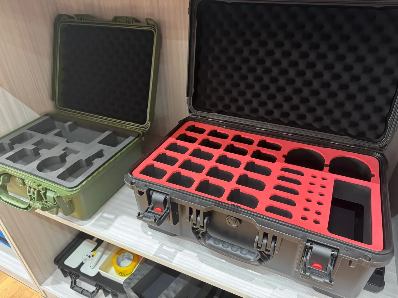
Quick answer: Custom Foam Inserts for Instrument Cases move from scan to die edge in six steps, holding ±0.5 mm cavities on a 0.3 mm allowance.
Table of contents
- The drawing intake for custom foam inserts
- Three conversions from scan to die outline
- Thickness budgeting in the press and glue line
- Cavity tolerance and die-edge allowance
- Keeping a batch consistent by retention samples
- FAQ
1. The drawing intake for custom foam inserts
A foam order arrives as a drawing, and the first gate is not the cutting bed but whether that drawing can be read by a die. Three questions settle it: is there a 3D model, how many pockets are wanted, and does the lid need an egg-crate layer. Without answers there is nothing to nest, so Custom Foam Inserts for Instrument Cases always begin with an outline sheet, a loading sketch and a pocket list.
The outline sheet runs to one decimal place in millimetres, and the loading sketch marks which face points up. For a handheld unit of 210×160×85 mm with connectors on the right, the pocket opens upward and leaves 15 mm clear on that side. A pocket list usually carries 3–6 positions with 8 mm of foam wall between them, since anything thinner collapses at the die edge.
Once the pocket count is fixed the outline follows, and the outline decides the cavity of the case. A case with 470×370×170 mm inside takes a 465×365 mm insert at 60 mm thick, with 2.5 mm of clearance per side. When the documents disagree the drawing is corrected first, since one trial costs a whole steel rule plate.
2. Three conversions from scan to die outline
A Custom Foam Inserts for Instrument Cases job runs through three conversions from a physical unit to a die outline, each adding its own offset. Scanning records the surface to ±0.05 mm; modelling adds 0.25 mm over that cloud as loading clearance; nesting adds 0.3 mm at the die edge for rebound and kerf. The finished outline sits about 0.55 mm larger than the instrument, which is what makes the fit neither loose nor binding.
A prototype and a production shell often differ by 0.3–0.8 mm, and scanning exists to absorb that. Cutting to a prototype leaves pockets that no longer line up with production shells, so a second scan follows the signed first-off sample.
| Conversion step | Input | Output | Offset carried |
|---|---|---|---|
| Point cloud scan | First-off unit | Surface cloud | ±0.05 mm |
| Modelling offset | Point cloud | Pocket surface | +0.25 mm |
| Die-edge allowance | Pocket surface | Die outline | +0.30 mm |
All three offsets point outward; an inward step cannot be shimmed and forces a recut.
3. Thickness budgeting in the press and glue line
A 60 mm block is laminated, not foamed in one shot. The usual build is 20 mm EVA at the base, 15 mm EVA on the walls and 20 mm egg-crate in the lid, bonded under heat and settled to 55–58 mm after pressing; a 2–5 mm loss against nominal is normal consolidation. Custom Foam Inserts for Instrument Cases are budgeted at this step, and case depth is adjusted afterwards.
Pressing runs at 130 ℃ for 45 s with a 0.1 mm glue line. Too cool and the adhesive never cures, leaving white strings when the block is peeled; too long and the foam skins over and loses a step of rebound. A bonded block rests 24 h at 23 ℃ before cutting.
| Material | Density | Common thickness | Role in the build |
|---|---|---|---|
| EVA | 70 kg/m³ | 15 / 20 mm | Base shaping and wall definition |
| EPE | 30 kg/m³ | 20 / 30 mm | Lid egg-crate and light dividers |
| XPE | 45 kg/m³ | 10 mm | Thin partitions and facing sheets |
EVA at 70 kg/m³ holds compression set under 10% at 23 ℃ over 22 h, while EPE at 30 kg/m³ flattens quickly and belongs in the lid or in lightly loaded pockets. Mixed builds put EVA where shape matters and EPE where shock matters, which keeps a Custom Foam Inserts for Instrument Cases block from going stiff on one side and sagging on the other.
4. Cavity tolerance and die-edge allowance
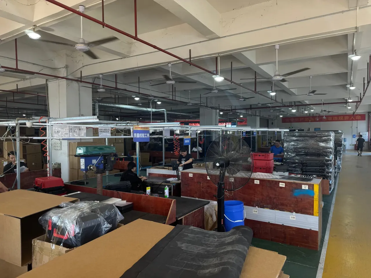
Cavity tolerance on Custom Foam Inserts for Instrument Cases is written +0.5 / 0 mm, meaning oversize only. With a 0.3 mm die allowance the cut pocket lands about 0.15 mm beyond the outline, so the two figures stay inside that 0.5 mm ceiling. Too little allowance and the pocket grips the housing; too much and the wall goes slack.
Dies are bent from 3 mm steel rule, and after several regrinds the allowance drifts by about 0.2 mm, at which point pockets come out undersize. The bench measures pocket length, width and depth on a dial caliper to 0.1 mm, and any one out of tolerance sends the die back for re-nesting.
Cutting pressure tracks density: 70 kg/m³ EVA needs a deeper bite than 30 kg/m³ EPE, so Custom Foam Inserts for Instrument Cases in a new density need the die re-set. A dull edge tears rather than cuts and leaves fuzz that works down to the pocket floor.
5. Keeping a batch consistent by retention samples
Three batches from one drawing differ in the foam rather than in the die. A new foaming lot can shift density by ±5%, the compression curve moves with it, and the same instrument no longer seats the same way. Custom Foam Inserts for Instrument Cases are therefore kept honest by retention blocks, not by complaints.
Each batch keeps 3 bonded blocks labelled with lot, density and lay-up date, and three readings follow: density deviation, colour difference and pocket dimensions. A batch beyond ±5% density does not ship, because compression set drifts with it.
| Retention item | Sampling | Limit |
|---|---|---|
| Bonded block thickness | 3 per batch | 55–58 mm |
| Pocket length and width | 3 per batch | +0.5 / 0 mm |
| Density deviation | Once per batch | Within ±5% |
| Colour difference | Once per batch | ΔE ≤1.5 |
Colour is judged at ΔE ≤1.5, since a lighter insert inside a run of cases stands out at a glance. Blocks are stored 12 months, and a repeat order is checked against the old block before anything is scanned again.
Conclusion
Custom Foam Inserts for Instrument Cases are judged on three measurable positions: a ±0.05 mm scan, 0.25 mm and 0.3 mm added at modelling and die edge, and pockets held to +0.5 / 0 mm; a 20 + 15 + 20 mm lay-up settling at 55–58 mm; and 3 retention blocks per batch watching ±5% density and ΔE ≤1.5. Run the six steps in order and the foam follows the instrument.
Related Reading
- Usable cavity ratio: how much the four corners actually give
- EVA, EPE and XPE inserts compared
- What belongs on a foam insert specification sheet
- Protective plastic case or wooden crate for export
Related Products
- 8 Series — Gun Cases; Military Equipment Cases; Camera Equipment Cases; Drone Cases; Watch Cases; Knife Cases; First Aid Cases; Electronics Equipment Cases
- WL8-2812 PP Gun Case — model WL8-2812
- All protective cases and toolboxes: 7 series, 158 models