

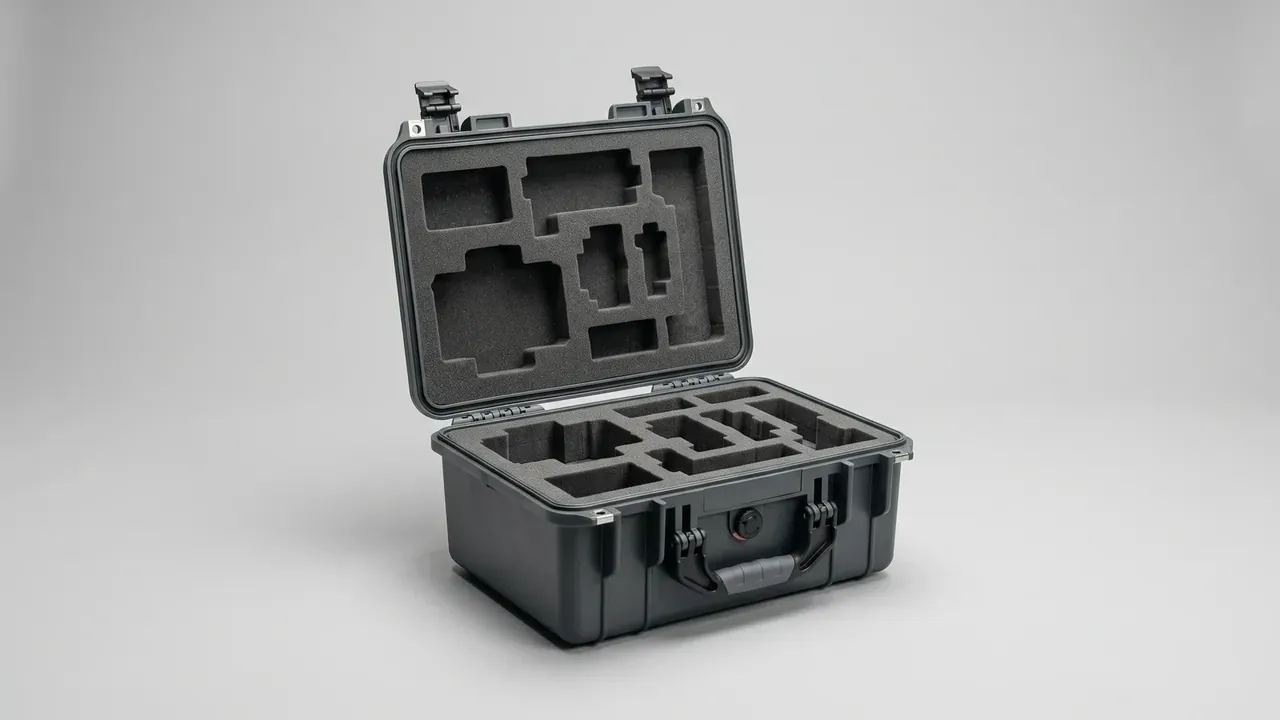
Quick answer: Foam Inventory Management specifications form a five-link chain: load sets density, outline sets the cavity, impact energy sets thickness, load path sets layers, and segment deviation sets clearance.
Table of contents
- Load: Where the Chain Starts
- Cavity: Working Back from the Part Outline
- Wall Thickness: Energy Over Allowable Stress
- Structure: Three Layers and the Bond Line
- Tolerance: How Five Segments Stack Up
- FAQ
1. Load: Where the Chain Starts
The costliest mistake in Foam Inventory Management is treating cavity size as the start. The cavity is an output; the input is load: unit weight, drop height, stack tiers.
Three numbers get measured on site: an 18 kg instrument, a 0.9 m drop, and a 5-high stack putting 90 kg on the bottom case. Double any one of them and the density grade steps up.
| Load source | How to measure | Value here | Parameter it sets |
|---|---|---|---|
| Unit weight | bench scale | 18 kg | density, 45 kg/m³ |
| Drop height | tape to floor | 0.9 m | absorbing thickness |
| Stack load | count tiers | 5 tiers, 90 kg | base pad |
| Vibration | log truck and road | 5–200 Hz, 3 hours | bonding method |
With those numbers, density has a basis: 18 kg sits at 45 kg/m³, units under 10 kg drop to 30 kg/m³, and past 40 kg needs 60 kg/m³.
2. Cavity: Working Back from the Part Outline
The cavity grows out of the part outline. A 380×260×150 mm part with 8 mm per side gives a 396×276×166 mm cavity, and the allowance pays for finger room, wrap cloth and rebound.
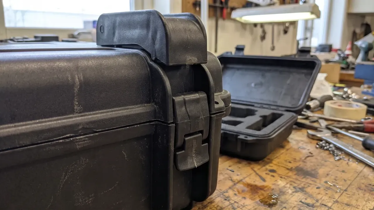
Depth follows orientation: a flat part gets two thirds of its height, a standing part gets full depth with 2 mm of draft per side.
Finger slots are dropped most often. A 35 mm slot at the long-edge midpoint, 25 mm deep, takes a gloved hand; on the short edge the wrist twists.
Two parts sharing a pocket need a 12 mm rib, and no wall between pockets goes under 15 mm, or impact crosses it.
3. Wall Thickness: Energy Over Allowable Stress
Thickness is impact energy divided by allowable stress, rounded up. An 18 kg unit at 0.9 m lands at roughly 160 J; EVA at 60% compression allows 0.35 MPa, which divides to 42 mm and rounds to 45 mm.
| Impact energy | Allowable stress | Calculated | Used | Density |
|---|---|---|---|---|
| 90 J | 0.35 MPa | 24 mm | 25 mm | 30 kg/m³ |
| 160 J | 0.35 MPa | 42 mm | 45 mm | 45 kg/m³ |
| 260 J | 0.40 MPa | 58 mm | 60 mm | 60 kg/m³ |
The 45 mm then splits into 5 mm facing, 30 mm core and 10 mm base.
Stack load runs the other way: 90 kg over a year takes 15% compression and leaves 85% recovery, so the base runs 5 mm thicker than the sides.
At -30 °C, modulus rises about 40%, so cold projects add 10% thickness and drop a sample for 4 hours in a chamber first.
4. Structure: Three Layers and the Bond Line
Structure decides whether the foam stays put; foam that walks out wastes the best thickness calculation.
Layers are bonded, not pinned, with a 0.15 mm glue line: thinner starves the joint, thicker creeps. Acceptance is 0.12 MPa, so a 100×100 mm face carries 120 kg without peeling.
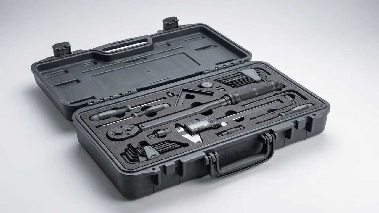
Facing and core are offset 20 mm so no seam lines up, which roughly halves the tear risk. Above 20 removals a year, use six glue dots; below that a full sheet is simpler.
Leave 3 mm at the rim. The lid closes with 2 to 3 mm of preload, and foam that reaches the rim holds the latches open.
5. Tolerance: How Five Segments Stack Up
Tolerance accumulates rather than being granted per segment: cutting ±0.5 mm, material ±1%, assembly ±1.5 mm, cavity ±1 mm, worst case ±3 mm.
| Stage | Segment deviation | Running total | Control |
|---|---|---|---|
| Cutting | ±0.5 mm | ±0.5 mm | first-off check |
| Material | ±1% | ±1.0 mm | three-point gauge |
| Assembly | ±1.5 mm | ±2.5 mm | locating fixture |
| Case cavity | ±1 mm | ±3.0 mm | diagonal check |
So the cavity gets 4 mm of total clearance, not 4 mm per segment. Four per segment reaches 8 mm, the foam shifts in the pocket, and impact hits the case wall first.
Clearance follows direction: the long edge gets 1 mm more because it shrinks more, while thickness gets none, because preload makes the cushion work.
Load, cavity, thickness, structure and tolerance each carry one number, and changing one sends the other four back through. Those five numbers are Foam Inventory Management on a drawing.
Conclusion
Foam Inventory Management specifications behave as a chain, not a table. Write the five numbers in one block on the drawing, and quoting, sampling and inspection finally share one ruler. That is what makes Foam Inventory Management repeatable.
This article discusses only the container (case body) side of specifications and design intent, and does not cover any handling, loading or use of the contents.
Related Reading
- How a custom case insert spec is derived
- Density and thickness values for EVA inserts
- Matching pocket shape to the part outline
- Inspection dimensions for protective case inserts
- Setting cutting tolerances on foam
Related Products
- 8 Series — Gun Cases; Military Equipment Cases; Camera Equipment Cases; Drone Cases; Watch Cases; Knife Cases; First Aid Cases; Electronics Equipment Cases
- WL8-2812 PP Gun Case — model WL8-2812
- All protective cases and toolboxes: 7 series, 158 models