

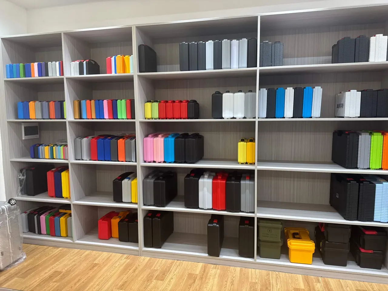
Quick answer: A hard plastic equipment case with pick and pluck foam is decided where shell and liner meet. The body gives a 3.5 mm wall and a 12 mm sealing land; the liner closes six faces with 30 kg/m³ grid foam. A 15 mm grid cut to 70% of board thickness tears flat, and the air test passes at 3 kPa with a drop under 0.3 kPa in 60 seconds.
Table of contents
- Shell Structure and the 3.5 mm Wall
- Grid Pitch and Pre-Cut Depth
- Three Foam Layers
- Gasket Compression and the Pressure Valve
- Pass Lines for Air, Drop and Stack Tests
- FAQ
1. Shell Structure and the 3.5 mm Wall
The shell sets the floor: put 30 kg/m³ foam behind a 2.5 mm wall and a 1.2 m drop bulges the side before the foam travels 20% of its stroke.
Wall thickness comes from outside length. Under 400 mm, mould 2.8 to 3.2 mm. From 400 to 600 mm, use 3.5 mm. Above 600 mm, use 4 mm plus an 8 mm rib along the long side, spaced no wider than 80 mm. Empty weights land near 1.2, 2.0 and 3.4 kg.
Ribs fail at the root: twice the wall thickness, slow to cool, and a sink mark lands on the sealing land where the gasket cannot seat. Hold rib thickness at 0.6 of the wall and the mark stays under 0.05 mm.
The sealing land is the flat ring where lid and body meet: 10 to 14 mm wide, flat within 0.2 mm. Narrower and the gasket rides onto the corner radius; wider and closing force spreads thin. Two latches carry a 400 mm case, four carry 600 mm, each on 3 mm of solid plastic.
| Outside length | Wall | Rib height | Empty weight | Inner depth |
|---|---|---|---|---|
| Under 400 mm | 2.8–3.2 mm | 6 mm | 1.2 kg | 60–90 mm |
| 400–600 mm | 3.5 mm | 8 mm | 2.0 kg | 90–140 mm |
| Over 600 mm | 4.0 mm | 8 mm | 3.4 kg | 140–200 mm |
2. Grid Pitch and Pre-Cut Depth
Pick and pluck foam is properly pre-cut grid foam: a die cuts a square array and leaves the bottom 20% to 30% intact. Bend along a seam and the bridge tears away flat.
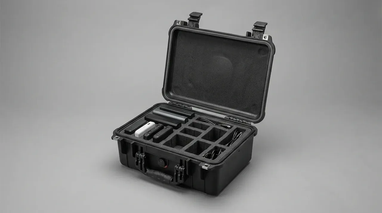
Pre-cut depth has no room to negotiate. At 60% the blocks skew instead of separating; at 90% the remaining skin splits under road vibration and cavities collapse before shipping. Thick boards take the low end: 38 mm on a 50 mm board, 23 mm on a 30 mm board.
Pitch follows the outline: a 10 mm pitch suits parts under 50 mm but leaves a wall one cell wide that frays at the corners. A 15 mm pitch covers instruments from 50 to 120 mm; above 150 mm, step to 20 mm and keep two cells unbroken at each end.
Interference sits at 1 to 2 mm: one lets gravity seat the part, two buy zero movement at the cost of hand pressure. Die tolerance is ±0.3 mm, and torn walls stay vertical above 30 kg/m³.
| Pitch | Board | Pre-cut | Part outline | Torn wall |
|---|---|---|---|---|
| 10 mm | 20 mm | 16 mm | Under 50 mm | One cell, frayed |
| 15 mm | 30 mm | 23 mm | 50–120 mm | Two cells left |
| 20 mm | 40 mm | 30 mm | 120–200 mm | Two cells required |
| 25 mm | 50 mm | 38 mm | Over 200 mm | Pair with 2 mm base |
3. Three Foam Layers
Liner thickness is subtraction: at a 120 mm inner depth with 15 mm lid foam, 10 mm base foam and a 2 mm allowance, the pluck layer is 93 mm, rounded to 90 mm so the lid preloads by 3 mm.
- Lid foam: 10 to 15 mm, flat for machined faces, convoluted for curved loads, compressed 15% to 25%.
- Pluck layer: 30 to 90 mm for lateral location; unbroken end cells act as the shear zone.
- Base foam: 8 to 10 mm for the landing, 5 kg/m³ lighter than the pluck layer.
The lid compresses 3 to 5 mm, the pluck walls cut movement to 0.5 mm, and the base foam drops peak acceleration from 40 g to below 25 g.
4. Gasket Compression and the Pressure Valve
Sealing comes from compression, not latch force. An O-ring forms a continuous band only when flattened 20% to 30%; under 20% the band breaks and 3 kPa escapes, over 35% the rubber takes a permanent set.
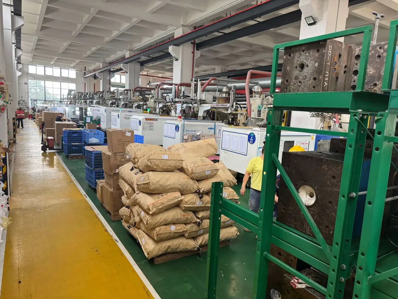
Size the groove from the cord: width 1.3 times, depth 0.75 times, fill 75% to 85%. A 4 mm cord needs a 5.2 mm wide, 3.0 mm deep groove for 25% compression. Past 90% fill, closing force climbs from 60 N to 110 N.
Compound follows temperature: EPDM covers -40 to 120 °C and resists UV, so it suits outdoor storage; silicone covers -60 to 200 °C with better rebound for cold stores and air freight.
A pressure valve solves differential pressure, not water: it opens at 3 to 5 kPa with about 0.5 L/min of flow for aircraft holds and high-altitude trucking. A diaphragm inside stays closed to water; replace the valve when it ages.
5. Pass Lines for Air, Drop and Stack Tests
Run the air test before the drop test, or micro-cracks in the wall will fail it and hide whether the fault came from design or the fall.
| Test | Condition | Pass line |
|---|---|---|
| Air | 3 kPa for 60 s | Drop under 0.3 kPa |
| Immersion | 1 m for 30 min | No visible water inside |
| Drop | 1.2 m, six faces, -20 °C for 4 h | No cracks, latches closed |
| Stack | 500 kg for 24 h at 40 °C | Under 3 mm, 80% recovery |
| Salt spray | 48 h neutral | No red rust |
Test the first article on every item, then sample air at AQL 2.5, pulling three units per batch for drop. Tested units never return to the packing line; a drop leaves invisible craze that understates the next result.
Conclusion
Choose in four steps: fix pitch and interference from outline and weight, subtract layers from inner depth, match the gasket to service temperature, then write air, drop and stack lines into the drawing. Skip a step and the cost returns as rework.
This article covers container-side specifications and design implications only.
Related Reading
- How density and hardness change a custom foam insert
- Choosing 5, 10 or 15 mm foam thickness
- Die cutting, CNC routing and laminated foam compared
- Reading a 3 kPa, 60-second air test
Related Products
- 8 Series — Gun Cases; Military Equipment Cases; Camera Equipment Cases; Drone Cases; Watch Cases; Knife Cases; First Aid Cases; Electronics Equipment Cases
- WL8-2812 PP Gun Case — model WL8-2812
- All protective cases and toolboxes: 7 series, 158 models