

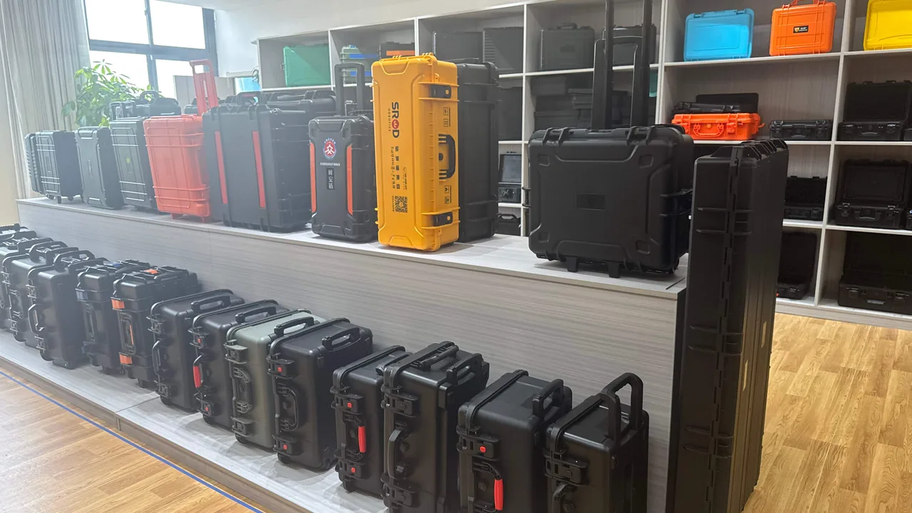
Hydroelectric maintenance windows are squeezed into the few short weeks of the dry season, and oversized parts such as guide vanes, runners, servomotors, and guide bearings must be removed, shipped to a workshop, repaired, and reinstalled inside that narrow slot. Most of these components are stainless steel castings or finish-machined parts. A single vane can weigh tens of kilograms while a runner can reach tens of tonnes, and contact faces on sealing surfaces and spigots are frequently machined to Ra1.6 or even Ra0.8. One impact, one deep scratch, or one night of condensation-induced rust during transit can force on-site grinding and re-scraping with a floor-type boring mill or a large vertical lathe, destroying both schedule and budget.
JUNZHIJIA designs hydro turbine protection at the component level rather than the box level: the sensitive features of every part — fitted faces, coatings, bearing pads, seal grooves, and overhanging length — are quantified first, and the shell stiffness, liner stiffness, and restraint method are then derived from those numbers. High-impact engineering-plastic shells, compartmented locating liners, desiccant management, and pressure equalization valves, validated against the GB/T 4857 and ISTA test families, are what allow precision hydro turbine components to arrive at the powerhouse in the same condition they left the workshop, even after multimodal road, rail, and sea transport.
Table of Contents
- Transport Risk Profile of Hydro Turbine Components
- Guide Vanes: Protecting Precision Fits and Sealing Faces
- Runners and Runner Chambers: Supporting Heavy Mass Without Distortion
- Servomotors and Actuating Mechanisms: Cleanliness and Sealing
- Guide Bearings and Bearing Pads: Deformation- and Moisture-Sensitive Parts
- Cavitation and Sand-Erosion Zones: Protecting Coatings and Weld Overlays
- Case Shell Structure: Reinforcement Ribs and Stacking Load
- Liner Design: Foam Selection and Compartmentalization
- Sealing and Environmental Protection: IP Ratings, Pressure Equalization, and Rust Prevention
- Transport Testing and Acceptance Criteria: ISTA, GB/T 4857, and ASTM D4169
- Failure Mode and Countermeasure Reference Table
- Customization, OEM/ODM, and Documentation
- Frequently Asked Questions FAQ
- Conclusion and Related Reading
Transport Risk Profile of Hydro Turbine Components
The risk profile of a hydro turbine shipment is not one-dimensional. It is a stack of mechanical shock, sustained vibration, temperature and humidity cycling, salt-laden air, and manual handling. Mechanical shock peaks during crane landing and hard braking, where recorded accelerations of 10 g and above are common. Sustained vibration comes from rough road surfaces, rail coupling impacts, and ship main-engine excitation; a long narrowband input can drive a structural resonance, loosening fasteners and fatiguing overhung parts. On the humidity side, repair routes in mountainous and coastal regions often cross both wet and dry seasons, and the day-night temperature swing creates a breathing effect that repeatedly condenses moisture onto colder steel surfaces.
Salt spray and chemical contamination deserve equal attention. Coastal storage yards, humid workshop floors, and salt-bearing air inside a sea container all leave pitting initiation sites on stainless steel vanes. If a component was just pulled from silt-laden water, the residual mud and moisture form local galvanic and concentration cells that accelerate attack. Manual handling is where human factors concentrate: forklift impacts, sling bruises, and a single uncontrolled roll during a flip can destroy a month of finish machining in seconds.
A sound approach starts with risk classification. Parts are grouped into A, B, and C tiers according to sensitive features, mass, overhang, and surface condition. Tier A covers exposed precision fits, high unit value, and long repair lead times — guide vanes, runner spigots, servomotor piston rods. Tier B covers coated or weld-overlaid surfaces that can be repaired in the field, such as runner blades and wear plates. Tier C covers structural and general parts such as flanges, covers, and support frames. Each tier maps to a different shell strength, liner hardness, and restraint method instead of one generic box being applied to everything.
Guide Vanes: Protecting Precision Fits and Sealing Faces
The guide vane, including both the movable and stay-ring types, is the core element of the distributor. A movable vane rotates about its trunnion to regulate flow, and its upper and lower journals and the link holes of the vane arm and regulating ring are precision fits. Journal diameters are typically held to IT7, and the contact faces against the head cover and bottom ring require Ra0.8 to Ra1.6. The material is usually a low-carbon martensitic stainless steel such as ZG06Cr13Ni4Mo or ZG06Cr13Ni5Mo, or an ASTM A743 CA6NM grade. These alloys are tough but not hard, which means a hard object can carve a groove into them.
Three protection priorities follow. First, no contact on fitted faces: journals and sealing faces must be suspended or carried on soft foam, never laid against a shell wall or a metal divider, because micro-motion during transport produces fretting wear. Second, distortion control: a long vane, especially a slender high-head design, sags under its own weight, so multiple supports must be distributed along its length, with spacing calculated from the slenderness ratio to avoid residual deflection after storage. Third, rust prevention: stainless steel is not immune to corrosion, and chloride exposure or trapped silt can initiate pitting, so journals and sealing faces should be cleaned, dried, coated with a thin film of rust-preventive grease or wrapped in vapor-phase corrosion inhibitor film, and then loaded.
For fixturing, guide vanes are usually carried either in a vertical slot arrangement or on a horizontal toothed cradle. The vertical slot suits batch shipments, using EVA tooth blocks that grip the journal while leaving 15 to 25 mm between adjacent parts. The horizontal cradle suits very long vanes, using two or more curved blocks that support non-working surfaces so the fitted faces hang free. In either case the vane must not shift under a 60 cm drop or under sustained 3 g vibration.
Runners and Runner Chambers: Supporting Heavy Mass Without Distortion
The runner is the component that converts hydraulic energy into rotation, and it is also one of the hardest parts to ship. A Francis runner is fabricated or cast-welded from a crown, a band, and a set of blades, and can range from 1 m to more than 8 m in diameter and reach tens of tonnes. A Kaplan runner adds a hub, adjustable blades, and a blade-operating mechanism. A Pelton runner carries buckets on a disc, and the bucket roots are stress concentrators that tolerate almost no impact.
The central conflict for heavy parts is that too few support points crush the contact zone while too many introduce assembly stress. The engineering answer is to place three or four statically determinate supports beneath the crown or hub, using steel or high-polymer pads of adequate stiffness, with a 10 to 20 mm layer of IXPE or EVA between the pad and the workpiece so contact stress stays within the elastic range of the material. For a runner shipped horizontally, curved cradles and thrust blocks must prevent rolling, and radial stops must prevent lateral creep during cornering.
Blade leading and trailing edges are thin-walled and weak in bending, so straps must never be cinched directly around them. Soft slings of adequate width should be combined with custom cradles, or support wedges placed between blades so that transport loads transfer into the crown and band. For a runner that has already been statically balanced, whether to re-verify balance after delivery is the user's decision; with sound shell stiffness and liner design, and no abnormal impact recorded, re-balancing is usually unnecessary.
Runner chambers, bottom rings, and head covers are annular heavy parts whose critical features are the spigot faces and the bolt-hole pattern. They are usually laid flat on a ring of evenly spaced support blocks placed inside the spigot circle, leaving the spigot face clear, with a central locating core to stop radial movement and limit blocks above and below to make the stack load path unambiguous. When specifying these ring-shaped items, compare the approach used in Dam Gate and Hoist Component Cases.
Servomotors and Actuating Mechanisms: Cleanliness and Sealing
The servomotor, whether an electro-mechanical actuator or a pure hydraulic cylinder, drives the guide vanes or the runner blades. Its piston rod is normally hard-chrome plated or laser-clad, with a surface roughness of Ra0.2 to Ra0.4, making it one of the finest surfaces on the entire unit. A scratch on the rod damages the seals directly and causes internal leakage, which in turn allows the vane opening to drift out of control. The protection priorities are therefore zero contact on the rod surface and a clean internal cavity.
During transport, a servomotor is normally retracted and mechanically locked, or its two chambers are filled with clean hydraulic oil and the ports are plugged. Ports must be closed with dedicated plugs or dust caps; ordinary tape is unacceptable because adhesive residue migrates into the hydraulic system. The exposed rod should be wrapped in lint-free cloth or a dedicated sleeve and then covered by a rigid guard so the rod is fully isolated from other cargo. The complete actuator should rest horizontally in V-shaped or curved saddles, with saddle spacing calculated from barrel stiffness to prevent sagging.
Position feedback sensors, proportional valves, and displacement transducers inside the actuating mechanism should be treated according to the resonance avoidance principles described in Vibration Mechanisms and Resonance Avoidance: stay clear of the resonance band shared by the case and the vehicle chassis, and wrap each sensor in an independent soft cushion so that high-frequency vibration cannot loosen terminals or wear slip rings. All electrical items belong in anti-static bags, in a compartment separate from hydraulic parts, to keep oil mist and metal chips away.
Guide Bearings and Bearing Pads: Deformation- and Moisture-Sensitive Parts
Hydro turbine guide bearings fall into water-lubricated and oil-lubricated families. Water-lubricated bearings commonly use rubber, composite, or ceramic faces and are sensitive to oil contamination, while oil-lubricated bearings use babbitt, or white metal, pads. Babbitt is soft and has a low melting range of roughly 180 to 240 degrees Celsius, so improper support can cause creep or even detachment. The clearance between the pad face and the shaft is only a fraction of a millimeter, so any distortion immediately changes the operating condition of the unit.
The first rule for shipping bearing pads is preserve the original shape. Babbitt pads must rest on dedicated curved saddles whose curvature matches the pad back, so contact pressure is even. Laying a pad flat on a plate, or cinching a strap across the pad opening, is not acceptable. The second rule is moisture and contamination control: white metal is sensitive to water and acidic environments, so it should be coated with rust-preventive oil and wrapped in vapor-phase inhibitor film, while rubber faces must be shielded from oil, ultraviolet light, and heat. The third rule is temperature control: some composite pads soften at elevated temperatures, and a container or truck body in summer can exceed 60 degrees Celsius, so prolonged direct sun exposure should be avoided and a light-colored shell chosen to reduce heat absorption.
Support rings and oil-bath housings for guide bearings are handled as ordinary precision machined parts, with attention to fitted faces and oil passage ports. Oil ports must be plugged to keep debris out, and fitted faces coated with rust-preventive grease and covered with neutral paper. A complete bearing set is best shipped in its own case or its own compartment, never mixed with heavy parts, so that it can never be crushed under any circumstance.
Cavitation and Sand-Erosion Zones: Protecting Coatings and Weld Overlays
Flow-passage components of a hydro turbine endure cavitation and sand erosion for years. Cavitation produces honeycomb pitting on the suction side of blades, while sand erosion concentrates on blade leading edges, the band, and the runner chamber wall. Repairs are normally made by grinding and then weld-overlaying stainless filler, or by thermal spraying tungsten carbide or nickel-based alloys. These repaired layers are much harder than the parent metal but have limited ductility, so an impact chips the coating edge, and the chipped edge becomes a new cavitation initiation site in a self-reinforcing cycle.
Protection for a repaired or sprayed flow surface is therefore one tier higher. First, the repaired zone must never touch a hard material directly; the liner should be low-hardness and high-rebound EVA or PE foam, and contact pressure must stay within the allowable range of the coating. Second, the coating edge, the step where parent metal meets overlay, should be wrapped in a soft corner protector so edges cannot shear against each other. Third, an impact recorder should travel with the shipment so that, if any acceleration peak exceeds the threshold, the repaired layer can be visually inspected and dye-penetrant tested before installation.
In-service blades that have not been repaired must also be protected from new damage. A blade leading edge is often thin and sharp, and during transport it can cut into adjacent parts. The accepted practice is to fit a split soft edge strip over the leading edge, install removable support blocks between blades, and mark the case with a no-hook warning. These edge strips are consumable or reusable accessories and should be counted in and out with the workpiece so the set reassembles correctly.
Case Shell Structure: Reinforcement Ribs and Stacking Load
A hydro turbine protective case must balance lightness and rigidity. Too heavy and freight cost and lifting risk rise; too soft and the heavy internal mass is not restrained. Common shell materials include PP, ABS, PC, PC/ABS alloy, and rotationally molded PE. Selection should weigh impact strength, low-temperature brittleness, UV resistance, chemical resistance, and recyclability rather than price alone.
| Shell material | Impact strength | Low-temperature behavior | Chemical resistance | Typical use | Cost |
|---|---|---|---|---|---|
| --- | --- | --- | --- | --- | --- |
| PP homopolymer/copolymer | Medium-high | Good above -20 C | Excellent | General medium and large parts, chemical environments | Low |
| ABS | High | Fair, brittle near -20 C | Good | Precision medium parts, high cosmetic requirements | Medium |
| PC | Very high | Excellent, usable to -40 C | Fair, weak against alkalis and solvents | High-value precision parts, cold-chain transport | High |
| PC/ABS alloy | High | Good | Good | Large heavy parts, balanced performance | Medium-high |
| Rotomolded PE | Very high, monolithic | Excellent | Excellent | Oversized, irregular, and very heavy parts | High, including tooling |
Several structural points matter. Reinforcement ribs should run along the primary load path in a cross-hatched grid, with a rib height to wall thickness ratio generally kept under 5:1 to avoid sink marks and stress concentration. Stacking load is checked against the worst case, in which the bottom case carries the full weight above it; a static load of 1.5 to 2 times the stacked weight held for 24 hours with no visible deformation is a common requirement. Lifting points should sit near the vertical projection of the loaded center of gravity, using embedded metal lifting pads or thickened lugs, and slings must never be passed around shell corners. Base geometry must provide clearance for forklift tines and anti-slip feet to stop stacked cases from creeping.
Liner Design: Foam Selection and Compartmentalization
The liner decides whether an impact load is cushioned or transmitted. Liner design for hydro turbine parts begins with two parameters: the allowable peak acceleration, set by component sensitivity, and the available cushioning stroke, set by the space left inside the case. The two are related in an intuitive way: a longer stroke allows softer foam, while a shorter stroke demands denser foam. One foam type therefore cannot serve every part.
| Foam | Density range | Rebound | Compression set | Typical use |
|---|---|---|---|---|
| --- | --- | --- | --- | --- |
| EPE | 20-35 kg/m3 | Good | Medium | Large-area padding, void filling |
| EVA | 40-90 kg/m3 | Excellent | Low | Precision cradles, toothed locating blocks |
| High-density PE | 30-60 kg/m3 | Medium | Medium | Heavy-part support, puncture resistance |
| IXPE | 30-50 kg/m3 | Good | Low | Thin cushioning, curved surface bonding |
| PU sponge | 20-40 kg/m3 | Medium | High | Low-demand filling, not recommended for heavy parts |
| Flame-retardant EVA | 40-80 kg/m3 | Excellent | Low | Electrical items, enclosed compartments |
Compartmentalization assigns one location to each item. Heavy parts sit near the geometric center and the base of the case, while light parts and accessories occupy the perimeter. Neighboring parts keep adequate separation and are isolated by individual cradles, and every cradle is fixed to the shell by adhesive or a mechanical latch so it cannot fall out when the case is empty. EVA cradles are usually CNC-carved or thermoformed to plus or minus 0.5 mm, which lets them follow the curved surfaces of a vane journal, a runner spigot, or a piston rod. Liner faces can be flocked or covered with fabric to reduce abrasion against the workpiece. For a deeper comparison of foam behavior, see Case Foam Material Comparison.
Sealing and Environmental Protection: IP Ratings, Pressure Equalization, and Rust Prevention
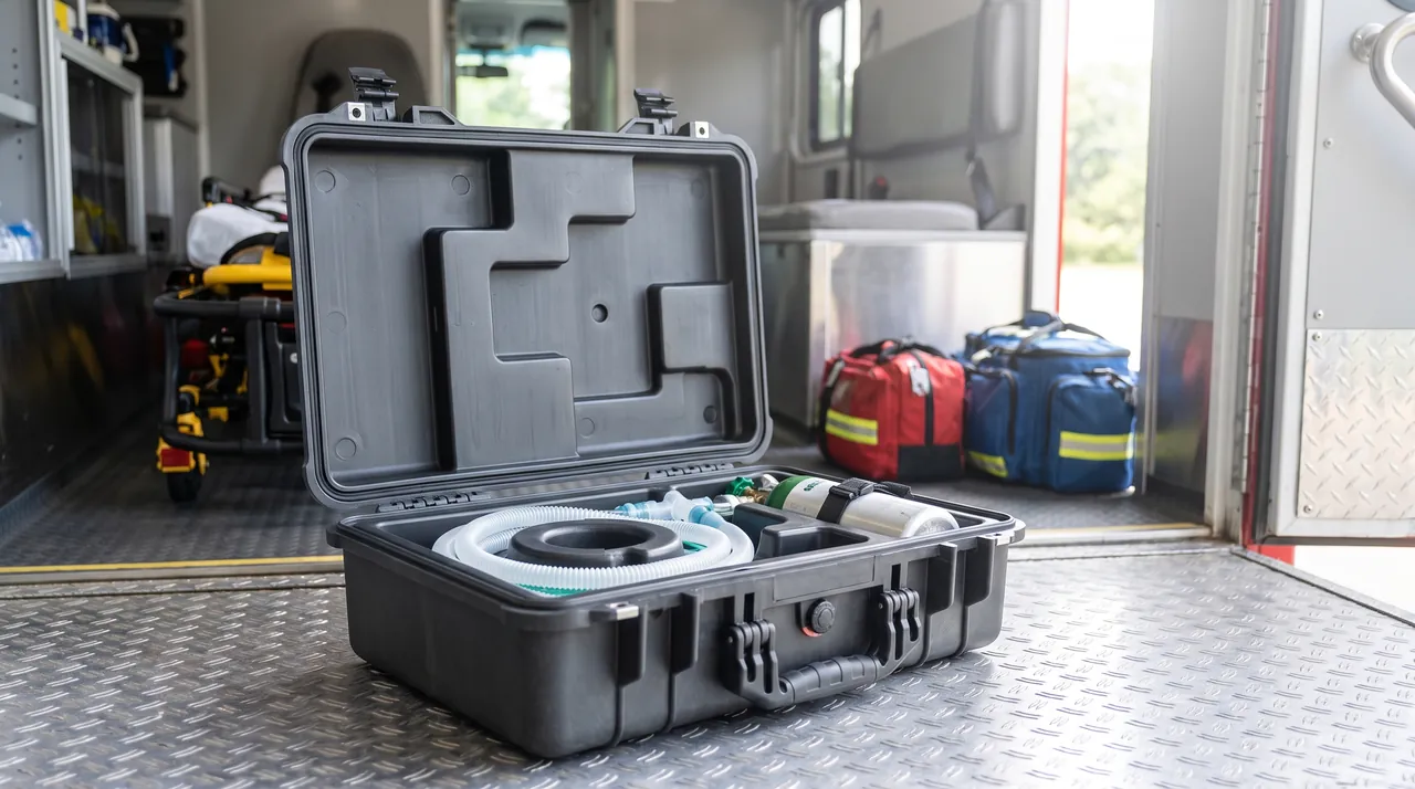
The goal of case sealing is not absolute watertightness but a stable internal microclimate under defined conditions. Ingress protection is defined by GB/T 4208 and IEC 60529, and hydro turbine cases commonly use IP65 for water jets and IP67 for short-term immersion. Sealing depends on a continuous elastomer gasket around the case opening, usually silicone, EPDM, or foamed PU, compressed by 25 to 40 percent; excessive compression accelerates aging rather than improving the seal.
The pressure equalization valve is a small but critical component that is often overlooked. Temperature changes or altitude changes create a pressure differential across the shell, and a fully sealed case under a large differential becomes hard to open, sucks the gasket inward into a permanent set, and can even bulge the shell. The valve equalizes pressure within a permissible range while an ePTFE waterproof breathable membrane blocks liquid water and dust. For sea freight, the container's day-night temperature swing and dew point should be calculated, and desiccant plus a humidity indicator card placed inside as needed.
Rust prevention is the other main line of defense. Stainless steel still suffers pitting and crevice corrosion, especially in chloride environments. Accepted practice includes cleaning and drying the part before applying a thin rust-preventive grease or oil; covering fitted faces with vapor-phase corrosion inhibitor film; placing desiccant inside without direct contact with the workpiece; and inspecting periodically during long-term storage, re-coating when necessary. Material and test requirements are covered in Salt Spray Corrosion Testing. For ground sealing faces on guide vanes and for servomotor piston rods, silicone- or wax-based cheap protective agents must not be used, because they contaminate hydraulic systems and seals.
Transport Testing and Acceptance Criteria: ISTA, GB/T 4857, and ASTM D4169
A protective case is not proven until it has been tested. The test systems commonly applied to hydro turbine cases are the ISTA series, where test 1A, 2A, or 3E is selected by package weight and transport mode; the GB/T 4857 series covering drop, stacking, vibration, and shock; and ASTM D4169, which sets test intensity according to a defined distribution cycle. The objective is not to pass once, but to close the loop of design, test, failure, and improvement.
Acceptance criteria must be tied to component sensitivity. For Tier A parts, acceptance usually requires no cracks or permanent deformation in the shell; no liner collapse and no cradle displacement; relative movement between part and case within a set limit; critical dimensions re-measured within tolerance; and no new scratches or rust spots. Tier B parts may skip some dimensional checks but still require visual and coating-integrity inspection, while Tier C parts are accepted on structural integrity and functional availability.
| Test | Reference standard | Typical parameters | Acceptance focus |
|---|---|---|---|
| --- | --- | --- | --- |
| Drop | ISTA 1A/2A, GB/T 4857.5 | Weight-graded, 60-120 cm | No shell cracks, no liner penetration |
| Stacking | GB/T 4857.3, ASTM D4169 | 1.5-2x stacked weight, 24 h | No permanent set, dimensional recovery |
| Vibration | GB/T 4857.7, ISTA 3E | Random or sinusoidal, 1-3 h | No displacement, no fastener loosening |
| Shock | ASTM D4169, GB/T 4857.11 | Half-sine, peak by level | Recorder stays below threshold |
| Spray/immersion | IEC 60529, GB/T 4208 | IP65/IP67 | No ingress, no condensation |
| Salt spray | GB/T 10125 | 96-480 h | No spreading white or red rust |
Note that every test is only a simulation of a specific load spectrum and cannot cover all real conditions. Users should define the test plan from their own route, handling conditions, and storage period, and write the acceptance criteria and responsibility split into the contract. Test reports and impact recorder data should travel with the shipment as the basis for later claims and improvements.
Failure Mode and Countermeasure Reference Table
The most common transit failure modes are collected in the following table so they can be checked one by one during a design review. The table is used in a locate-then-counter approach: identify which row the failure belongs to, then verify that the corresponding design, process, and handling measures are actually in place.
| Failure mode | Primary cause | Countermeasure | Verification |
|---|---|---|---|
| --- | --- | --- | --- |
| Scratched fitted face | Direct hard contact, micro-motion | Suspended support, soft cradles, separate compartments | Visual plus roughness re-check |
| Out-of-tolerance distortion | Too few supports, long storage | Multiple statically determinate supports, limit blocks | CMM or laser measurement |
| Pitting corrosion | High humidity, chloride, trapped silt | Clean and dry, rust grease, VCI film, desiccant | Visual plus salt spray re-test |
| Chipped coating | Impact with hard objects, edge shear | Corner protectors, soft liner, inter-blade supports | Visual plus dye penetrant |
| Bearing pad creep | Mismatched support surface, heat | Curved saddles, shading and insulation | Dimensional re-check |
| Piston rod damage | Exposed rod, abrasive accessories | Sleeve plus rigid guard, separate compartment | Surface roughness check |
| Loosened fasteners | Sustained vibration, resonance | Locking features, avoid resonance band | Torque re-check |
| Difficult opening | Excessive pressure differential, no valve | Equalization valve with ePTFE membrane | Opening force test |
| Internal condensation | Breathing effect, temperature cycling | Desiccant, humidity indicator card | Humidity log |
| Stack collapse | Insufficient shell stiffness, off-center load | Ribs, load check, aligned center of gravity | Static load test |
| Displaced cradle | Empty-case transit, adhesive failure | Mechanical latches, individual packing | Opening inspection |
| Missing identification | Incomplete documentation | Checklist delivery, QR tracking | Receipt verification |
Customization, OEM/ODM, and Documentation
The dimensional spread of hydro turbine components is enormous, from a vane journal only tens of centimeters long to a runner several meters across, so a truly universal standard case barely exists. Protection therefore follows a custom route: the user supplies a 3D model or critical dimensions, weight, center of gravity, a list of sensitive faces, and the transport route, and the case builder then models the liner, selects the shell, and validates the design by testing. JUNZHIJIA provides one-stop customization from 3D liner modeling, CNC foam carving, and shell tooling to volume production, and can co-develop OEM and ODM programs against customer drawings.
Documentation is easily overlooked yet it determines reinstallation efficiency on site. A recommended document pack includes the packing list and case layout drawing, a part-to-case numbering cross-reference, the liner layout drawing, lifting point and center-of-gravity notes, the rust-preventive and desiccant replacement schedule, impact recorder readings, test report numbers, and opening and reinstallation precautions. For a large unit shipped in many cases, a QR code on each case can display part numbers, quantities, and photos of the contents for fast on-site verification.
Before signing, the acceptance criteria, test plan, spare parts supply, and warranty period should be written clearly. Manufacturing is credited to Kexin New Materials (Guangdong) Co., Ltd. For volume deliveries, agree on liner reuse and replacement policy as well: the outer shell can serve for years, but foam liners age and lose rebound, so evaluation at three to five years or every ten heavy shipments is a practical guideline.
Frequently Asked Questions FAQ
Q: Why must guide vane fitted faces never touch the case wall or a steel divider during transport?
A: Guide vane journals and sealing faces are often held to IT7 with a roughness of Ra0.8 to Ra1.6, so any direct hard contact produces fretting wear under vibration, carving shallow grooves that are difficult to see with the naked eye. The damage then compounds in a predictable sequence: a groove collects moisture and silt, promoting pitting and crevice corrosion, and after installation the imperfect seal leaks, which can force a second outage. Protection design must therefore keep fitted faces suspended or carried on soft material rather than simply surrounded by packaging. The usual method is an EVA or IXPE toothed block that grips the non-working journal surface, with each block secured to the shell by a mechanical latch or adhesive so it cannot shift, and 15 to 25 mm of clearance kept between adjacent vanes. Where a rigid divider is unavoidable, add at least a 10 mm soft cushion between divider and workpiece and protect every corner. On arrival, inspect each fitted face under good light; if anything looks doubtful, re-check roughness and run a dye penetrant test before installation.
Q: For a runner weighing tens of tonnes, how should case stacking load be verified?
A: For a runner weighing tens of tonnes, stacking load must be checked against the worst case, in which the bottom case carries the full weight of every case and part stacked above it. Accepted practice requires that a single case withstand a static load of 1.5 to 2 times the stacked weight for 24 hours with no visible permanent deformation, while a local stress analysis of the base and side walls confirms that rib roots and weld lines are not overstressed. Three points deserve special attention. First, whether the center-of-gravity projection falls inside the load-bearing area, because eccentric stacking multiplies local pressure and can tip the whole stack. Second, whether the load path is continuous, with cradles, liner, and base forming an unambiguous force chain. Third, whether total stack height still fits the clearance of the transport vehicle and the container door. For very large runners the better strategy is often one part per case, shipped horizontally with no stacking at all, moving the stacking requirement onto pallet and trailer planning instead of simply thickening the shell.
Q: How is zero contact on a servomotor piston rod achieved, and what details matter?
A: A piston rod is normally hard-chrome plated or laser-clad with a roughness of Ra0.2 to Ra0.4, so any scratch damages the seal pair and causes internal leakage, and leakage in turn lets the vane opening drift out of control. The method is to apply a thin film of dedicated rust-preventive grease to a clean, dry rod, wrap it in lint-free cloth or a purpose-made sleeve, and then cover it with a rigid guard so the rod is fully isolated from other cargo. Ports must be closed with dedicated plugs rather than tape, because adhesive residue migrates into the hydraulic circuit. The complete actuator rests horizontally in V-shaped or curved saddles whose spacing is set from barrel stiffness to prevent sag. Electrical items such as displacement transducers and proportional valves go into anti-static bags in a compartment separate from hydraulic parts to keep oil mist and metal chips away. During handling, never use a pry bar or wire rope near the rod, and place lifting points at the end flanges. If a slight mark is found on opening, polish it per the manufacturer's procedure and re-check roughness.
Q: Why does a protective case need a pressure equalization valve, and what happens without one?
A: Temperature and altitude changes during transport create a pressure differential across the shell. By the ideal gas relationship, a 20 degree Celsius swing or a few hundred meters of altitude change produces a meaningful differential, and the same effect appears when a container travels from a cool port into tropical heat. If the case is fully sealed, three consequences follow. It becomes hard to open because of the differential, sometimes requiring a tool that damages the gasket or the opening rim. The gasket is drawn inward under the differential and takes a permanent set, degrading its water resistance afterwards. And the shell undergoes repeated bulge-and-contract cycles, so welds and rib roots can develop fatigue cracks over a long service life. An equalization valve balances pressure within an allowable band while an ePTFE waterproof breathable membrane blocks liquid water and dust. When specifying the valve, check its cracking pressure, airflow, and ingress rating, and confirm stability across the expected temperature range. For long sea voyages, pair the valve with desiccant and a humidity indicator card.
Q: Stainless steel guide vanes and runners still rust, so how should rust prevention be performed?
A: The corrosion resistance of stainless steel comes from a passive film, and that film is destroyed by chloride ions, abrasive silt, and oxygen-starved crevices, which leads to pitting and crevice corrosion. A part just removed from silt-laden water can carry residues that form galvanic and concentration cells and accelerate local attack, so the risk is highest right after dismantling. A crevice also forms wherever foam or a gasket presses against metal for weeks, and that trapped zone deserves dedicated inhibitor paper rather than a bare contact surface. The correct sequence is to remove silt and oil, dry the part thoroughly, and passivate it if necessary; then apply a thin film of rust-preventive grease or oil to fitted and bare metal surfaces, avoiding cheap silicone- or wax-based products that contaminate hydraulic systems; cover fitted faces with vapor-phase corrosion inhibitor film; place desiccant inside the case without direct contact with the workpiece; and inspect and re-coat periodically during long storage. For sea freight, verify performance with a GB/T 10125 salt spray test and adjust protective layer thickness and replacement interval according to the result.
Q: How should liner foam be selected, and where do EPE, EVA, and IXPE each fit?
A: Foam selection matches three quantities: impact energy, allowable stroke, and contact stress. EPE has low density, low cost, and good rebound, making it suitable for large-area padding and void filling, but its puncture resistance and load capacity are limited, so it should not support heavy parts directly. EVA has high density, excellent rebound, and low compression set, which makes it the first choice for precision cradles, toothed locating blocks, and load-bearing pads, including vane journals, runner spigots, and servomotor saddles. IXPE is thin and conformable, well suited to curved surface bonding and thin cushioning, and is often used on blade edge strips and fitted face covers. High-density PE resists puncture and carries load, so it works well under heavy parts and at the base of a case. PU sponge has weaker rebound and aging resistance and is not recommended for heavy or long-cycle shipments. Real designs combine layers: PE for load bearing at the base, EVA for locating in the middle, and IXPE or fabric at the contact surface. Confirm density, hardness, and compression set before use, and always run a part-to-liner fit test.
Q: When qualifying a protective case, how should ISTA, GB/T 4857, and ASTM D4169 be chosen?
A: The choice depends on transport mode, package weight, and supply-chain stage. Within the ISTA family, the 1 series verifies the integrity of a single package, the 2 series suits packages already unitized on a pallet or in combined packaging, and the 3 series, such as 3E, covers less-than-truckload and multimodal distribution. The GB/T 4857 series is a widely used domestic method family covering drop, stacking, vibration, and shock as individual procedures, and it suits tailored combinations. ASTM D4169 is organized around a distribution cycle, sequencing procedures in the order they occur in real logistics, and it fits large equipment and export projects. In practice the three are cross-used: GB/T 4857 for individual screening, ISTA to validate the complete case design, and ASTM D4169 for near-real chain verification. The essential step is to align test parameters with actual weight, stack height, route, and handling equipment, and then to fix the acceptance criteria in the contract so that both parties judge the same evidence.
Q: What customization and OEM/ODM support does JUNZHIJIA offer for hydro turbine components?
A: JUNZHIJIA supports turbine OEMs, repair contractors, and plant owners across the full path from concept to volume production. Services include 3D liner modeling and layout optimization from a component model or critical dimensions; CNC carving or thermoforming of EVA, IXPE, and PE cradles to plus or minus 0.5 mm; shell selection or custom tooling for PP, ABS, PC, PC/ABS, and rotomolded PE; drop, stacking, vibration, shock, and spray testing with formal reports; supply of rust-preventive materials, desiccant, pressure equalization valves, and impact recorders; pad printing or in-mold branding and numbering; and OEM or ODM co-development to customer drawings, together with documentation packs, QR-code tracking, and spare parts. Volume programs can also define liner replacement intervals and warranty terms to reduce the total cost of ownership.
Conclusion and Related Reading
Design at the component level, restrain with the right stiffness, and prove it with tests. That is how hydro turbine parts arrive reusable.
Related Reading