

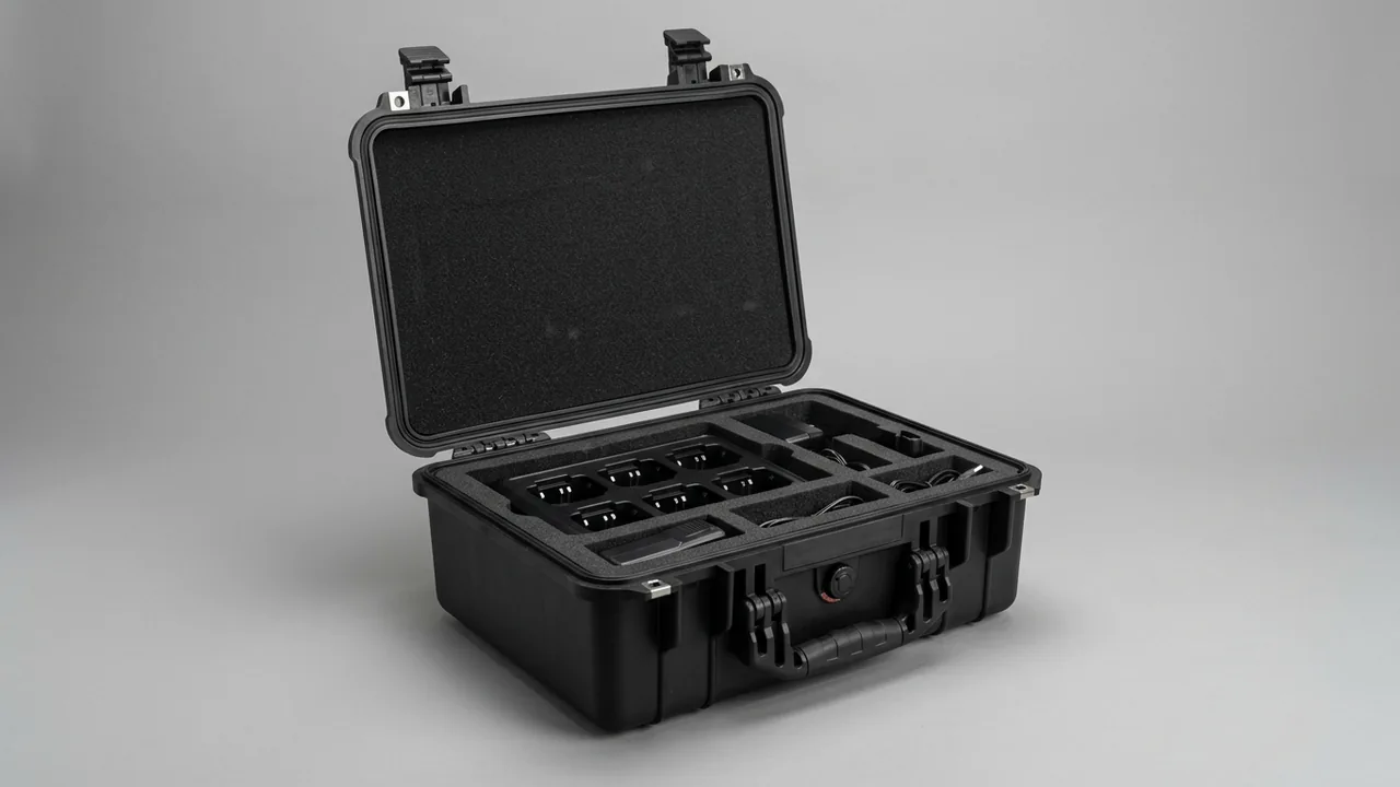
A dam gate component case has one job: to keep hoists, stainless seal parts, leaf rollers and embedded parts in the same condition they left the works, between dispatch and installation. That means no corrosion on a passivated face, no permanent set in a long slender member, and no loss of elasticity in a rubber seal. The core conclusion is that hydro gate components need a combination of a low-absorption case shell, liners zoned by material rather than by function, evenly spaced anti-deflection supports, and vapour phase rust prevention with humidity indication, because stainless passivated faces, rubber seals and long members each carry a different and incompatible requirement. Water projects routinely store equipment for months in a riverside yard and then handle it near an impoundment, so this window, not the journey itself, is where packaging is most often under-specified and where rework is most expensive.
Gate components differ from general machinery because they face three slow-acting forms of damage at once. The first is electrochemical corrosion. A gate spends its life in contact with water, with a splash and wet-dry band above the waterline and continuous immersion below it; when carbon steel and stainless steel sit in one crate, galvanic coupling adds to the problem, and once a stainless surface is contaminated by free iron, pitting nucleates within weeks. The second is deflection in long members. Hoist screw stems, gate slot guide rails and reverse rails are long, slender, and easily bent past their elastic limit if stacked flat with widely spaced support, and a bent stem cannot seat against the gate slot. The third is ageing of rubber seals. Ozone, ultraviolet light, heat and sustained squeeze all harden, crack or permanently deform rubber, and seal performance depends entirely on compression recovery, so a seal that has lost its spring cannot stop water. This guide works through each component family with practical parameters and acceptance criteria, and is written for design institutes, hoist manufacturers and hydro installation contractors.
Table of Contents
- Transport Risk Profile and Case Selection Rules for Hydro Gate Components
- Case Protection Design for Prolonged Damp and Immersed Service
- Passivation-Surface Protection for Stainless Seal Components
- Ageing-Safe Packing for Rubber Seals and Seal Retaining Plates
- Securing Winch Hoist Drums, Gearboxes and Limit Devices
- Bending and Coating Protection for Hydraulic Hoist Cylinder Rods
- Deflection Support for Screw Hoist Stems and Long Members
- Preventing Brinelling on Leaf Rollers, Main Wheels and Slide Blocks
- Long Straight Embedded Parts and Guide Rails in Transit
- Sealing, Damp Control and Salt Spray Testing
- Cavity Zoning: Separating Rubber, Stainless and Carbon Steel
- Unloading, Storage and Reassembly On Site
- FAQ
- Conclusion and Further Reading
Transport Risk Profile and Case Selection Rules for Hydro Gate Components
Drawing the boundary between what goes into a case and what does not is where hydro projects most often go wrong. The gate leaf itself is a large welded steel structure whose section frequently exceeds what any case can carry, and it travels on purpose-made saddles, bearers and lashing systems rather than in a box. Four families, by contrast, genuinely deserve a dedicated case because they are high value, easily damaged, and need to be managed as matched sets: the machined parts of a hoist, meaning drum assemblies, gearboxes, brakes, limit devices and hydraulic stations; stainless seal base plates, retaining plates and stainless fasteners; the main wheel, side wheel and reverse wheel assemblies with their slide blocks; and the small parts of the embedded set, including splice plates, connection pieces and anchor bolt groups. Putting all four families into one crate may look like a saving, but it introduces corrosion, cross-contamination and retrieval chaos simultaneously.
Three rules govern case selection. The first is zone by material, not by function; stainless and carbon steel parts must be physically separated, because rust debris and free iron from carbon steel are the direct cause of pitting on stainless, and a function-based layout usually breaks this rule. The second is distribute support according to stiffness; long members need evenly spaced supports to control deflection, bodies of revolution need curved saddles to control contact stress, and thin plates need vertical slots to hold flatness, and these three support types are not interchangeable. The third is set the corrosion protection level from the storage period, not from the delivery journey, because the gap between factory dispatch and gate installation is often three to twelve months in an open or semi-open yard, subject to the wet season and to river humidity. The priority of these three rules sits above appearance and unit price, because a violation cannot be solved by buying a different case.
A fast way to test whether a proposal is competent: ask what separates the stainless cavity from the carbon steel cavity, and what support pitch is used along a long member. If neither question gets a number, the proposal is probably generic packaging with a new name.
Case Protection Design for Prolonged Damp and Immersed Service
A dam gate case faces a continuous moisture source rather than occasional rain, so its logic differs from that of a simple waterproof box: it must exclude outside water and also manage the humidity of the internal microclimate. External water appears as spray and rain during riverside handling, as standing water in the yard, and as condensation on the shell during day-night temperature swings. Internal moisture comes from timber, paper buffers and rubber parts absorbing and releasing water, and from air that is breathed in and out as temperature changes. These two directions need separate treatment. Sealing alone, without internal humidity management, tends to create a stable and surprisingly humid microclimate during long storage.
Four structural actions matter. First, no untreated timber should carry structural load, because wood is both a moisture reservoir and a corrosion source; where hardwood blocking is unavoidable, use a controlled moisture content with anti-fungal treatment and never let it touch stainless parts. Second, the seal must survive repeated opening and abrasive grit, so use a double-pass arrangement with a sand relief step that lets grains escape rather than a single flat strip that a trapped grain can lift. Third, fit a breathable pressure equalisation element with a hydrophobic membrane so that temperature-driven differentials bleed away slowly instead of levering the gasket open or drawing moist air in, with the selection logic described in case pressure equalisation valves. Fourth, ensure no unreachable low point exists inside the shell by putting a drain plug at the base so the cavity can be washed, dried and resealed.
Humidity management follows three further actions. First, limit hygroscopic material inside sealed cavities; paper labels, ordinary board and low-density foam should be moved out. Second, apply a vapour phase corrosion inhibitor (VCI) system: carbon steel parts, fasteners and machined faces respond well to chloride-free and sulphur-free VCI film or emitters, which adsorb onto metal surfaces as a protective layer with a typical stated protection period of 12 to 24 months. VCI materials must not be allowed to touch stainless passivated faces or share a cavity with rubber seals, because compatibility with rubber is a known risk. Third, use humidity indicator cards to create a readable acceptance record, with colour bands from 10 to 60 percent. The sealing target is to hold internal relative humidity below 45 percent, or to keep the internal dew point more than 5 K below the lowest expected ambient temperature, dosing desiccant against free cavity volume and taking the upper figure in humid regions.
Where cases will sit in a riverside yard through several wet seasons, the shell itself deserves weather protection: external fasteners in stainless or plated finish, and a UV and low-temperature resistant polymer compound, so that the case does not fail before the components inside it ever run. If one batch of cases will be reused across contracts, write structural life and gasket replacement intervals into the technical requirement, using the criteria in protective case service life assessment.
Passivation-Surface Protection for Stainless Seal Components
Stainless steel resists corrosion because of a very thin, dense passive film, and that film has two enemies: free iron contamination and concentrated chloride. The damage done to stainless parts in transit is rarely visible rust; it is contamination that seeds pitting later. Carbon steel lifting gear, carbon steel pallets, ordinary steel strapping, and packaging materials previously exposed to iron swarf all deposit iron ions on the stainless surface, which then forms micro-cells in damp service and produces needle pitting within weeks. Stainless seal parts therefore belong to a cleanliness standard for clean components, not a general metal parts standard.
Four layers of protection apply. The first is contact material: every saddle, slot, strap and sling that touches stainless should be stainless, polyurethane or engineering plastic. Where a carbon steel sling is unavoidable, interpose a soft barrier and never allow a carbon steel item to slide across a stainless face. The second is isolation material: wrapping paper should be chloride-free, sulphur-free neutral paper or a dedicated stainless interleaving, and chloride-bearing plastic film should never be used over sheet or tubular stainless, because chloride concentrates in condensate beneath the film and drives pitting; polyethylene is acceptable as a separator as long as long closed gaps where liquid can collect are avoided. The third is physical protection of the passivated face: sealing faces, machined grooves and bolt hole edges get neutral film or soft padding so that they cannot knock against one another, since a scratch breaks the passive film and becomes a corrosion origin. The fourth is traceable contamination testing: on high cleanliness projects, an iron ion test using potassium ferrocyanide can be applied to sample surfaces on arrival, and a blue colour reaction indicates free iron contamination requiring re-pickling and passivation before installation.
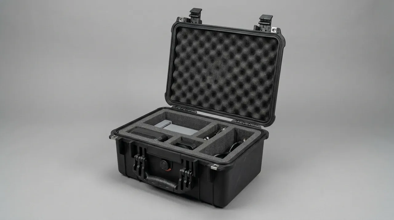
Orientation matters as much as material. Seal base plates and retaining plates are usually long, thin and flatness-critical, so stacking them horizontally makes the lower plates carry the upper ones and deflect permanently. They belong in vertical slots, pitched at plate thickness plus 3 to 5 mm, with soft material at the slot base so the plate is supported at its edges rather than across its face. Plates longer than about 2 m need proportionally more slots to avoid sagging in the middle. Stainless fasteners, bolts, nuts and washers should be compartmented by size as complete sets, never mixed with carbon steel fasteners, which invites substitution on site and the galvanic corrosion that follows. For how chloride-rich environments change the material isolation logic, desalination plant component cases is a useful parallel.
Ageing-Safe Packing for Rubber Seals and Seal Retaining Plates
A rubber water seal works through compression recovery rather than hardness alone, so packaging has to protect elasticity, not shape. Waterstop strips, P-profile seal rubber, and top, side and bottom seal sections age along four paths at once: ozone attack produces cracks perpendicular to the direction of tensile stress on a stretched surface; ultraviolet exposure powders and then deepens into the compound; heat and low temperature change compression set behaviour; and sustained squeeze or hanging under tension produces permanent deformation. Transport and storage can trigger all four together, particularly in a truck bed, under a container roof, or in an open yard where heat, ultraviolet light and ozone overlap.
The practical storage and packing requirements are as follows. Waterstop should be coiled and stored flat, with a coil inner diameter that is not too small, conventionally at least 300 mm, so that the rubber is not held under long-term bending stress. Hanging from hooks or stretching to shape is prohibited, as is stacking heavy items on top. Wrapping should be light-blocking; a dark polyethylene or aluminium laminate film blocks both ultraviolet light and ozone contact, and chloride-releasing or plasticiser-bearing materials must never share a cavity with stainless parts. Storage temperature is conventionally held between 10 and 25 degrees Celsius, and the case should be kept away from welding areas, electric motors and switchgear, which are ozone sources. This last point is frequently ignored during gate installation, when seals are laid out beside welding activity while waiting to be fitted.
Retaining plates and stainless bolts are metal items and follow the stainless rules, but their compatibility with the rubber matters too. Thread compounds and temporary rust preventive oils must not be chosen from formulations that migrate into rubber and cause swelling; if a coating is required, wipe it off before the plate contacts the seal. Inside the case, keep the rubber cavity and the stainless cavity apart, using a rigid divider and soft packing to create two microclimates, so that the rubber does not absorb rust preventive volatiles and the metal does not pick up plasticiser from seal packaging. Add a storage instruction label stating the permitted temperature range, the light-blocking requirement and the maximum sealed storage period; it is the simplest packaging improvement with the most direct benefit on a hydro site.
Securing Winch Hoist Drums, Gearboxes and Limit Devices
Among winch hoist assemblies, the drum group, gearbox, brake and limit device are the classic high-value machined items, and their transport priority is that concentricity and mating faces must survive intact. A drum assembly includes the drum shell, shaft, bearing housings and a geared coupling, and once vibration or impact shifts the relationship between bearing housing and drum axis, the wire rope will wear against the drum groove on installation. The drum group should therefore be supported through the bearing housing base or a dedicated mounting face, not through the drum's cylindrical surface; a curved saddle limits rolling but does not carry the primary load. Drum grooves are machined surfaces, and any scratch becomes a rope wear source, so the grooved region gets a soft sleeve or a narrow interleaving film.
Gearboxes and brakes need protection at the shaft extensions and jointing faces. Shaft extensions get a sleeve with an inner diameter 2 to 4 mm larger than the shaft and a soft liner, long enough to cover the extension and overhang slightly. Jointing faces get soft shields so that an external blow cannot land on the sealing surface. Brake shoes and the brake wheel must stay free of oil, so their packing must not contain migrating grease, and a divider should separate them from lubricated gearbox areas when both travel in one case. Limit devices, position indicators and encoders, being a mix of electrical and precision mechanical parts, belong in an independent sealed cavity with desiccant, no paper or tape inside, capped connectors, and an external label stating orientation limits. The zoning logic for drums and brakes matches the arrangement used in hoist component cases.
For consignments shipped as complete sets, zoners should group by installation unit rather than by part category. Putting the brake, coupling and limit device of one hoist into one numbered cavity group lets the site draw and return the whole group, which sharply reduces mis-fitting and loss. For lifting and lashing practice on bodies of revolution, winch parts cases covers the drum handling sequence.
Bending and Coating Protection for Hydraulic Hoist Cylinder Rods
Hydraulic hoist cylinders in hydro projects are long-stroke, large-bore slender compression members, and the transport risk concentrates on the piston rod. The rod surface is chrome or ceramic coated with extremely low roughness, so any scratch breaks coating continuity and, in a damp environment, opens a corrosion path that then creeps along the coating interface and is very expensive to repair. Straightness matters just as much: long-stroke cylinders hold tight limits on rod straightness and barrel coaxiality, and a rod bent by a side load in transit will cause eccentric wear and early seal failure after assembly.
Three issues need solving. First, attitude: a long-stroke cylinder should travel with the rod retracted wherever the design allows. If it cannot be retracted, the extended section needs continuous support rather than a cantilever, with a support roughly every 1.5 m or closer using soft polyurethane V-blocks or cradles so the rod never sees a concentrated load. Second, coating protection: the exposed rod section gets a sleeve or soft wrap whose inner face must be clean and free of grit, because grit trapped inside a sleeve grinds the coating under vibration and does more harm than leaving the rod bare; wipe the rod and confirm it is free of oil and debris before fitting. Third, lifting: sling the cylinder with wide belts around the barrel ends or with dedicated lugs, never with wire rope or chain around the barrel or rod, and never sling from the rod end thread or eye, which is the weakest connection point.
Hydraulic cleanliness and moisture exclusion apply here as well, with a hydro-specific twist: ports on a cylinder that are exposed to river humidity during transit will develop rust inside the bore, so closure must be complete, with matched cover plates on flanged ports and threaded plugs in threaded ports, each backed by a plastic cap so handling cannot dislodge it. Where cylinders and hydraulic stations ship in one consignment, use separate cavities and give the station a dedicated cavity with desiccant. When cylinders travel with gate leaf sections, keep loose items that could generate metal swarf out of the cylinder cavity. Barrel port closure practice is described in hydraulic lift component cases.
Deflection Support for Screw Hoist Stems and Long Members
The screw stem of a screw hoist has the highest slenderness ratio of any hydro component, commonly 3 to 8 m long and a few tens to a hundred millimetres in diameter, and its transport protection reduces to a single governing parameter: deflection. Neither the threaded section nor the ground guide section may take a permanent set, because a bent stem loads the thread and nut unevenly and shows up as abnormally high opening torque on site and accelerated thread wear. Many projects lay the stem in a truck bed on a few hardwood blocks, which looks supported but leaves excessive span; the dynamic amplification of a vehicle crossing a rough joint then pushes mid-span bending moment far beyond a static estimate.
Support should be designed against a deflection limit rather than intuition. Practically, supports are placed at even pitch with spacing no greater than one eighth to one tenth of the stem length, and mid-span deflection under self weight combined with dynamic amplification is checked against an allowable value conventionally around one part in 1500 of length. Support blocks are soft polyurethane or hardwood with a cloth facing, shaped as a V or cradle to stop the stem rolling, and they must never sit on the threaded section; they bear on plain stem sections or on a purpose-made shoulder. For multi-point lifting, two lifting points set at roughly 0.2 of the length from each end give the lowest maximum bending moment from self weight, and longer stems need a spreader beam or additional points to avoid a sagging middle with raised ends. Never sling directly around the thread; use wide belts with sleeves, or fit a protective tube over the threaded section before lifting.
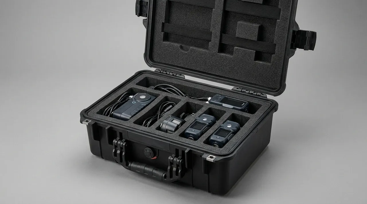
Thread protection ranks with support. The trapezoidal thread section needs a protector matched to the thread form, and the stem must not touch carbon steel guide rails or reverse rails. Connection heads, pins and thrust bearing housings at the stem ends belong in separate compartments with pins and retaining rings bagged as numbered sets. After unloading, do not release the supports until the storage location offers equivalent support; transfer the whole assembly, and avoid the common shortcut of leaning a stem against a wall, which bends it again.
Preventing Brinelling on Leaf Rollers, Main Wheels and Slide Blocks
Gate leaf rollers are precision-fit, heavily loaded components. Main wheels, side wheels and reverse wheels are usually cast or forged with bearings or bushes, and their fits and raceways are highly sensitive to impact. One mechanism deserves emphasis in transport: fretting and false brinelling. When a roller stands still under sustained vibration, the contact point between rolling element and raceway undergoes tiny reciprocating slip, the oil film breaks down, metal touches metal, and a depression forms at the spacing of the rolling elements. This damage is often invisible at goods-in, yet produces abnormal vibration, noise and service life after assembly. The cure is to break the vibration path and remove sustained static load, not merely to add foam thickness.
Three measures follow. First, unload: the roller assembly should be carried through its shaft ends or mounting flange so the outer diameter bears no weight; where the design makes this impossible, shorten the storage period and rotate the roller periodically to change the contact position. Second, isolate: the cavity liner should have low dynamic stiffness to reduce transmissibility, while still touching the component without preload so that no rigid impact path forms, and where heavy carbon steel parts travel in the same case, keep the roller cavity well away with a rigid divider between. Third, protect against corrosion: bearing seals and oil seal lips must not be exposed to solvents or alkaline cleaners, and where VCI is used inside the case its compatibility with the bearing grease must be confirmed, because some VCI constituents diffuse into grease and alter its behaviour.
Slide blocks are usually composite or polytetrafluoroethylene-faced, and their sliding faces must not be scratched or contaminated. Store them standing on a non-sliding face with the sliding face inward, separated by lint-free cloth or polyethylene film, and never stacked. Where the block body is carbon steel, isolate it from the stainless cavity and apply a removable temporary rust preventive, cleaned off before installation. Number the roller sets, slide blocks and fasteners so they match the gate leaf sections, which lets the site assemble in sequence. For combined protection of bearings and seals in damp conditions, see fire pump component cases.
Long Straight Embedded Parts and Guide Rails in Transit
The embedded set includes main rails, reverse rails, side rails, the sill and the lintel, and these parts set the installation datum for the whole gate. They are long and straight with machining confined to a few mating faces that determine whether the leaf travels freely. Two protection priorities apply: against bending, and against knocks on machined faces. Anti-bending practice follows the logic used for stems, but because embedded parts are welded fabrications with relatively low bending stiffness, support pitch should be tighter, conventionally no more than one eighth of the length, with an extra support near each splice end so the ends do not droop. Stacking should be avoided; where stacking is unavoidable, continuous dunnage should be placed between layers and aligned vertically so load passes straight down rather than creating a local fold between layers.
For lifting, single-point lifts are unacceptable on long straight parts. A single point creates high local stress and lets both ends sag, which can leave residual deformation. With two or more points, place them about 0.2 of the length from each end, keep sling angles within 60 degrees to limit the additional compressive component, and fit soft sleeves or dedicated lifting clamps where the sling meets a machined face. On parts with stainless cladding or a finished protective coating, slings and straps must not bear directly on the coating; use non-absorbent, non-shedding soft packing at the contact points, so the packing cannot absorb water and create a long-term damp contact patch that blisters the coating.
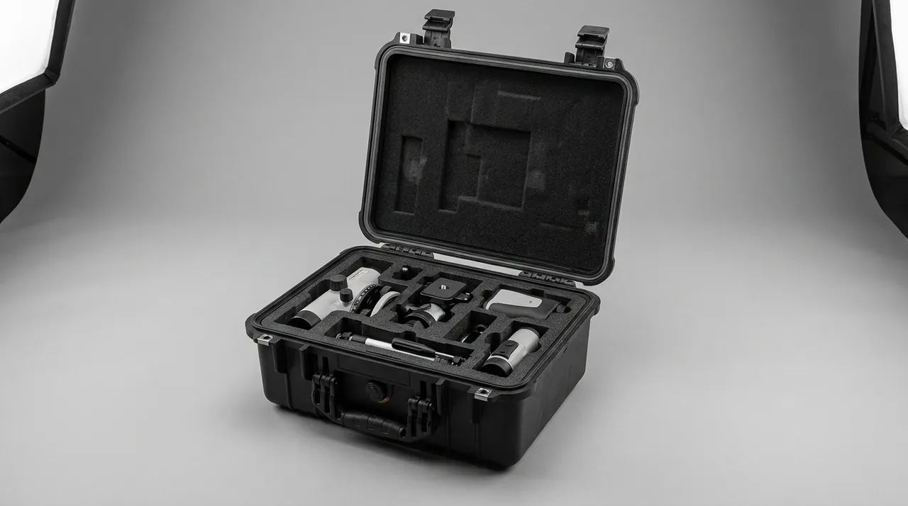
Machined faces need their own protection design. The working faces of main and reverse rails are machined to tight flatness, and any dent leaves a local gap after installation. Protect them with peelable film, or design a continuous support band in the liner that follows the working face direction so the face bears on continuous soft support rather than point contacts. Bolt holes, anchor studs and weld preparations all need temporary protection: plastic plugs or wrapped film in bolt holes, and non-metallic pads taped over weld preparations, so that transport damage does not turn into on-site re-machining. Loose splice plates and bolt groups belong in compartments numbered to match the installation sequence, which lets the site work section by section instead of rummaging through the case and scuffing coatings.
Sealing, Damp Control and Salt Spray Testing
Protection performance has to be demonstrated by test rather than asserted. Testing covers two categories: mechanical transport behaviour, which answers whether parts will shift or deform, and corrosion behaviour, which answers whether they will rust during storage. Mechanical methods come from the GB/T 4857 series, ISTA protocols and ASTM D4169; corrosion work centres on salt spray and damp heat, with neutral salt spray defined in GB/T 10125, typically at 5 percent sodium chloride solution, 35 degrees Celsius cabinet temperature and continuous spray, evaluated through coating blistering, corrosion creep from a scribe and cross-cut adhesion change. Environmental test method standards such as MIL-STD-810H serve here only as a reference for defining temperature, humidity and vibration profiles; they do not constitute any military certification.
| Test item | Method basis | Example parameters | Criteria and observation points |
|---|---|---|---|
| --- | --- | --- | --- |
| Neutral salt spray | GB/T 10125 | 5 percent NaCl, 35 C, graded durations | No blistering or flaking, scribe creep within allowance |
| Damp heat cycling | GB/T 4857 humidity items | Temperature cycling plus high humidity phase | Humidity card within limit, no condensation pooling |
| Random vibration | GB/T 4857.23 or ISTA sequence | PSD from route spectrum, commonly 0.5 to 2 h | No residual deflection in long members, supports unmoved |
| Incline impact and drop | ISTA 3E / GB/T 4857.5 | Selected by mass grade | No cracking at lifting points, no dents on machined faces |
| Sealing verification | IEC 60529 / GB/T 4208 | IPX7 short immersion condition | No internal water traces, no grit in seal groove |
| VCI protection period | Supplier validation data | Stated emitter protection period | Sampled metal faces rust free at end of storage |
Observation points should be planned before testing starts. Mark both ends and mid-span of long members to detect residual deflection; place stainless and carbon steel coupons in their respective cavities to confirm that isolation works; place humidity indicator cards where they can be read without opening. After the programme, inspect three specific things: whether support blocks have crushed and deformed, whether VCI material has contacted rubber parts, and whether grit has embedded in the seal groove. For test execution order see ISTA transport testing procedure, for domestic acceptance mapping see GB/T 4857 transport packaging testing, and for building sequences from distribution cycles see ASTM D4169 distribution cycle testing. Case and document marking should follow GB/T 191 and GB/T 13384.
Cavity Zoning: Separating Rubber, Stainless and Carbon Steel
Liner design for a dam gate case is really the implementation of a materials compatibility matrix. Within one microclimate, the effect components have on each other usually matters more than the outside environment: carbon steel rust debris contaminates stainless, rust preventive volatiles swell rubber, VCI constituents affect bearing grease, and chloride-bearing packaging drives pitting in damp conditions. Zoning should therefore be driven by material and chemical sensitivity, not by size. The table below states the isolation requirement for each main family and can be used directly as liner design input.
| Component family | Key sensitivity | Must be separated from | Recommended contact materials | Prohibited contact materials |
|---|---|---|---|---|
| --- | --- | --- | --- | --- |
| Stainless seal plates, retaining plates, fasteners | Free iron, chloride concentration | Carbon steel parts, carbon steel slings and straps | Neutral paper, chloride-free interleaving, polyurethane blocks | Chloride-bearing film, ordinary steel strapping, iron-contaminated board |
| Waterstop strips, P-profile seals | Ozone, ultraviolet, ester and plasticiser migration | VCI materials, greasy packaging | Dark PE film, aluminium laminate, light-blocking liner | Plasticiser-bearing film, PVC, oiled rust cloth |
| Rollers, slide blocks, bearings | Fretting, grease dilution | Heavy carbon steel parts, loose small items | Low-outgassing moulded liner, lint-free cloth | Hygroscopic fibrous material, friable foam |
| Stems, embedded parts, long members | Self-weight deflection, coating scuffing | Mutual stacking, sharp-edged parts | Rigid skeleton plus soft cradle blocks | Direct steel strapping, unsupported multilayer stacking |
| Electrical and limit devices | Damp insulation loss | Metal swarf and cleaning fluid | Independent sealed cavity plus desiccant | Paper buffers, uncapped connectors |
On material selection, closed-cell PE, IXPE and low-outgassing moulded EVA work well as separation and cushioning layers; polyurethane blocks suit the load-bearing supports for long members and revolving parts; and rigid PP or aluminium skeletons establish cavity boundaries and load paths. What to avoid is one foam throughout the case: a cavity holding both an 8 m stem and a precision limit device cannot satisfy low dynamic stiffness and high compressive capacity with a single material. Layout should put heavy items low, long items along the long axis, and precision and stainless items in independent upper cavities, with the packing list matching the cavity numbers. Material comparison data appears in protective case foam material comparison; where models change between contracts, keep the shell skeleton and rigid dividers and change only liner modules, with tooling and liner cost structure covered in custom case mould cost analysis and sampling practice in custom foam inserts guide and EVA foam insert custom process. JUNZHIJIA normally splits cavities from the materials matrix first, derives support pitch from the deflection allowance for long members second, and fixes the shell skeleton and lifting points last, which keeps late changes to a minimum.
Unloading, Storage and Reassembly On Site
Site conditions on a hydro project are usually worse than in the factory: the yard borders the river, the surface is backfill, lifting depends on a crawler or truck crane, and storage spans the wet season. Unloading and storage therefore need a written procedure rather than site improvisation. The first unloading rule is do not release the supports until the case or cradle is on the ground and the storage position offers equivalent support. Where transfer is necessary, move the whole case or use a spreader beam; never sling embedded parts or stems with wire rope.
Storage actions include: standing cases on level, draining ground so the base is not permanently wet; keeping the long axis level so a sloped position cannot load one side of a long member; avoiding stacking, or confirming the rated stacking capacity and aligning dunnage when stacking is unavoidable; reading the humidity card on a schedule for long-stored cases, replacing desiccant when over limit and recording the result; and keeping the case away from welding areas, switchgear and heat sources to protect rubber and electrical parts. Near a gate chamber, humidity is high and ventilation poor, so a simple rain shelter with vents is worth providing if possible, to keep the shell dry and reduce continuous damp contact with the gasket.
Reassembly needs process control too. On opening, count and register parts against cavity numbers, and return protective sleeves, hole plugs, blanks and caps to their numbered positions rather than piling them together. While moving stainless parts to the gate, keep using non-metallic or isolated tools so that free iron is not introduced in the last step. Inspect rubber seals for hardening, cracking and permanent deformation before installation, and do not install anything that fails. Check long members for straightness before fitting; if residual bend exists, correct it on the ground, because forcing it straight during installation builds locked-in stress inside the gate slot. Cleaning steps are covered in how to clean a protective case, with attention to seal grooves, the drain plug and the breathing membrane. Where storage exceeds the agreed period, re-verify VCI condition and stainless surface contamination before installation.
FAQ
Q: Can the gate leaf itself be shipped in a protective case?
A: Generally it cannot, and it should not be attempted. A gate leaf is a large steel section weighing from several tonnes to several tens of tonnes, exceeding the capacity of any normal case both in size and in handling, and it travels on purpose-made saddles and bearers with multi-point lashing. What a protective case carries is the four families that need set control and chemical isolation: the drum group, gearbox, brake, limit device and hydraulic station of the hoist; stainless seal base plates, retaining plates and fasteners; the main, side and reverse wheel assemblies with their slide blocks; and the small parts of the embedded set, including splice plates and anchor bolt groups. Packing these into a case moves corrosion, contamination and retrieval risk back into the factory where it can be controlled. If a project wants case-style protection for leaf sections as well, the practical compromise is a removable local shield over the precision mating faces and seal plate mounting faces, shipped with the section, while the section itself still travels on a cradle.
Q: Why must stainless seal parts never share a case with carbon steel items?
A: Because carbon steel acts as a contamination source rather than a compatible neighbour. Stainless resistance depends on a dense passive film, and that film is vulnerable to free iron. Rust debris from carbon steel, scratches from carbon steel lifting gear and iron ions left by ordinary steel strapping all create contaminated spots on the stainless surface, and in damp or chloride-bearing service these spots form micro-cells with the parent metal that develop into needle pitting within weeks. Where the two materials touch directly in the presence of an electrolyte, galvanic corrosion compounds the effect, with carbon steel acting as the anode and its corrosion products further contaminating the stainless. Zoning should therefore begin with material, not function or size. Practical measures include stainless, polyurethane or engineering plastic for all saddles, slots and straps that touch stainless parts; chloride-free and sulphur-free neutral wrapping paper; and iron ion colour testing on arrival for high cleanliness projects, with re-pickling and passivation if contamination is found.
Q: Under what conditions does a rubber water seal lose its ability to stop water?
A: The governing mechanism is loss of elasticity, driven by four paths acting together. Ozone preferentially attacks stretched rubber surfaces and creates fine cracks perpendicular to the stress direction. Ultraviolet light powders the surface and then penetrates deeper. Heat accelerates changes in the vulcanised network and migration of plasticisers, while low temperature hardens the compound and slows recovery. Sustained squeeze or hanging under tension produces permanent compression set. Seal performance depends on compression recovery, so once recovery is insufficient the contact pressure under the gate is too low and leakage begins. Protection means coiling and storing flat with a coil inner diameter of at least 300 mm, never hanging or stretching to shape, using light-blocking wrap and avoiding chloride-releasing or plasticiser-bearing film, holding storage temperature between about 10 and 25 degrees Celsius, and keeping the case away from welding areas, motors and switchgear that generate ozone. Inspect for hardening, cracking and permanent deformation before installation, and reject anything that fails.
Q: What is the most common transport problem with a screw hoist stem?
A: Permanent deflection, and it usually only surfaces during installation. A stem has a high slenderness ratio, and laying it in a truck bed on a few hardwood blocks looks like support while leaving excessive span. When the vehicle crosses a rough joint, dynamic amplification pushes mid-span moment well beyond a static estimate; once the elastic limit is exceeded, a permanent bend remains. A bent stem loads the thread and nut unevenly, which shows up as abnormally high opening torque and accelerated thread wear, and often ends in replacing the whole stem. Protection means even support pitch no greater than one eighth to one tenth of stem length, soft polyurethane or cloth-faced hardwood blocks shaped as a V to prevent rolling, no support placed on the threaded section, and two lifting points set about 0.2 of the length from each end so self-weight moment is minimised. Never sling directly around the thread. After unloading, confirm the storage position offers equivalent support before releasing anything.
Q: Should a hydraulic hoist cylinder travel with the piston rod retracted or extended?
A: Retracted is preferable, because the rod then sits inside the barrel where it sees almost no side load and no coating damage risk. If the design does not allow retraction, the extended section needs continuous support rather than cantilever load, with supports every 1.5 m or closer using soft polyurethane V-blocks or cradles to avoid concentrated loading. Coating protection matters just as much: the exposed rod section should be sleeved or wrapped in soft material, but the rod must be wiped clean and confirmed free of grit before the sleeve goes on, because grit trapped inside a sleeve grinds the coating under vibration and does more damage than no sleeve at all. Lifting should use wide belts around the barrel ends or dedicated lugs; wire rope or chain around the barrel or rod is prohibited, and slinging from the rod end thread or eye is prohibited because that is the weakest connection point. Verify all port blanks and plugs before dispatch, and re-check them before lifting on arrival.
Q: What counts as adequate protection for machined faces on embedded gate slot parts?
A: The aim is to eliminate both knocks and point-contact impressions, which means solving the contact method and the contact material together. For contact method, the working face should bear downward on a continuous soft support band rather than on a few discrete points; if the working face must be oriented sideways, build a continuous mating surface into the liner that follows the direction of the face and apply peelable film over the surface. When stacking is unavoidable, place continuous dunnage between layers with vertical alignment so load passes straight down rather than creating a local fold between layers. For contact material, any pad touching a finished coating or stainless cladding should be non-absorbent and non-shedding, so it cannot hold water against the coating and cause blistering. Bolt holes get plastic plugs or wrapped film, weld preparations get non-metallic pads, and slings and straps must never bear on coatings or cladding. Loose splice plates and bolt groups go into compartments numbered to the installation sequence.
Q: Why put a humidity indicator card in a hydro component case instead of relying on desiccant?
A: Because desiccant failure is invisible, while a humidity card turns the internal microclimate into a readable acceptance record. Once desiccant is saturated its appearance barely changes, so the site cannot judge whether it still works, and opening a case on visual inspection alone may mean the components have already spent the whole wet season in high humidity. Indicator cards show colour bands from 10 to 60 percent, so the decision to open can be made after an objective reading, and components can be moved to a dry area before the liner is stripped if humidity is over limit. The engineering target is internal relative humidity below 45 percent, or an internal dew point more than 5 K below the lowest expected ambient temperature, with desiccant dosed against free cavity volume and the upper figure used in humid regions. For long storage, provide a replaceable desiccant cartridge and a viewing window, since opening the case to check humidity is itself a common way of letting moisture in. Record card colour photographs as traceable acceptance evidence.
Q: If a case passes a salt spray test, does that prove components will not corrode in service?
A: Not directly. Salt spray provides a comparative screening basis rather than a service life prediction. Neutral salt spray per GB/T 10125 is commonly run at 5 percent sodium chloride, 35 degrees Celsius and continuous spray, which intensifies the action of chloride and oxygen and accelerates coating defect exposure and pitting tendency in stainless, but a real gate environment also includes wet-dry cycling, flowing water scour, biological growth, silt abrasion and occasional water quality variation, none of which a salt spray cabinet reproduces faithfully. The correct role for this test is to compare protection and isolation options, for example the difference in corrosion between stainless coupons with and without free iron contamination over the same duration. Where a project sits in a coastal estuary or high chloride water, select a molybdenum-bearing stainless such as 316L at the material stage and avoid closed gaps where liquid can collect. After testing, inspect both the humidity card status in each cavity and the metal coupon surfaces, because only the combination shows whether the scheme works.
Conclusion and Further Reading
Separate the materials, prop the long parts, control the moisture, and block the knocks. Zoned cavities stop galvanic contamination, even support pitch controls deflection, and humidity cards carry a component through a wet season. JUNZHIJIA supplies material-zoned liners and matched seals.
Related Reading