


Most transit damage to hydraulic lift platforms does not happen in service. It happens on the way to the installation site. A scored piston rod hard-chrome layer becomes an early oil leak. A cylinder barrel pressed into an oval section causes creeping and juddering. A power-unit reservoir dented by impact causes poor oil suction and noise. A damaged valve-block sealing face causes internal leakage and unstable pressure. A control box exposed to moisture causes insulation resistance to drop. These faults all surface during commissioning, when liability is hard to assign and rework is expensive. The conclusion is clear: a hydraulic cylinder is a precision hydraulic actuator, and a power unit is an integrated oil-and-electrics assembly. Both require an outer case with separated-cavity location, cleanliness control, moisture sealing, and vibration-damped support - not a crate stuffed with filler, not stretch wrap, and not bare parts tied together.
Three characteristics set cylinders and power units apart. In the trade this packaging category is generally called a hydraulic lift case, subdivided by use into hydraulic cylinder cases and power unit cases, all brought under one numbering and traceability system for lifting equipment cases. The first is surface integrity. The piston rod's outer diameter is a hard-chrome-plated sliding fit surface whose roughness and roundness govern seal life. Any score or dent becomes the starting point of a leak and cannot be repaired on site. The second is internal cleanliness. A substantial share of hydraulic system failures originates from particulate contamination; once particles enter the oil and reach the clearances, they cause valve spool sticking, seal wear, and pump scoring, and contamination is often introduced at the packaging step. The third is compound sensitivity. A power unit is usually an integrated assembly of reservoir, motor, pump, valve block, and control box, exposed simultaneously to mechanical shock, moisture, corrosion, and electrostatic discharge.
This article is written for lift platform manufacturers, hydraulic component suppliers, equipment rental companies, and project buyers. It sets out graded protection schemes for cylinders and power-unit components, insert and cleanliness design, standard validation methods, and on-site acceptance rules, and it explains the engineering capability behind custom inserts and OEM/ODM supply.
Table of Contents
- 1. Why Hydraulic Lift Platform Components Need a Dedicated Parts Case
- 2. Cylinder and Power-Unit Component List and Protection Class
- 3. Failure Modes: Rod Scoring, Barrel Deformation, Power-Unit Contamination and Valve Sticking
- 4. Size and Weight Boundaries: Packing Cylinders, Power Units and Structural Parts
- 5. Heavy-Duty Case Structure and Material Selection for Long-Stroke Cylinders
- 6. Insert Design: Contoured Slots, Full Coverage and Isolated Cavities
- 7. Protecting Hydraulic Lines, Fittings and Valve Assemblies
- 8. Protecting Electrical Parts: Control Boxes, Limit Switches and Sensors
- 9. Ingress Protection for Cylinder and Power-Unit Cases: IEC 60529 against GB/T 4208
- 10. Cleanliness and Rust Prevention: ISO 4406 and Particulate Control
- 11. Vibration Validation for Cylinder and Power-Unit Shipments: GB/T 4857 and ISTA
- 12. Stacking, Lifting and Centre-of-Gravity Control for Heavy Hydraulic Cases
- 13. Labelling, Traceability and Site Assembly Management for Hydraulic Parts
- 14. OEM/ODM Customization: Acceptance and Maintenance for Cylinder Cases
- Frequently Asked Questions
- Conclusion & Related Reading
1. Why Hydraulic Lift Platform Components Need a Dedicated Parts Case
A hydraulic lift platform is a classic combination of heavy load, precision, oil, and electrics. Its core components leave the factory already machined to demanding accuracy, and much of that accuracy is squandered at the packaging step.
A cylinder's precision lives on its surfaces. The value of a cylinder is not in the weight of steel but in the accuracy of the barrel bore, the piston rod outer diameter, and the mounting dimensions at both ends. Barrel bore roundness and straightness determine how evenly the piston and seals seat. The plating thickness, hardness, and roughness of the rod determine how fast the seal lip wears. Once the plating is scored, leakage is almost inevitable, and there is no on-site way to restore it.
A power unit is an integrated sensitive assembly. A compact hydraulic power unit usually integrates a reservoir, a plunger or gear pump, a drive motor, a relief valve, a solenoid directional valve, and a control box on one baseplate. Transit shock travels through the baseplate to the pump shaft and motor shaft, and can cause coupling misalignment, shaft extension deformation, or pump body cracking. Impact can dent the reservoir, affecting volume and suction. Moisture reduces motor insulation resistance.
Contamination is the most invisible killer in hydraulics. Wood dust from crates, foam debris, dust from cutting and grinding operations, and grit from the packing floor can all enter oil ports, fittings, or valve bodies. After assembly these particles circulate with the oil, progressively causing spool sticking, seal scoring, and pump wear. Such failures typically appear weeks to months after commissioning, are hard to trace, and are frequently misdiagnosed as product quality defects.
Hydraulic cylinders blur the liability boundary most. When a rod is scored or a barrel bore shows contamination after installation, supplier and buyer struggle to separate a machining defect from a transit scratch or an assembly injury. A standardised case with a signed opening-inspection record — rod plating, bore, and oil-port cleanliness logged at unpacking — turns that blurred boundary into a traceable chain of responsibility.
Key reminder: hydraulic component damage is cheap to prevent and expensive to reverse. The cost of reworking one piston rod, plus line downtime, usually exceeds the packaging investment for an entire batch of cylinders.
For a cylinder plant or a lift platform builder, the parts case plays one more role that is easily overlooked: reusable tooling. Collapse the bore bands and stroke steps into three to five case types, pair them with a swappable insert plate set, and a limited pool of cases covers the whole product range, so storage positions, handling gear, and inspection items all shrink with it. Reuse limits and discard criteria are covered in protective case service life and reuse years.
2. Cylinder and Power-Unit Component List and Protection Class
Protection priorities differ markedly between hydraulic lift components, so grade each item before packing.
| Component | Typical material / structure | Critical sensitivities | Recommended protection |
|---|---|---|---|
| --- | --- | --- | --- |
| Hydraulic cylinder (complete) | Barrel, piston rod, end clevises | Rod plating, barrel roundness, pin bores | Horizontal contoured slot + full rod sleeve |
| Piston rod (loose) | Hard-chrome-plated steel bar | Plating scores, bending | Dedicated long slot + full-length sleeve + multi-point soft support |
| Cylinder barrel (loose) | Cold-drawn seamless tube | Bore damage, ovalisation | End protection + horizontal half-round cradle |
| Hydraulic power unit | Reservoir, pump, motor, valves | Pump shaft, motor shaft, oil ports, insulation | Isolated cavity + damping pad + barrier bag |
| Compact power pack | Integrated baseplate | Mounting holes, terminal chamber | Baseplate location + port caps + desiccant |
| Valve block and manifold | Cast iron or aluminium body | Sealing faces, port threads | Isolated cavity + port plugs + anti-rust paper |
| Hydraulic hose and tube | Rubber or steel | Bend radius, fitting threads | Large-radius coiling + fitting sleeves |
| Accumulator | Pressure vessel | Charging valve, sealing face | Upright fixing + valve guard |
| Control box and board | Sheet-metal box, PCB | Moisture, ESD, shock | Barrier bag + ESD bag + damped support |
| Limit switch and sensor | Electronic component | Contacts, lens, cable | Small-parts box + ESD packaging |
| Scissor arm and linkage | Section steel, bent parts | Straightness, pin bores | Upright divided cavity + edge guards |
| Roller and slider | Alloy steel, engineering plastic | Rolling surface, mounting bore | Dedicated slot + protective film |
| Seals and oil seals | Rubber, PU | Deformation, ageing, oil | Flat compartments + light-blocking bag |
| Fasteners and pins | Alloy steel | Threads, fit surfaces | Compartment box + anti-rust paper |
The table shows that rod surface integrity and internal cleanliness are the two physical protection themes, while power-unit electrical insulation and valve sealing faces form the third.
3. Failure Modes: Rod Scoring, Barrel Deformation, Power-Unit Contamination and Valve Sticking
Piston rod plating scores and dents. Hard chrome is hard but limited in toughness. Contact with section-steel edges, pins, bolts, or the case wall produces scores, dents, and local spalling. A score breaks the seal lip contact and becomes a leak path. A dent creates a high spot that accelerates seal wear.
Piston rod bending. A piston rod is a slender bar, and long-stroke cylinders have a high length-to-diameter ratio with low bending stiffness. Shipped bare with an unsupported mid-span, or loaded at the ends or struck laterally, it acquires slight bending. Once out of tolerance, the cylinder creeps, wears unevenly, and leaks internally.
Barrel bore damage and ovalisation. The bore is a machined surface. Foreign matter or an end impact scores it. Stacking pressure or a drop impact ovalises the section. Once oval, the piston seal cannot seat evenly, producing internal leakage and unstable motion.
Power-unit oil port and valve sealing face damage. Port threads and valve mounting faces are sealing fits. Impact-damaged threads prevent a fitting from tightening. A scored sealing face leaks under high pressure. On site such damage can only be lapped or the valve body replaced.
Shock damage to pump and motor shafts. A power unit is heavy, and transit shock travels through the baseplate and coupling to the pump and motor shafts. Mild damage shows as noise and temperature rise; severe damage cracks the pump body or bends a shaft extension.
Electrical moisture ingress and insulation loss. Motor windings, control boards, and terminals are moisture sensitive. Sea freight and humid seasons drive insulation resistance down, and in severe cases cause trip-on-energise or corrosion of control boards.
Particulate contamination causing valve sticking. This is the most concealed failure mode. Once particles enter the clearance between spool and bore, the spool becomes sluggish or seizes, showing up as pressure fluctuation, incomplete movement, or no movement at all.
Seal deformation and ageing. Seals take a permanent set after prolonged compression, heat, or oil immersion. In transit, compression by heavy items or contact with sharp edges cuts them directly.
4. Size and Weight Boundaries: Packing Cylinders, Power Units and Structural Parts
Hydraulic lift platform components span an enormous range, from seals a few tens of millimetres across to cylinders several metres long and power units weighing hundreds of kilograms.
| Class | Typical characteristics | Unit weight | Packing strategy | Key risk |
|---|---|---|---|---|
| --- | --- | --- | --- | --- |
| Micro parts | Seals, pins, fittings | Under 5 kg | Compartment box inside a master case | Loss, mixing |
| Small parts | Sensors, switches, spools | 5-20 kg | Isolated cavity + soft liner | Impact, ESD |
| Medium parts | Valve assemblies, small power units | 20-100 kg | One-person carry case + location | Drop during handling |
| Large parts | Standard cylinders, medium power units | 100-500 kg | Wheeled heavy-duty case + lifting points | Unbalanced lift |
| Very large parts | Long-stroke cylinders, large power units | Over 500 kg | Base pallet case + multi-point lifting | Structural instability |
Three grading principles apply. First, grade by handling method: below 20 kg one person can carry, 20-50 kg needs two people or an aid, and above 50 kg requires lifting points or forklift pockets. Second, grade by stiffness: slender parts such as piston rods and linkages need multi-point support with spacing empirically within one third of part length to avoid first-mode bending resonance. Third, grade by value and sensitivity: power units, control boxes, and servo valves should be cased separately and never mixed with heavy or sharp items.
5. Heavy-Duty Case Structure and Material Selection for Long-Stroke Cylinders
The packing problem on a hydraulic lift platform is not weight alone. It is weight combined with length: a cylinder is a slender bar and a power unit is an off-centre mass, and one case often has to hold both. Material selection comes down to finding the intersection of rated load, bending stiffness, and case tare weight that hydraulic parts can tolerate.
| Case type | Body material | Rated unit load | Structural trait | Hydraulic lift parts it suits |
|---|---|---|---|---|
| --- | --- | --- | --- | --- |
| Glass-filled injection case | PA / PP + GF | Up to 80 kg | Thin wall, stable dimensions, tight assembly tolerance | Valve blocks, manifolds, small power packs |
| Standard rotomoulded case | LLDPE | Up to 250 kg | One-piece moulding, good low-temperature toughness | Standard cylinders, 63-125 mm bore |
| Long-part rotomoulded case | LLDPE with moulded-in ribs | Up to 300 kg | Longitudinal ribs, stiffness first | Cylinders over 1,500 mm stroke, loose piston rods |
| Frame composite case | Aluminium profile plus composite panels | Over 300 kg | Takes lifting points, forklift pockets, load columns | Large power units, complete-machine shipments |
| Split modular case | Upper and lower bodies plus mid divider | Depends on build | Length and cavities combined to order | Projects shipping cylinders and power units together |
Three criteria specific to hydraulic parts. First, low-temperature toughness outranks rigidity: northern projects often transfer goods outdoors in winter, and PP turns from tough to brittle below freezing, whereas rotomoulded LLDPE performs far better in low-temperature drop tests, so long-part cases in particular should not trade wall thickness for weight. Second, the gasket has to be compatible with the hydraulic medium: EPDM behaves very differently in mineral oil and in phosphate-ester fluid, so if oil residue is possible inside the case, confirm the fluid type first, or a swollen gasket will lose its compression. Third, a long-part case must be selected on stiffness above all: the case's own deflection during lifting and stacking is added directly to the piston rod, and the softer the case, the harder it is for the insert to stay in contact, so longitudinal ribs or a metal insert frame are recommended on long cases.
One caveat: case material only addresses external load carrying and barrier performance. It does not change the plating hardness of the rod, the roundness of the barrel bore, or the factory dynamic balance of a power-unit shaft train. The underlying material and structure comparison is covered in plastic protective box materials and structure.
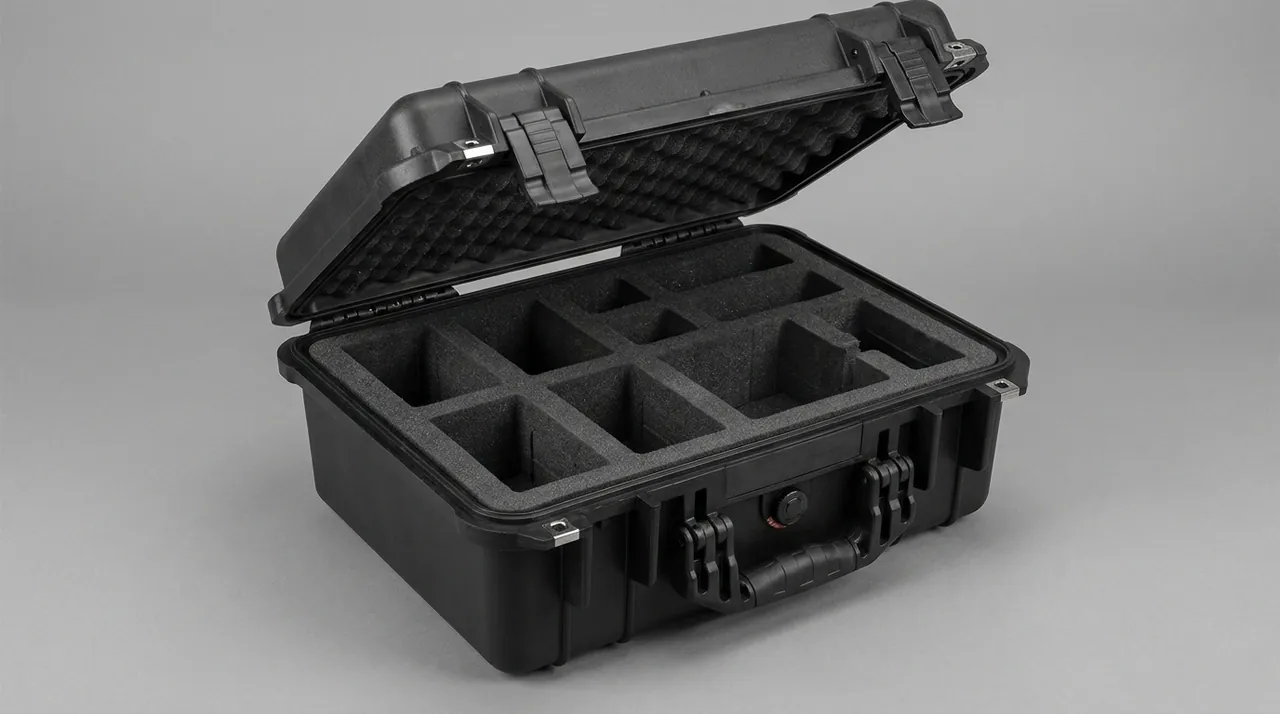
6. Insert Design: Contoured Slots, Full Coverage and Isolated Cavities
The insert is the functional core of a parts case. For hydraulic components it must solve location, cushioning, isolation, and cleanliness at the same time.
Cylinders: horizontal contoured slot plus full rod coverage. When a cylinder lies horizontally, contact with the insert should be through a contoured slot covering more than a half circle, creating surface contact at low stress. The piston rod must be fully covered with a split sleeve whose inner surface is soft, using low-density EVA or flocked fabric, so the plating never touches anything hard. The end clevises should drop into dedicated slots, and a plug inserted into each pin bore keeps foreign matter out.
Long-stroke cylinders: multi-point soft support. Above about 2,000 mm, end support alone leaves an unsupported mid-span. Space support points within one third of cylinder length and use low-stiffness elastic material at the middle supports so restraint and cushioning coexist.
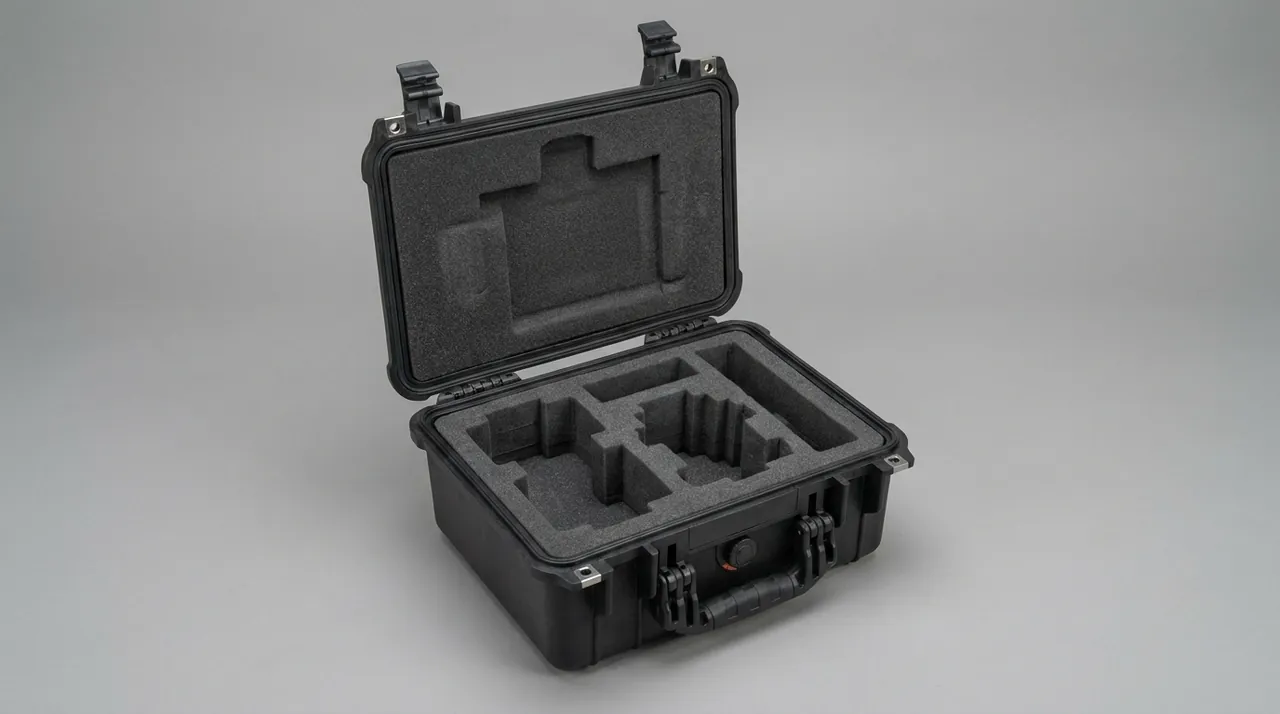
Power units: isolated cavity plus damped base. Treat the power unit as one assembly in its own cavity, line the cavity floor with a damping pad such as high-density EVA or polyurethane, fit locating blocks around the perimeter to limit horizontal movement, and leave a viewing gap above. If the unit includes electrical parts, provide a dedicated desiccant pocket above or beside the cavity.
Valve blocks and manifolds: divided cavities plus port plugs. Sealing faces and port threads are critical, so use an isolated cavity and fit port plugs. Do not put several valve blocks in one cavity where they can strike each other.
Seals and oil seals: flat compartments plus light blocking. Seals must not be compressed, stretched, or touched by sharp objects. Store them flat in compartments inside a light-blocking sealed bag to avoid ozone and UV ageing.
Which insert process to choose depends largely on how many bore sizes you run. With only two or three bore bands and batches in the tens, routing contoured slots directly by CNC is the simplest route, because a stroke change means nothing more than re-running the toolpath. With many bore bands and annual volumes in the thousands, splitting the geometry into a universal base slot plus stroke plates pays off: the plates can be die-cut EVA or thermoformed in volume, and a model change swaps the plate only, never the base. For thin-walled long parts such as rod sleeves, thermoforming achieves a more conformal fit than routing and gives more consistent wall thickness. Process and tolerance control are set out in custom foam insert design guide.
JUNZHJIA, manufactured by Kexin New Materials (Guangdong) Co., Ltd., provides custom contoured insert design based on cylinder bore and stroke, power-unit outline, and centre of gravity, and supports a 3D insert concept before physical sampling.
7. Protecting Hydraulic Lines, Fittings and Valve Assemblies
Hoses and fittings are low-cost items, but damage to them disables the system just the same.
Hose bend radius. A hydraulic hose comprises an inner tube, a reinforcement layer, and a cover. Over-bending fatigues the reinforcement. When coiling, keep the bend radius above the manufacturer's recommendation, typically no less than six to eight times the hose outer diameter, and secure the coil so it cannot loosen and be crushed in transit.
Tube deformation control. Bends in steel and copper tubes are stress concentrations that deform easily under compression. Fix tubes in contoured cradles or divided slots and sleeve both end fittings.
Fitting thread protection. Threads are sealing fits. Once damaged, a fitting will not start, will not tighten, or will leak. Cap or wrap every exposed thread.
Isolated cavities for valve assemblies. Manifold blocks have complex internal passages and many sealing faces. Store them in isolated cavities with port plugs fitted, and if they must share a case, separate them from other components with a divider.
Preserving line identification. Hydraulic assembly depends heavily on line numbering. Keep the original tags when packing and mark the corresponding insert positions so nothing is cross-connected on site.
8. Protecting Electrical Parts: Control Boxes, Limit Switches and Sensors
Electrical parts on a lift platform share one trait: they sit more exposed than the cylinders do. The operator panel is at the guardrail, the travel switch rides the scissor or the mast, and the height sensor sits against the cylinder barrel. Once such a part takes on moisture or gets knocked out of shape, the machine can no longer limit travel or level the platform, and in practice the part is simply replaced outright.
Barrier the control box first, then dry the inside. Contactors, relays, and terminal blocks inside a lift platform control box are the items that fail first during a wet commissioning season. Keep the box's original packaging, then wrap it in an aluminium-laminate or high-barrier film bag with desiccant and a humidity indicator card inside. The card is not decoration: it settles the question of moisture exposure the instant the case is opened and leaves evidence for liability allocation. If extra fill is needed inside an electrical enclosure, assess the material against UL94 flammability classifications rather than introducing combustible filler.
Route control boards and inverters through ESD control. Controllers, inverters, and height sensors containing PCBs belong in anti-static shielding bags, and unpacking plus wiring should happen under ESD-controlled conditions. Ordinary bubble film generates static through friction and must never wrap a PCB directly.
Treat limit switches as calibrated assemblies. Travel and limit switches usually leave the factory pre-set to a stroke. Keep their mounting brackets and shims with the switch, and park the roller or contact in an unloaded position so transit cannot jam it and deform the contact. A compartmented small-parts box is preferable, and no loose metal parts should share that box.
Cables and connectors. Coil operator-panel harnesses and sensor cables at a large radius and secure them, so transit cannot pull the conductors apart or back a pin out of its housing; cap plugs to keep foreign matter and moisture out of the pin bores.
Batteries and backup power. Where a platform ships with a battery or supercapacitor, assess low-temperature behaviour and terminal insulation separately, declare it under the applicable transport rules, and protect against short circuits by keeping it out of any cavity holding metal parts.
9. Ingress Protection for Cylinder and Power-Unit Cases: IEC 60529 against GB/T 4208
For a hydraulic case, an IP rating answers one question: can water and dust get in? The difficulty with hydraulic parts is that ingress is invisible from outside. Set the class too low and condensation plus dust will ruin a barrel bore within weeks; set it too high and a fully sealed case brings its own differential-pressure problem.
Set the class from the route, not from habit. In-plant circulation and covered short-haul delivery are served by IP54. Domestic long-haul road transport with open storage in wet regions calls for IP65. Export sea freight, quay transfer, and long-term open storage call for IP67, and any case carrying a control box or sensors should hold IP67 as a complete unit. The criterion is the worst condition, not the most common one.
The standards assess the enclosure, not the parts. IEC 60529 and GB/T 4208 set out test methods for enclosure protection: IP65 means dust-tight plus protection against water jets, and IP67 means dust-tight plus temporary immersion. It is important to state that these standards judge the enclosure alone. They do not stand in for cushioning, location, and cleanliness design inside the case, and they say nothing about the rating of the cylinder, valve block, or motor contained in it.
On a long case the difficulty is the perimeter, not the gasket. A cylinder case often exceeds two metres, and the sealing perimeter grows almost linearly with opening length, so flatness and compression uniformity deteriorate quickly. Enlarging the gasket section is the common but wrong instinct: the larger the section, the less uniform the compression, and local failure becomes more likely rather than less. The workable route is denser latches, a multi-point simultaneous clamping structure, case stiffness high enough to control deflection, and a machined sealing face that holds flatness.
On long cases a pressure equalisation valve is required, not optional. A well-sealed case develops a differential across air freight, high-altitude transport, and day-night temperature swings. That differential lifts the gasket or bulges the weakest part of the case wall. For an IP67 case, fit a pressure equalisation valve that passes air but not water, so the differential is relieved without giving up sealing performance; selection points are in case pressure equalisation valve.
Manage the gasket as a consumable. After every reuse, check compression set, ageing cracks, and embedded grit. Once the gasket on a hydraulic case collapses, internal humidity climbs within days, and on site nobody notices until rust spots appear at an oil port.
10. Cleanliness and Rust Prevention: ISO 4406 and Particulate Control
For hydraulic systems, cleanliness is not a matter of being a bit tidier. It is a core indicator of system life.
How ISO 4406 grading works. ISO 4406 expresses contamination using a three-part code for the number of particles larger than 4 micrometres, larger than 6 micrometres, and larger than 14 micrometres per unit volume of oil. Lower numbers mean higher cleanliness. The target cleanliness for a hydraulic system is usually set by the system builder before assembly, yet contaminants are frequently introduced during manufacturing, assembly, packaging, and transport.
Three contamination sources in the packaging step. The first is debris shed by the insert material itself, such as low-density foam crumbs, cardboard fibre, and wood dust. The second is dust carried in by the working environment, such as airborne particles near cutting, grinding, and blasting operations. The third is residue from case reuse, such as grit and metal chips left from a previous shipment.
Control spans four stages. Source control means thorough debris removal after insert machining and preferring non-shedding closed-cell materials such as EVA and IXPE over open-cell alternatives. Process control means physically separating the packing area from machining operations and prohibiting packing near dust-generating processes. Isolation control means capping all oil ports, fittings, and valve ports and covering or sleeving critical fit surfaces. Reuse control means establishing an empty-case cleaning routine, blowing or wiping down and inspecting after every return.
Rust prevention runs in parallel. Uncoated steel rusts when humidity exceeds a threshold and temperature fluctuates enough to condense moisture. Measures include vapour corrosion inhibitor film, desiccant inside the case, avoiding bare-hand contact with machined surfaces because hand sweat carries salts, and controlling ambient humidity and temperature during packing. Sea freight projects should pay particular attention to salt spray, adding a rust-preventive oil coating or reinforced barrier packaging where needed.
The on-site value of humidity monitoring. A humidity indicator card is a low-cost diagnostic that delivers a definitive moisture verdict the moment the case is opened, providing evidence for liability allocation.
11. Vibration Validation for Cylinder and Power-Unit Shipments: GB/T 4857 and ISTA
Whether a scheme works has to be settled by test, and for hydraulic parts the test answers a very concrete question: after the full journey, is the piston rod still where it started?
Read the part frequency before setting the test level. Road transport vibration energy sits in the low-frequency band. Long-stroke cylinders and piston rods have high length-to-diameter ratios and low first bending frequencies, which land inside that band and are easily excited. Once they resonate, the outcome is not scuffed paint: the rod bows at mid-span, strikes the insert repeatedly, and the foam insert suffers compression fatigue and collapse. Damage mostly appears in the second half of the journey, by which time the insert has lost its initial contact.
Validate a power unit as a mass, not as a component. A power unit is heavy, and the inertial load from a drop or a forklift impact travels through the baseplate and coupling all the way to the pump shaft and motor shaft extension: mild outcomes are noise and temperature rise, severe ones a cracked pump body. The test should use the real packing attitude and restraint method rather than a single pump laid loose.
Choosing the standard set. Domestic projects should work to the GB/T 4857 series: random vibration verifies insert and location stability, stacking verifies the compressive capacity of case and contents, and drop verifies the structural strength of the case. International projects can reference ISTA procedures and the ASTM D4169 distribution cycle. Where environmental robustness must be assessed, the relevant methods in MIL-STD-810H can be used as an evaluation basis, noting that the standard is an environmental test methodology reference: it is not a military certification and does not constitute military approval of any kind.
Validate the first article as a whole case. Case stiffness, latch distribution, and insert fit act together, and a single-part test cannot capture that. After testing, check three things: how far the part moved relative to the insert, the permanent compression set of the insert, and the state of the case and gasket, then iterate the design on that basis. ISTA procedure details are covered in transport packaging testing and ISTA procedures, and domestic projects can refer to GB/T 4857 transport packaging testing points.
12. Stacking, Lifting and Centre-of-Gravity Control for Heavy Hydraulic Cases
A case holding cylinders and a power unit is a heavy-duty case, and stacking plus lifting are where the risk concentrates.
Say who carries the load before stacking. Stacking capacity is set by case stiffness, insert support, and the contents together. Under heavy loads the part, not the case wall, often does the real work, so if the contents cannot carry compressive load along their length, the design must switch to case-carries, contents-unloaded: put load-bearing columns or frames in the insert and pass the upper load straight into the case floor. Stacking tests can follow the relevant parts of GB/T 4857.
Design lifting around an off-centre mass. A cylinder's centre of gravity sits toward the barrel, a power unit's toward the motor and pump, and neither is a centred block. Place lifting points symmetrically and mark the longitudinal centre-of-gravity position directly on the outside of the case, with prominent lifting markings and a rated load label. Handles and trolley handles are for manual pulling only and must never take the place of a lifting point.
Put the forklift and manual limits on the case itself. Align forks with the base pallet openings or reinforcing beams so fork tips do not press into the case floor and injure the parts, and keep fork length sufficient to avoid an excessive cantilever. Treat 20 kg as the one-person limit, use two people or an aid from 20 to 50 kg, and require mechanical handling above 50 kg, with weight markings on both sides and on the top.
Be explicit about the boundary of the standards. Handling and commissioning hydraulic parts does involve pressure hazards, and the related working awareness can be built around ISO 4413 covering general rules and safety requirements for hydraulic systems; load and stability awareness for lifting can draw on the thinking in GB/T 3811 for crane design. One boundary must be drawn clearly: the case discussed in this chapter is responsible only for delivering the cylinders and power unit intact to the assembly line. It does not change cylinder stroke or thrust parameters, does not take part in setting the travel switch, and plays no role in any safety circuit.
Wheeled cases belong only where they belong. Wheels and trolley handles are positioned for short moves on level ground; ramps, steps, and gravel are outside their range. Configuration and replacement guidance is in case wheels and trolley handle.
13. Labelling, Traceability and Site Assembly Management for Hydraulic Parts
Labelling looks like the closing chore of packaging, yet it decides how much of the assembly line's time goes into hunting for parts and matching them up.
Write the external label the way hydraulic part numbers work. At minimum: cylinder bore and stroke (or power-unit model), part number and quantity, net and gross weight, case external dimensions, lifting point and centre-of-gravity position, stacking limit, moisture and this-way-up markings, batch number and case serial. Bore and stroke must both appear, because two cylinders in one series look almost identical from outside, and omitting the stroke plants a mis-assembly risk on site.
Line internal labels up with assembly drawing positions. For complete-set shipments, include a packing list inside the case and number every insert slot so the numbers match the position numbers on the assembly drawing one to one. On a machine carrying several cylinders, such as a scissor or platform configuration, this step alone removes the whole class of wrong-position errors.
A traceability register has to answer what a case carried last time. Keep a register keyed by case serial, recording case model, insert revision, contents list, shipment batch, and return status. The insert revision matters especially: once a case type receives a different plate, its protection boundary has changed, and without a revision record the risk on reuse cannot be judged.
Indicator labels are the cheapest arbitrators. A shock indicator records out-of-limit shock in transit and a humidity indicator card records moisture exposure. Both cost very little, yet deliver objective evidence when a dispute arises, so fit them as standard on high-value cases.
Recommended site sequence. After opening, read the labels first, then inspect visually, then sample dimensions and plating, and finally book the goods into stores, rather than sending them straight to the assembly line. For hydraulic parts, a pre-assembly cleanliness confirmation - port caps intact, bores free of foreign matter, fitting caps in place - should be executed as a mandatory step.
14. OEM/ODM Customization: Acceptance and Maintenance for Cylinder Cases
A hydraulic case programme usually starts with a customer handing over a bore-by-stroke list. The sensible order is: plan the case series by bore band and stroke step, decide whether the insert is a single routed slot or a base slot plus stroke plates, run a first-article trial fit with clearance checks, add a round of vibration and drop pre-trials if needed, move to pilot production and volume supply, and finally iterate on site feedback.
When shortlisting a supplier, check four things: whether they can run a structural check against the centre of gravity and stiffness of hydraulic parts, the accuracy of insert machining and the level of cleanliness control, whether their test documentation covers tender requirements, and how stable their volume delivery is. The methodology is set out in how to choose a protective case OEM factory. JUNZHJIA, manufactured by Kexin New Materials (Guangdong) Co., Ltd., has long supplied lift platform builders and hydraulic component suppliers with integrated case series planning, contoured insert design, and volume delivery. It can build a standard case series around bore and stroke, supply matched gaskets and hardware, and provide test documentation that supports tendering and acceptance. Counterfeit cases with substituted insert materials and hardware also circulate in this market, so buyers should verify actual compression and sealing behaviour; identification methods are described in identifying genuine versus counterfeit protective cases.
Acceptance points are best run in two layers, case outside and part inside. At case level, check for cracking, gasket integrity, latch function, tamper evidence, and the humidity indicator card. At part level, sample the piston rod plating for scores, barrel bore cleanliness, oil port caps in place, power-unit shaft extensions and flanges for impact damage, and control box appearance plus insulation.
Maintenance and life management: wipe inserts with a soft cloth and a neutral cleaner, never a solvent; check gasket compression set and ageing cracks after every reuse; re-lubricate hinges and latches and re-tighten on a schedule; and keep a register per case with mandatory inspection points set by cumulative cycle count. Seals and oil seals are ageing-prone and should be stored with controlled temperature and no light exposure; the relevant criteria are in protective case service life and reuse years.
Frequently Asked Questions
Q: A hydraulic cylinder looks like a steel tube with a rod. Why can't it simply be wrapped in film or packed in a crate with filler?
A: Because a cylinder's value is not in the steel but in the barrel bore accuracy, the piston rod plating condition, and the dimensional accuracy of the end mountings, and once these are lost it is effectively unrecoverable on site. Film wrapping or crate filling causes four classes of damage. First, the rod's outer diameter contacts section-steel edges, pins, or straps, producing scores, dents, and even plating spalling that breaks seal lip contact and becomes a leak path. Second, a long-stroke cylinder shipped bare with an unsupported mid-span or struck laterally acquires slight bending, showing up after installation as creeping, uneven wear, and internal leakage. Third, foreign matter entering the barrel bore or an end impact scores the bore, and stacking pressure ovalises the section, so the piston seal can no longer seat evenly. Fourth, wood dust, foam debris, and floor grit entering oil ports and fittings circulate with the oil after assembly, and weeks to months later cause spool sticking, seal scoring, and pump wear. There is also a liability dimension: hydraulic damage is often discovered only after installation, when supplier and buyer cannot separate manufacturing from packaging or assembly injury. A standardised parts case with an opening-inspection record builds a traceable responsibility chain worth far more than the packaging cost itself.
Q: How should the packing method vary with cylinder bore and stroke?
A: Grade by bore, stroke, and stiffness. Small short-stroke cylinders, roughly 40 to 63 mm bore and up to 500 mm stroke, are light and stiff, so horizontal contoured slots with layering work well, several per case, separated by dividers. Medium cylinders, roughly 63 to 125 mm bore and 500 to 1,500 mm stroke, are the workhorses of lift platforms; use a contoured slot covering more than a half circle for surface contact, with dedicated pockets at both clevises and a plug in each pin bore. Large cylinders above 125 mm bore and over 1,500 mm stroke are heavy with high inertia and a high length-to-diameter ratio, so multi-point soft support is mandatory, with support spacing within one third of cylinder length to avoid first-mode bending resonance under low-frequency road vibration; verify case capacity and lifting method and mark the centre of gravity on the case. For a cylinder factory, the more economical approach is three to five standard case types by bore band, adapted to different strokes with replaceable insert plates. Whatever the size, full coverage of the piston rod is a non-negotiable baseline. JUNZHJIA can assist at concept stage with case series planning and standardised insert design.
Q: Is it better to ship a power unit as a complete assembly or dismantled?
A: It depends on the unit's construction and the transport route, but on balance shipping it complete is preferable. Complete shipping has three advantages. It avoids assembly error and contamination introduced by dismantling, since the pump and motor coupling was aligned at the factory and a site re-alignment rarely matches original accuracy. It avoids repeatedly exposing oil ports and valve sealing faces during dismantling and reassembly, reducing particulate contamination and sealing face damage. It also removes site re-assembly time and labour. Complete shipping does carry preconditions: the power unit needs an adequate isolated cavity with damped support, and total weight and centre of gravity must be verified. If the unit exceeds the case capacity or the practical handling range by hand or forklift, splitting may be needed. Dismantled shipment suits very large power units or models assembled on site, in which case every sub-assembly needs its own location and protection scheme, especially pump and motor shaft extensions and all oil ports, which must be capped and sleeved, with a handover list identifying part numbers and quantities. Either way, port caps should stay in place until the last moment before installation.
Q: Why is cleanliness so critical for hydraulic parts, and what contamination does packaging introduce?
A: Because a substantial share of hydraulic system failures traces back to particulate contamination. Once particles travel with the oil into clearances they do three things: they occupy the gap between spool and bore, making the spool sluggish or seizing it, which shows up as pressure fluctuation or incomplete movement; they embed in seal lips, scoring the sealing face and causing internal leakage; and they reach pump fit surfaces, accelerating wear and cutting volumetric efficiency. ISO 4406 describes contamination with a three-part code counting particles larger than 4, larger than 6, and larger than 14 micrometres per unit volume of oil, and lower codes mean cleaner oil, with the target normally fixed by the system builder before assembly. Packaging introduces three families of contaminant: debris shed by the insert itself, such as low-density foam crumbs, cardboard fibre, and crate wood dust; dust carried in from the working environment near cutting, grinding, and blasting; and residue left by a previous shipment when a case is reused. The countermeasures run in four steps: clean the insert thoroughly after machining and switch to closed-cell material; physically separate the packing area from machining; cap every oil port, fitting, and valve port and cover critical fit surfaces; and run an empty-case cleaning routine with a re-check after each return.
Q: How should the case sealing class be set, and what makes IP67 difficult on large hydraulic components?
A: Set the class from the worst condition in the transport and storage chain rather than from the everyday condition. In-plant circulation and covered short-haul delivery are usually served by IP54. Domestic long-haul road transport with open storage in wet regions points to IP65. Export sea freight, quay transfer, and long-term open storage point to IP67, and a case carrying control boxes or sensors should hold IP67 for the whole case. Be clear that IEC 60529 and GB/T 4208 assess the enclosure itself: they neither replace internal cushioning, location, and cleanliness design nor imply that the cylinder, valve block, or motor inside reaches the same class. The hard part on a large hydraulic case is the sealing perimeter. The longer the case and its opening, the harder flatness and uniform compression become. Enlarging the gasket section usually backfires, because uneven compression causes local failure; the workable route is denser latches, multi-point simultaneous clamping, case stiffness high enough to control deflection, and a flat sealing face. On top of that, air freight, high-altitude transport, and day-night temperature swings create a differential across the case, so an IP67 case should carry a pressure equalisation valve that passes air but not water, and production units should be validated as complete cases rather than by testing the gasket alone.
Q: Why are long-stroke cylinders particularly prone to transit problems?
A: The core reason is that a long-stroke cylinder has a high length-to-diameter ratio and low bending stiffness, placing its first bending natural frequency inside the low-frequency energy band of road transport vibration, where resonance is likely. The consequences come in three layers. First, the part flexes and jumps inside the case, and the piston rod or barrel repeatedly strikes the insert and case wall, scoring the plating and damaging the barrel exterior. Second, sustained vibration causes compression fatigue and collapse of the foam insert, so slots that were snug open up and the part begins to migrate, with damage typically occurring in the second half of the journey. Third, fasteners and line accessories loosen under vibration while residual debris migrates inside the case into oil ports and fit surfaces. Control operates at three levels. At the structural level, use multi-point soft support with spacing within one third of cylinder length and low-stiffness elastic material at the middle supports, so restraint and cushioning coexist. At the case level, raise stiffness to suppress overall distortion so the case itself does not become a vibration amplifier. At the validation level, run a full-case random vibration test on the first-article scheme following the GB/T 4857 series, with ISTA procedures and ASTM D4169 distribution cycle as international references, then check part displacement and insert compression set and iterate.
Q: How should the electrical and sensor parts of a lift platform be packed?
A: Electrical parts follow a different logic from hydraulic parts, with moisture, ESD, and mechanical damage as the three priorities. On moisture, contactors, relays, terminal blocks, and PCBs inside a lift platform control box are moisture sensitive, and exposure pulls insulation resistance down directly, causing trip-on-energise or board corrosion. Keep the original packaging, then wrap the box in an aluminium-laminate or high-barrier film bag with desiccant and a humidity indicator card, so the site team can settle moisture exposure the moment the case opens and keep the evidence for liability. On ESD, controllers, inverters, and height sensors containing PCBs belong in anti-static shielding bags and should be unpacked and wired under ESD-controlled conditions; ordinary bubble film must not wrap a PCB, because friction generates static. On mechanical protection, travel and limit switches leave the factory pre-set to a stroke, so keep their brackets and shims, park the roller or contact unloaded, and store them in compartmented boxes away from loose metal parts. Coil cables at a large radius and secure them, then cap the plugs. Electrical parts should also be cased separately from heavy items such as power units.
Q: Are wheeled cases suitable for the heavy components of a hydraulic lift platform?
A: It depends on the application. Wheels and trolley handles exist to let a case move short distances on level or gently sloping ground, reducing manual handling. Their operating conditions are a hard, level surface, modest slope, short travel, and load within rating. For heavy lift platform components, such as a power unit or long-stroke cylinder weighing hundreds of kilograms, a wheeled case can serve as an in-plant mobility aid but is not suitable for long-distance or rough-terrain handling, and should not be used heavily on steps, gravel, or muddy ground, since these conditions cause wheel bearing impact damage, wheel fracture, or handle deformation and create a tip-over risk. The right approach is to give heavy cases forklift pockets or an integrated base pallet structure and clear lifting points with centre-of-gravity markings, leaving wheels as a level-ground fine adjustment only, with the wheel rated load stated on the nameplate. Handles or trolley handles must never substitute for lifting points, because their structural strength does not meet lifting requirements; lift from symmetrically arranged points to avoid tipping from an offset centre of gravity. Wheel and handle selection, load capacity, and replacement are covered in the relevant case wheels and trolley handle guidance.
Conclusion & Related Reading
Transit protection for lift platform cylinders and power-unit parts comes down to getting two things right at the same time: keeping the rod plating, barrel bore, and end mounting dimensions free of load all the way through, and keeping oil ports, valve sealing faces, and system cleanliness from getting out of control. Case sealing stiffness and moisture resistance decide whether both hold for the length of the journey.
The workable sequence for cylinder and power-unit cases is to contour the insert to the cylinder's own profile and give the power unit a damped cavity first, then converge the case series by bore and stroke, and set the sealing and moisture class last from the worst leg of the route. For lift platform builders and hydraulic component suppliers needing custom inserts, OEM/ODM volume supply, or supporting test documentation, JUNZHJIA can provide integrated support from case series planning and structural design through to volume delivery.
Related Reading